

MLT 3 Addendum for Suppressed Ranges in Gas Purity Applications-4th Ed.
Table of contents
 Loading...
Rosemount MLT 3 Addendum for Suppressed Ranges in Gas Purity Applications-4th Ed. Manuals & Guides

Instruction Manual
90002929_ML T 3
12/2007
Addendum
MLT 3 (Suppressed Ranges - Gas Purity)
for Instruction Manual
NGA 2000 Hardware Manual for MLT
th
4
Edition 12/2007
www.EmersonProcess.com

Instruction Manual
90002929_ML T 3
12/2007
Emerson Process Management (Rosemount Analytical) designs, manufactures and tests
its products to meet many national and international standards. Because these
instruments are sophisticated technical products, you MUST properly install, use, and
maintain them to ensure they continue to operate within their normal specifications. The
following instructions MUST be adhered to and integrated into your safety program when
installing, using and maintaining Emerson Process Management (Rosemount Analytical)
products. Failure to follow the proper instructions may cause any one of the following
situations to occur: Loss of life; personal injury; property damage; damage to this
instrument; and warranty invalidation.
• Read all instructions prior to installing, operating, and servicing the product.
• If you do not understand any of the instructions, contact your Emerson Process
Management (Rosemount Analytical) representative for clarification.
• Follow all warnings, cautions, and instructions marked on and supplied with the
product.
Addendum ML T 3 Gas Purity
ESSENTIAL INSTRUCTIONS
READ THIS PAGE BEFORE PROCEEDING!
• Inform and educate your personnel in the proper installation, operation, and
maintenance of the product.
• Install your equipment as specified in the Installation Instructions of the
appropriate Instruction Manual and per applicable local and national codes.
Connect all products to the proper electrical and pressure sources.
• To ensure proper performance, use qualified personnel to install, operate, update,
program, and maintain the product.
• When replacement parts are required, ensure that qualified people use replacement
parts specified by Emerson Process Management (Rosemount Analytical).
Unauthorized parts and procedures can affect the product’s performance, place the
safe operation of your process at risk, and VOID YOUR W ARRANTY. Look-alike
substitutions may result in fire, electrical hazards, or improper operation.
• Ensure that all equipment doors are closed and protective covers are in place,
except when maintenance is being performed by qualified persons, to prevent
electrical shock and personal injury.
The information contained in this document is subject to change without notice.
1st Edition 05/2004 2
nd
Edition 1 1/2004 3
rd
Edition 08/2007
4th Edition 12/2007
Emerson Process Management
GmbH & Co. OHG
Industriestrasse 1
D-63594 Hasselroth
Germany
T +49 (0) 6055 884-0
F +49 (0) 6055 884-209
Website: www.EmersonProcess.com

Instruction Manual
90002929_ML T 3
08/2007
Addendum ML T 3 Gas Purity
T able of Contents
1. Technical Description 1 - 1
1.1 Front View 1 - 1
1.2 Rear View 1 - 2
1.3 Internal Construction 1 - 3
1.3.1 Internal Gas Paths 1 - 4
2. Start-up 2 - 1
2.1 Installation Site 2 - 1
2.2 Gas Conditioning (Sample Handling) 2 - 1
2.2.1 Fine Dust Filter 2 - 2
2.2.2 Pressure Sensor 2 - 2
2.2.3 Gas Flow 2 - 2
2.3 Gas Connections 2 - 2
2.3.1 MLT 3 with solenoid valve block 2 - 3
3. Switching On 3 - 1
4. Calibration Procedure 4 - 1
4.1 Measurement 4 - 1
4.2 Calibration 4 - 1
4.2.1 Test Gases 4 - 2
4.2.2 Purge Time 4 - 2
5. Maintenance 5 - 1
6. Technical Data 6 - 1
www.EmersonProcess.com
I

Addendum ML T 3 Gas Purity Instruction Manual
90002929_ML T 3
08/2007
II
www.EmersonProcess.com

Instruction Manual
90002929_ML T 3
12/2007
Addendum ML T 3 Gas Purity
1. Technical Description
The ML T 3 analyzer for suppressed ranges in the gas purity application is part of the NGA 2000
MLT family . The MLT 3 is enclosed in a 19 " housing with thermostat control (55 °C). The physical
part (photometer bench, sensors etc.) is separated from the electronic part
(see also Fig.1-3)
The ML T 3 gas analyzer for N2O, CO2 or PO2 gas purity can measure in two measuring modes:
1. absolute range: 0 - 100 % CO2/ N2O / PO2 (paramagnetic oxygen)
2. suppressed range: 95 or 98 - 100 % CO2 / N2O / PO
Suppressed ranges, like 95 or 98-100 % CO2, N2O or PO2 , are strongly influenced by pressure,
temperature, flow and ambient CO2 and water vapor. Special means are necessary to keep these
factors as constant as possible to reduce their influence on the measurement.
An internal pressure regulator, capillary , pressure, temperature and flow sensor are provided to
control flow and allow compensation for temperature and barometric pressure variations.
A special calibration procedure is necessary to achieve the requested suppressed range (see
chapter 4). Purge of the optical bench with constant CO2 and H2O is requested (0.1-0.2 l/min).
The installation of the complete analytical equipment (MLT 3 gas analyzer, sample handling
system and calibration gases [zero and span gas] ) should be in an air conditioned room or at least
in a well ventilated room to fulfill the permissible ambient temperatures (20 to 30 °C).
2
1.1 Front View
The front panel of the analyzer is the operating front panel (see Fig. 1-1).
Measured values and the entire operating procedure are displayed on a LC display. The
operation and programming of the instrument is performed by using the four cursor keys, the
ENTER key and the five soft keys (see separate ML T Software Manual).
The MLT 3 front panel for gas purity measurements is identical with the standard MLT 3 front panel.
The internal mounting is described later under "Internal Construction" (see Fig. 1-3, 1-4).
F 3F 1 F 2 F 4 F 5
NGA 2000
www.EmersonProcess.com
Fig. 1-1: MLT 3 (1/1 19" housing), front view
1 - 1

Addendum ML T 3 Gas Purity
1.2 Rear View
Network connection (RJ 45 socket)
Instruction Manual
90002929_ML T 3
12/2007
IN
Ch 1
OUT
IN
Ch 2
OUT
optional PCB [SIO/DIO e.g.]
Input 230/120 V ac (UPS 01 T)
Gas connections
Fig. 1-2a: MLT 3 (standard version), Rear view
See Figures 1-2a and 1-2b for differences between the "standard ML T 3" and the "MLT 3 for
gas purity measurement". The "ML T 3 for gas purity measurement" is equipped with a
solenoid valve block for the supply of sample, zero and span gas, which is controlled by the
analyzer. The control is done with the relay outputs of I/O Board "SIO" via an external
connection cable "SIO => Solenoid V alve Block" (pin assignments see Fig. 21-4 in the
standard ML T manual).The gas connections are shown in Fig. 1-2b and are marked specific
to the application. The outlet of the valve block is connected to the gas inlet of the ML T 3.
Sub.-min. D, 9 pole
(to Solenoid Valve Block)
NETWORK
DIGITAL I/O
Sub.-min. D, 9 pole
(connection to PCB “SIO”)
!
Inlet Pressure:
min. 20 psig
max. 25 psig
Span gas
Out (Outlet)
230/120 V
50/60 Hz
max. 240 VA
Sample gas
Purge Gas Connections
(Purge Gas Inlet & Outlet)
Purge IN
IN (Inlet)
ANALOG I/O SERIAL I/O
Zero gas
OUT (Outlet)
Purge OUT
PCB "SIO" Sample Gas Connections
Input 230/120 V ac (PS UPS 01 T) Solenoid Valve Block
(Gas Inlet & Outlet)
Fig. 1-2b: MLT 3 (gas purity measurement), Rear view
1 - 2
www.EmersonProcess.com

Instruction Manual
90002929_ML T 3
12/2007
Addendum ML T 3 Gas Purity
1.3 Internal Construction
The photometer assembly and physical parts is located on the left side (front view) while the
electronic part with interconnection board and PCBs is located on the right.
Gas connections
(Gas inlet via valve
block, gas outlet,
Purge inlet/outlet, 1/4")
Pressure
Sensor
Flow
Sensor
Heating
Unit
Solenoid valve block
(zero, span & sample gas inlet, 1/8 ")
Power Supply
(UPS 01 T)
Card cage
(electronic
boards)
Pressure
regulator
www.EmersonProcess.com
Photometer bench
(MLT 3, suppressed range)
Fig. 1-3: MLT 3 (gas purity measurement), Top view
Fan
Operating Front Panel
(MLT 3 analyzer)
1 - 3

Addendum ML T 3 Gas Purity
Instruction Manual
90002929_ML T 3
12/2007
1.3.1 Internal Gas Paths
The materials used for the gas paths are selected to suit the intended application - gas purity
with suppressed N2O, CO2 or PO2 range. The gas inlet is connected by SS tubing to the
internal pressure regulator. This gas path also includes a fine dust safety filter (SS version).
A capillary is installed after the pressure regulator . This design enables a constant flow if the
requested inlet pressure is kept between 1.4 and 3 barg ( 20 to 45 psig. A pressure of 1.4 to
1.7 barg (20 to 25 psig) is recommended. The optional electronic flow sensor follows the
capillary . The outlet of the flow sensor is connected by a viton tubing to the photometer cell.
The measuring cell outlet is tubed in Viton to a Tee. One part of the Tee is connected to an
atmospheric pressure sensor. The other T ee part is tubed in V iton and connected to the gas
outlet fitting.
a) Gas Path Material
Fittings
The sample gas fittings located at the sample gas inlet (including the valve block), sample gas
outlet and between sample gas inlet, safety filter, pressure regulator and flow sensor are stainless
steel Swagelok® fittings.
The sample gas inlet fittings for zero, span and sample gas are 1/8" Swagelok® fittings. The
sample gas outlet is a 1/4" Swagelok® fitting.
The purge gas fittings for purge gas inlet and purge gas outlet are 1/4" PDF fittings,
Fig. 1-4 shows all fittings including the internal fittings.
Tubings
All gas path tubings from gas inlet at the solenoid valve block are SS. This includes all
connections from gas inlet to the flow sensor. The remaining gas paths are tubed in Viton
(from flow sensor to the outlet fitting).
1 - 4
www.EmersonProcess.com

Instruction Manual
Addendum ML T 3 Gas Purity
90002929_ML T 3
12/2007
b) Internal gas paths (Gas Path Lay-out)
The complete internal construction including all gas connections is shown in Fig. 1-4.
Up to the internal pressure regulator the gas paths are stainless steel tubings. The gas paths are
connected with viton tubing following the flow meter.
All external sample gas fittings are stainless steel Swagelok®, 1/8 " or 1/4 ". Purge gas fittings
are PVDF, 1/4 " or 6/4 mm.
Sample gas outlet
1/4”
Purge gas outlet
1/4”
Purge gas inlet
1/4”
rear side
Gas inlets valve block
1/8"
Span gas
Sample gas
Zero gas
1/8"
tube
6 mm
Analyzer gas inlet
6 mm
6 mm
tube piece
Viton tubing
safety dust filter
1/8"
SS Tubing
1/8"
Viton tubing
analysis cell
threated plug 1/8"
1/8"
pressure
sensor
Viton
Viton
1/16"
SS Capillary
front side
Flow
sensor
1/16"
www.EmersonProcess.com
Fig. 1-4: MLT 3 (gas purity measurement), gas path layout
(1 measuring channel with solenoid valve block option)
1 - 5

Addendum ML T 3 Gas Purity
Instruction Manual
90002929_ML T 3
12/2007
1 - 6
www.EmersonProcess.com

Instruction Manual
90002929_ML T 3
12/2007
Addendum ML T 3 Gas Purity
2. Start-up
Please check the packing and its contents immediately upon arrival.
If any item is damaged or lost you are kindly requested to notify the forwarder to undertake a
damage survey and report the loss or damage to us immediately .
2.1 Installation Site
Be sure to observe the additional notes, safety precautions and warnings
given in the individual manuals (see Analyzer Discription as well as
MLT Instruction Manual) !
The ML T must not operate in explosive atmosphere without supplementary
protective measures !
Free flow of air into and out of the ML T (ventilation slits) must not be hindered
by nearby objects or walls ! Purge gas is required for the optical bench:
approx. 0.1 to 0.2 l/min gas with constant CO2 (N2 or air via scrubber)!
The installation site for the ML T has to be dry and remain within the permissible
ambient temperature at all times. For suppressed ranges we recommend
installation between 20 °C and 30 °C ( 68 to 86 °F).
The ML T must be exposed neither to direct sunlight nor to strong sources of
heat. The room should be well ventilated or air conditioned.
Sample handling system and all calibration gases - zero gas and span gas should be installed under the same conditions (in one room).
2.2 Gas Conditioning (Sample Handling)
The conditioning of the sample gas is of greatest importance for the successful operation of any
analyzer.
All gases have to be supplied to the ML T as conditioned gases !
The use of corrosive gases is not provided for gas purity measurement with
suppressed ranges.
It is to be verified that there are no gas components which may damage
the gas path components.
www.EmersonProcess.com
2 - 1

Addendum ML T 3 Gas Purity
Instruction Manual
90002929_ML T 3
The gas has to fulfill the following conditions:
o It must be free of condensable constituents, free of dust and free of
aggressive constituents
o T emperatures and pressures within the specifications stated in “T echnical
Data” and under "Installation Site" of this manual.
For suppressed ranges a constant pressure between 1.4 and 3 barg (20 - 45 psig) and
controlled temperature (20 - 30 °C, 68 - 86 °F) are very important.
2.2.1 Fine Dust Filter
12/2007
The ML T 3 has a built-in fine dust safety filter (filter material SS).
2.2.2 Pressure Sensor
An atmospheric pressure sensor with a range of 950 - 1050 hPa is implemented to compensate
the analyzer concentration readings for changes of the barometric pressure (see T echnical Data).
2.2.3 Gas Flow
The gas flow rate is controlled by an internal pressure regulator (see Fig. 1-3 and 1-4) and the
correct gas inlet pressure of 1.4 to 3 barg (20 to 45 psig; recommended: 1.4 to 1.7 barg / 20 to
25 psig). There is an optional internal electronic flow sensor which allows monitoring the flow rate
on the analyzer display.
The range of the flow sensor is 0 - 2 l/min ( 0.2 l/min to 1.5 l/min max. recommended) !
2.3 Gas Connections
All fittings as well as gas inlet pressure are clearly marked.
The fittings are located on the rear panel of the ML T 3 instrument.
The exhaust gas lines have to be mounted in a declining slope.
The exhaust gas line at the gas outlet (OUT) should be a minimum 1/4'' od with
max. length less than 3 m (10 ft.), so that outlet pressure drops are insignificant.
2 - 2
www.EmersonProcess.com

Instruction Manual
90002929_ML T 3
12/2007
2.3.1 MLT 3 with solenoid valve block
The necessary gas connections are marked at the valve block.
Special requirements for inlet pressure are indicated as well:
A constant input pressure between 1.4 and 3 barg (20 to 45 psig) is necessary
for sample gas as well as for zero gas and span gas.
Addendum ML T 3 Gas Purity
The connections of sample gas, zero gas and span gas have to be fixed by the user to the solenoid
valve block on the rear side of the instrument (Fig. 1-2b and Fig. 2-1).
The common exhaust gas outlet (OUT) of the solenoid valve block is connected to the
"standard" sample gas inlet of the ML T 3 instrument via a stainless steel tubing (see Fig. 1-4).
Gas Inlets:
Span gas
OUT
Sample gas
Zero gas
(exhaust
gas outlet)
www.EmersonProcess.com
Fig. 2-1: Solenoid valve block MLT 3 (gas purity measurement) (side view)
2 - 3

Addendum ML T 3 Gas Purity
Instruction Manual
90002929_ML T 3
12/2007
2 - 4
www.EmersonProcess.com

Instruction Manual
90002929_ML T 3
12/2007
Addendum ML T 3 Gas Purity
3. Switching On
Be sure to observe the safety precautions and warnings !
Be sure to observe the additional notes, safety precautions and warnings
given in the individual manuals (see standard MLT Instruction Manual) !
Once the instrument has been correctly assembled and started up in accordance with the
general instructions given in section 2 "St art-up", the equipment is ready for operation.
The equipment is switched on by providing the required voltage.
Upon switching on, the analyzer will perform a self-diagnostic test routine.
For additional information about display messages during start-up see respective software
manual.
The "standard ML T 3" analyzer needs approx. 55 minutes to warm-up after
switching on, depending on the installed detectors and
thermostatically controlled temperature !
For suppressed ranges of 95/98 - 100 % CO2, N2O, PO
2
we recommend warming-up the analyzer over night and start calibration
next morning (12 hours ) to achieve best results!
www.EmersonProcess.com
3 - 1
Addendum ML T 3 Gas Purity
Instruction Manual
90002929_ML T 3
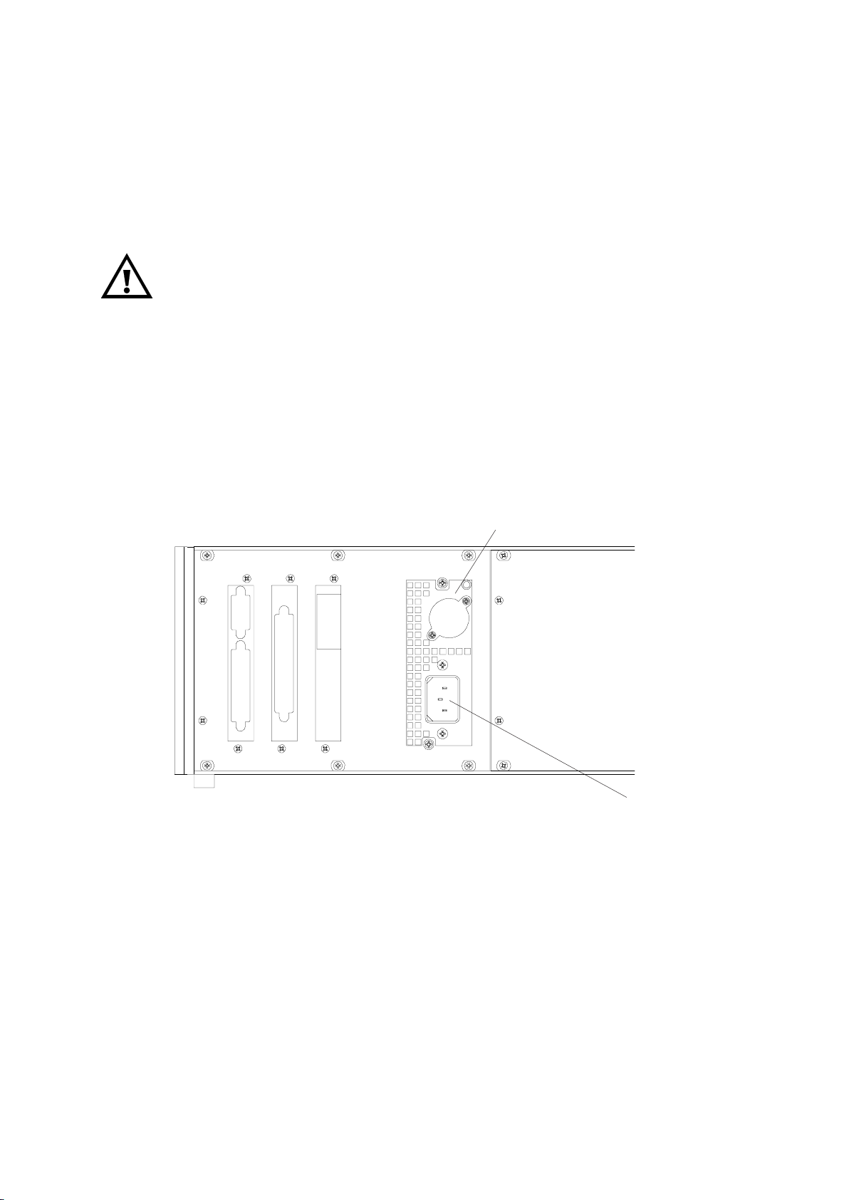
The equipment has an internal power supply with “autoranging” for operating voltages
of 230 V AC or 120 V AC resp., 47-63 Hz.
V erify beforehand that the line voltage stated on the power supply agrees
with that of your power supply line !
The socket outlet shall be installed near the equipment.
o Connect mains line and internal power supply (UPS 01 T)
(see Fig. 3-1, Plug AC).
12/2007
internal power supply
(UPS 01 T)
Fig. 3-1: MLT 3, Voltage supply
Input
230 / 120 V ac
3 - 2
www.EmersonProcess.com

Instruction Manual
90002929_ML T 3
08/2007
Addendum ML T 3 Gas Purity
4. Calibration Procedure
4.1 Measurement
Before starting gas purity measurement of a suppressed range the analyzer needs to be
warmed up adequately and the calibration procedure needs to be performed.
Then sample gas can be introduced into the analyzer .
Follow the start-up procedure before starting measurement!
4.2 Calibration
T o insure correct measurement results, zeroing and spanning should be carried out according
to the calibration procedure for suppressed ranges:
Calibration is carried out in the absolute range of:0 - 100 % CO2/N2O/PO
2
The zero adjustment must be done before running a span adjustment.
ML T 3 for gas purity measurement with suppressed range has to be calibrated once
a day!
For the calibration procedure the required zero and span gases have to be connected to the
analyzer through the respective gas inlets (valve block) with the same pressure as the sample gas !
For gas purity measurement an input pressure of 1.4 to 3 barg (20 - 45 psig) is
necessary for sample gas as well as for zero gas and span gases.
An inlet pressure of 1.4 to 1.7 barg (20-25 psig) is recommended!
o For correct adjustment of the analyzer please refer to the ML T software manual !
www.EmersonProcess.com
4 - 1

Addendum ML T 3 Gas Purity
4.2.1 Test Gases
a) Zero Gas
Instruction Manual
90002929_ML T 3
08/2007
For zeroing, the analyzer has to be flushed with 100 % nitrogen (N
) [best quality]
2
.
b) Span Gas
For spanning, the analyzer has to be adjusted with 100 % CO2/N2O/O2 [best quality].
Observe the safety regulations for the respective gases (sample gas, zero and
span gases) and the gas bottles!
Pressure of sample gas / test gases: 20 - 25 psig!
All calibration gases need to hold the same temperature as sample gas!
Sample gas need to be conditioned to the ambient temperature of the
analyzer (20 - 30 °C)!
4.2.2 Purge Time
Zero and span calibration requires a certain purge time. After that the calibration routine can take
place with the internal stability and averaging procedures (calibration time).
After switching back from the absolute measuring mode to the suppressed range the same purge
time is necessary again. The purge time is timed from the MLT 3 gas inlet (not including the
sample handling system):
purge time: > 240 sec (from sample to zero gas; from zero to span gas)
calibration time: approx. 40 sec
purge time: > 240 sec (from zero to span or sample gas; from span to zero gas)
4 - 2
www.EmersonProcess.com

Instruction Manual
90002929_ML T 3
08/2007
Addendum ML T 3 Gas Purity
5. Maintenance
In general only the sample handling system (gas conditioning) will require maintenance; the
analyzer itself requires very little maintenance.
The following checks are recommended for maintenance of the proper operation of the analyzer.
Zero adjustment: daily
Span adjustment: daily
Leak testing: 6 times annually.
The maintenance frequencies stated above are presented as guidelines only:
Maintenance operations may be required more or less frequently , depending upon usage and
site conditions.
For gas purity measurements with suppressed ranges a daily zeroing is strongly recommended.
Sp an gas adjustment may be necessary less frequently depending on recognized span gas
deviations. It might be extended from daily adjustment after practical experience.
www.EmersonProcess.com
5 - 1

Addendum ML T 3 Gas Purity
Instruction Manual
90002929_ML T 3
08/2007
5 - 2
www.EmersonProcess.com

Instruction Manual
Addendum ML T 3 Gas Purity
90002929_ML T 3
12-/2007
6. Technical Data
For "complete and standard Technical Data" refer to the standard MLT Instruction Manual.
SPECIFICATIONS - MLT 3: Gas Purity - Absolute and Suppressed Range
0 - 100 % CO
2
95/98 - 100 % CO
2
0 - 100 % N2O 95/98 - 100 % N2O
0 - 100 % PO
Detection limit < 1 %
Linearity < 1 %
Zero-point drift < 2 % per week 1)
Span (sensitivity) drift < 0.5 % per week 1)
Repeatability < 1 %
Response time (t90) 3 s < t90 < 30 s
1) 4)
1) 4)
1) 4)
3) 5)
2
Noise < 2 %
4)
4)
Linearity < 2 %
Zero-point drift < 800 / 500 ppm per day
Span (sensitivity) drift < 800 / 500 ppm per day
Resolution 800 / 500 ppm
Response time (t90) < 30 s
Permissible gas flow 0.2 - 1.5 l/min Gas flow (internal press. regulator) defined by inlet pressure
Influence of gas flow - Inlet pressure 1.4 to 3 barg (20 to 45 psig)
Max. pressure < 1,500 hPa abs. Min. Pressure 1.4 barg (20 psig )
Max. pressure 3 barg (45 psig); 1.7 barg (25
Influence of pressure psig)
- At constant temperature < 0.1 % per hPa
- With pressure compensation
10)
< 0.01 % per hPa
Permissible ambient temperature + 5 °C to + 40 °C
2)
2)
7)
Influence of atmospheric pressure < +-2 %
- 950 to 1050 hPa (at const. temp.)
with pressure compensation
Influence of temperature Influence of temperature + 20°C to + 30°C
(at constant pressure) (at constant pressure)
- On zero point
- On span (sensitivity) < 5 % (+ 5 to + 40°C)
Thermostat control
Warm-up time
12)
12)
< 1 % per 10 K
55 °C Thermostat control 55 °C
Approx. 50 minutes Warm-up time
1)
- On zero point < +-2 %
1) 6)
- On span (sensitivity) < +-2 %
12)
Purge gas for optical bench (CO
(N2 or air with const. CO2 & H2O)
95/98 - 100 % PO
8) 4)
8) 4)
3) 13)
15)
8) 14)
10)
8)
8)
Approx. 50 minutes
O) Approx. 0.1 - 0.2 l/min
2/N2
2
4) 9) 11) 16)
4) 9) 11) 16)
16)
14)
7)
9)
1) Related to full scale
2) Related to measuring value
3) From gas analyzer inlet at 0.8 l/min gas flow
4) Constant pressure and temperature
5) Depending on integrated photometer bench
6)
Starting from 20°C (to + 5°C or to + 40°C)
7) Different ambient temperatures (15 - 35 °C)
on request
www.EmersonProcess.com
8) Related to suppressed range (95/98 - 100 % CO2/N2O/
PO2)
9) Between min. and max. pressure
10)Barometric pressure sensor required
11) Daily calibration requested
12)Thermostatically controlled box: 55 °C, warm-up time
approx. 50 min. (ambient temperature: 20-30 °C);
Final stability: over night warm-up recommended!
13) Switch from absolute to suppressed range requires
purge time of > 240 seconds
14) Gas outlet open to atmosphere (tube 1/4", 3 m length)
15) Recommended inlet pressure
16) 800 ppm with 95...100 %; 500 ppm with 98...100%
6 - 1

Addendum MLT 3 Gas Purity
WORLD HEADQUARTERS
ROSEMOUNT ANAL YTICAL EUROPE
Emerson Process Management
GmbH & Co. OHG
Industriestrasse 1
63594 Hasselroth
Germany
T 49 6055 884 0
F 49 6055 884209
Emerson Process Management
Rosemount Analytical Inc.
6565 P Davis Industrial Parkway
Solon, OH 44139 USA
T 440.914.1261
Toll Free in US and Canada 800.433.6076
F 440.914.1271
e-mail: gas.csc@EmersonProcess.com
www.raihome.com
GAS CHROMAT OGRAPHY CENTER
AND LATIN AMERICA
Emerson Process Management
Rosemount Analytical Inc.
11100 Brittmoore Park Drive
Houston, TX 77041
T 713 467 6000
F 713 827 3329
Instruction Manual
90002929_ML T 3
12/2007
EUROPE, MIDDLE EAST AND AFRICA
Emerson Process Management
Shared Services Limited
Heath Place
Bognor Regis
West Sussex PO22 9SH
England
T 44 1243 863121
F 44 1243 845354
ASIA-PACIFIC
Emerson Process Management
Asia Pacific Private Limited
1 Pandan Crescent
Singapore 128461
Republic of Singapore
T 65 6 777 8211
F 65 6 777 0947
e-mail: analytical@ap.emersonprocess.com
© Emerson Process Management GmbH & Co. OHG 2007
Loading...