

Page 1
Net Safety™ Millennium
Air Particle Monitor (APM) Oil Mist Detector
Reference Manual
00809-0100-4077, Rev AB
May 2018
Page 2

Important instructions
Because these products are sophisticated technical instruments, it is important that the owner and operation personnel must
strictly adhere both to the information printed on the product nameplate and to all instructions provided in this manual prior to
installation, operation, and maintenance.
WARNING!
Installing, operating, or maintaining this product improperly could lead to serious injury or death from explosion or exposure to
dangerous substances. Comply with all information on the product, in this manual, and in any local and national codes that apply to
the product. Do not allow untrained personnel to work with this product.
The information in this document has been carefully checked and is believed to be entirely reliable with all of the necessary
information included.
WARNING!
All individuals who have or will have responsiblity for using, maintaining, or servicing the product must read this manual carefully.
CAUTION!
EQUIPMENT DAMAGE
The detector is not field repairable due to the meticulous alignment and calibration of the sensors and the respective circuits.
Page 3

Warranty
1. Limited Warranty . Subject to the limitations contained in Section 2 (Limitation of Remedy and Liability) herein, Seller
warrants that (a) the licensed firmware embodied in the Goods will execute the programming instructions provided by
Seller; (b) that the Goods manufactured by Seller will be free from defects in materials or workmanship under normal use
and care; and (c) Services will be performed by trained personnel using proper equipment and instrumentation for the
particular Service provided. The foregoing warranties will apply until the expiration of the applicable warranty period.
Sensors and detectors are warranted against defective parts and workmanship for 24 months from the date of purchase and
other electronic assemblies for 36 months from the date of purchase. Products purchased by Seller from a third party for
resale to Buyer (Resale Products) shall carry only the warranty extended by the original manufacturer. Buyer agrees that
Seller has no liability for Resale Products beyond making a reasonable commercial effort to arrange for procurement and
shipping of the Resale Products. If Buyer discovers any warranty defects and notifies Seller thereof in writing during the
applicable warranty period, Seller shall, at its option, (i) correct any errors that are found by Seller in the firmware or
Services; (ii) repair or replace FOB point of manufacture that portion of the Goods found by Seller to be defective; or (iii)
refund the purchase price of the defective portion of the Goods/Services. All replacements or repairs necessitated by
inadequate maintenance; normal wear and usage; unsuitable power sources or environmental conditions; accident; misuse;
improper installation; modification; repair; use of unauthorized replacement parts; storage or handling; or any other cause
not the fault of Seller are not covered by this limited warranty and shall be replaced or repaired at Buyer's sole expense, and
Seller shall not be obligated to pay any costs or charges incurred by Buyer or any other party except as may be agreed upon
in writing in advance by Seller. All costs of dismantling, reinstallation, freight, and the time and expenses of Seller's
personnel and representatives for site travel and diagnosis under this limited warranty clause shall be borne by Buyer unless
accepted in writing by Seller. Goods repaired and parts replaced by Seller during the warranty period shall be in warranty for
the remainder of the original warranty period or 90 days, whichever is longer. This limited warranty is the only warranty
made by Seller and can be amended only in a writing signed by an authorized representative of Seller. The limited warranty
herein ceases to be effective if Buyer fails to operate and use the Goods sold hereunder in a safe and reasonable manner and
in accordance with any written instructions from the manufacturers. THE WARRANTIES AND REMEDIES SET FORTH ABOVE
ARE EXCLUSIVE. THERE ARE NO REPRESENTATIONS OR WARRANTIES OF ANY KIND, EXPRESSED OR IMPLIED, AS TO
MERCHANTABILITY, FITNESS FOR PARTICULAR PURPOSE, OR ANY OTHER MATTER WITH RESPECT TO ANY OF THE GOODS
OR SERVICES.
2. Limitation of Remedy and Liability SELLER SHALL NOT BE LIABLE FOR DAMAGES CAUSED BY DELAY IN PERFORMANCE. THE
REMEDIES OF BUYER SET FORTH IN THE AGREEMENT ARE EXCLUSIVE. IN NO EVENT, REGARDLESS OF THE FORM OF THE
CLAIM OR CAUSE OF ACTION (WHETHER BASED IN CONTRACT, INFRINGEMENT, NEGLIGENCE, STRICT LIABILITY, OTHER
TORT, OR OTHERWISE), SHALL SELLER'S LIABILITY TO BUYER AND/OR BUYER'S CUSTOMERS EXCEED THE PRICE TO BUYER
OF THE SPECIFIC GOODS MANUFACTURED OR SERVICES PROVIDED BY SELLER GIVING RISE TO THE CLAIM OR CAUSE OF
ACTION. BUYER AGREES THAT IN NO EVENT SHALL SELLER'S LIABILITY TO BUYER AND/OR BUYER'S CUSTOMERS EXTEND TO
INCLUDE INCIDENTAL, CONSEQUENTIAL OR PUNITIVE DAMAGES. THE TERM "CONSEQUENTIAL DAMAGES" SHALL INCLUDE,
BUT NOT BE LIMITED TO, LOSS OF ANTICIPATED PROFITS, REVENUE OR USE AND COSTS INCURRED, INCLUDING WITHOUT
LIMITATION FOR CAPITAL, FUEL AND POWER, AND CLAIMS OF BUYER'S CUSTOMERS.
Page 4

Page 5

Contents
Contents
Chapter 1 Introduction ...................................................................................................................1
1.1 Models covered ............................................................................................................................1
1.2 Service support ............................................................................................................................ 1
1.3 Return of material ........................................................................................................................2
1.4 Product recycling/disposal ...........................................................................................................2
Chapter 2 Installation .....................................................................................................................3
2.1 Unpacking and inspection ............................................................................................................3
2.2 Locate sensor ...............................................................................................................................4
2.3 Dimensions ..................................................................................................................................5
2.4 Mount ..........................................................................................................................................7
2.4.1 Duct mount ...................................................................................................................8
2.5 Wire ...........................................................................................................................................10
2.5.1 Field installation .......................................................................................................... 10
2.5.2 Seals ............................................................................................................................10
2.5.3 Sensor separation ........................................................................................................11
2.5.4 Board assembly ...........................................................................................................11
2.5.5 Installation to transmitter or junction box ................................................................... 12
2.5.6 Faceplate rotation ....................................................................................................... 13
2.5.7 General requirements ................................................................................................. 14
2.5.8 Wiring sensor to transmitter ....................................................................................... 15
2.5.9 Wire sensor to junction box .........................................................................................17
2.5.10 Wiring transmitter to control system ...........................................................................18
2.5.11 External ground ...........................................................................................................18
2.6 Current output ...........................................................................................................................18
2.7 Non-isolated and isolated power configurations ........................................................................ 19
2.8 Installation checklist .................................................................................................................. 21
Chapter 3 Operation .....................................................................................................................23
3.1 Net Safety™ Millennium Transmitter ...........................................................................................23
3.1.1 Display ........................................................................................................................ 24
3.1.2 Status LED ................................................................................................................... 24
3.1.3 On/Off switch ..............................................................................................................24
3.1.4 Setup button ...............................................................................................................24
3.1.5 Magnetic Reed switch ................................................................................................. 24
3.1.6 Current output check .................................................................................................. 24
3.2 Indications and outputs ............................................................................................................. 25
3.3 Alarms ....................................................................................................................................... 25
3.3.1 Net Safety APM fault ....................................................................................................25
3.3.2 Clean window/dirty chamber ...................................................................................... 25
3.3.3 Particulate alarm ......................................................................................................... 26
3.4 Reset ..........................................................................................................................................26
3.4.1 Remote reset ...............................................................................................................26
3.4.2 Manual reset ............................................................................................................... 26
3.5 Normal .......................................................................................................................................26
3.6 Outputs ..................................................................................................................................... 26
Reference Manual i
Page 6

Contents
3.6.1 Relays ..........................................................................................................................26
3.6.2 Current ........................................................................................................................27
3.7 Net Safety APM Sensor ...............................................................................................................27
3.7.1 Sensor power up ......................................................................................................... 27
3.7.2 Sensor communication ............................................................................................... 27
Chapter 4 Programming ...............................................................................................................29
4.1 Main menu .................................................................................................................................29
4.2 Accessing the main menu .......................................................................................................... 29
4.3 Using the main menu .................................................................................................................29
4.3.1 Zero ............................................................................................................................ 31
4.3.2 Sensitivity settings ...................................................................................................... 32
4.3.3 Review relay settings ...................................................................................................33
4.3.4 Set relay options ..........................................................................................................33
4.3.5 Select display language ............................................................................................... 35
Chapter 5 Maintenance ................................................................................................................ 37
5.1 Response check ......................................................................................................................... 37
5.2 Cleaning .................................................................................................................................... 37
5.3 Troubleshooting ........................................................................................................................ 38
5.4 Storage ......................................................................................................................................38
5.5 Spare parts and accessories ........................................................................................................38
Chapter 6 Electrostatic sensitive device ........................................................................................39
Chapter 7 Wire resistance table ....................................................................................................41
Chapter 8 Specifications ...............................................................................................................43
Chapter 9 Certifications ................................................................................................................45
9.1 North American hazardous locations ......................................................................................... 45
9.1.1 Transmitter ................................................................................................................. 45
9.1.2 APM Sensor ................................................................................................................. 45
9.1.3 Junction box (Model JB-MPD) .......................................................................................46
9.2 ATEX (-X model) .........................................................................................................................46
9.2.1 Transmitter ................................................................................................................. 46
9.2.2 APM Sensor ................................................................................................................. 46
9.2.3 Junction box (Model JB-MPD) .......................................................................................47
9.3 IECEx (-X model) ........................................................................................................................ 47
9.3.1 Transmitter (aluminum) ..............................................................................................47
9.3.2 Transmitter (stainless steel) ........................................................................................ 47
9.3.3 APM Sensor ................................................................................................................. 47
9.3.4 Junction box (Model JB-MPD) .......................................................................................48
Chapter 10 Ordering information ...................................................................................................49
ii Millennium Air Particle Monitor
Page 7

1 Introduction
1.1 Models covered
The Net Safety™ Air Particle Monitor (APM) is an infrared optical detector used in hazardous
industrial applications to monitor ambient air for the presence of particulate matter from
products of combustion such as carbon, air particulate matter, or ash.
The Net Safety Millennium Transmitter is an environmentally protected electronic package
contained within an explosion-proof housing. With its scrolling 8-character display and
status LEDs, it provides instructions and status alerts.
The Net Safety APM Sensor is mounted where airborne particles are anticipated to
accumulate, while the Net Safety Millennium Transmitter is located conveniently at eye
level.
The product is available in aluminum and stainless steel (SS).
Models available are:
• MLP-AR-APM-OP: APM, 4-20 mA analog output with alarm and fault relays,
aluminum housing, CSA approved
• MLP-AR-APM-OP-X: APM, 4-20 mA analog output with alarm and fault relays,
aluminum housing, CSA, ATEX, and IECEx approved
• MLP-AR-APM-OP-SS: APM, 4-20 mA analog output with alarm and fault relays,
stainless steel housing, CSA approved
• MLP-AR-APM-OP-SS-X: APM, 4-20 mA analog output with alarm and fault relays,
stainless steel housing, CSA, ATEX, and IECEx approved
Introduction
1.2
Reference Manual 1
Service support
Technical support for this product can be provided by contacting your local Emerson/Net
Safety representative or by contacting the Net Safety Technical Support department at:
Toll Free + 866 347 3427 or Safety.CSC@emerson.com.
Page 8

Introduction
1.3 Return of material
To expedite the repair and return of this product, proper communication between the
customer and the factory is important. Before returning a product for repair, call +1 403
219-0688 or e-mail Safety.CSC@emerson.com for a Material Return Authorization (MRA)
number.
On the return of the equipment, include the following information:
1. MRA number provided to you by Net Safety
2. Company name and contact information
3. Purchase order, from your company, authorizing repairs or request for quote
Procedure
1. Ship all equipment, prepaid to:
Emerson Automation Solutions
158 Edinburgh Ave
Slough, United Kingdom SL 1 4UE
2. Mark all packages with Return for Repair and include MRA number
1.4
Pack items to protect them from damage and use anti-static bags or aluminumbacked cardboard as protection from electrostatic damage.
Important
All equipment must be shipped prepaid. Collect shipments will not be accepted.
Product recycling/disposal
Consider recycling equipment and packaging and dispose of them in accordance with local
and national legislations/regulations.
2 Millennium Air Particle Monitor
Page 9
2 Installation
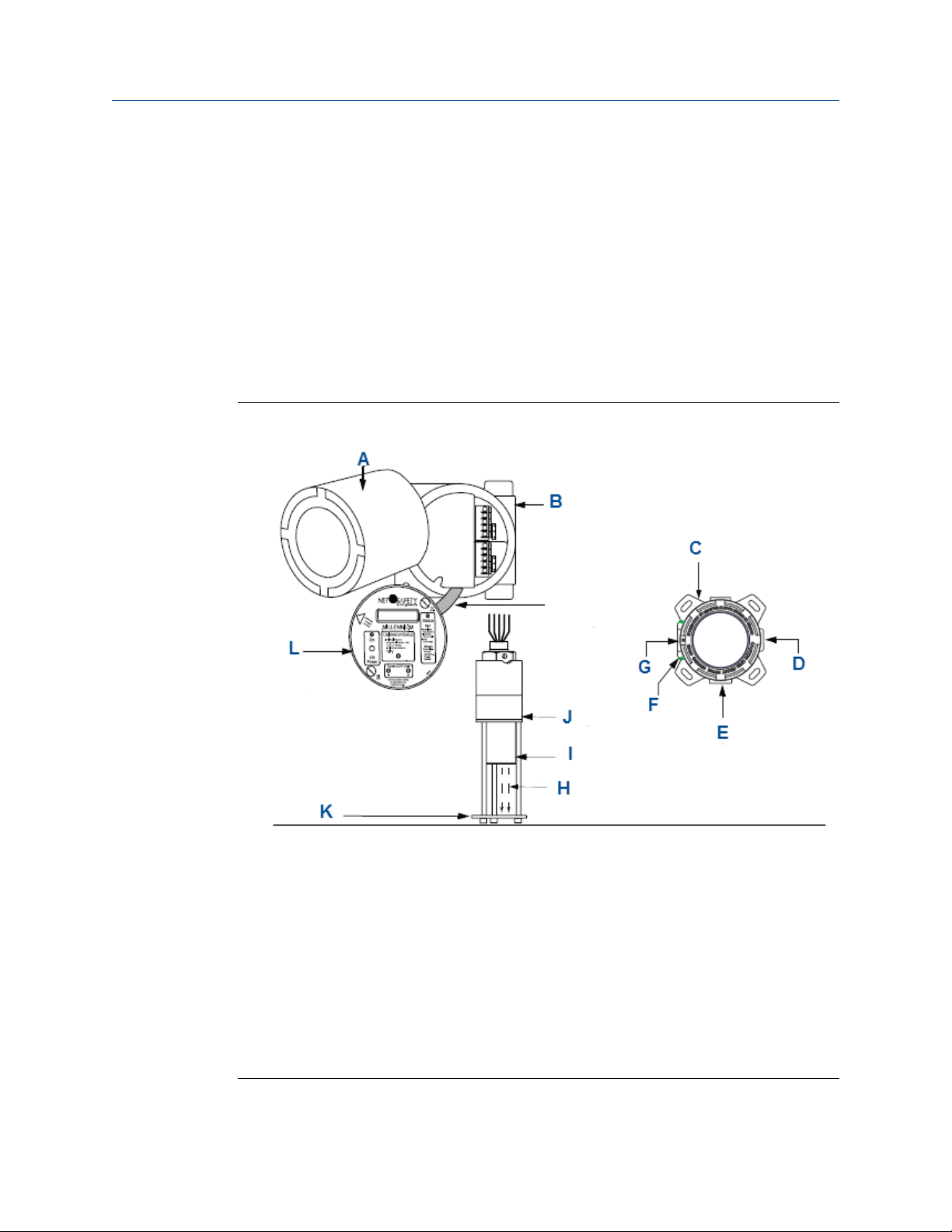
2.1 Unpacking and inspection
Carefully remove all of the components from the packaging and verify them against the
enclosed packing list. Inspect all components for any obvious damage such as broken or
loose parts. If you find any components missing or damaged, notify your local Emerson
representative or the factory immediately. Figure 2-1 outlines the components supplied
with the Net Safety APM.
Net Safety APM ComponentsFigure 2-1:
Installation
™
A. Housing cover
B. Millennium housing
C. Junction box
D. 3/4 in. NPT
E. 3/4 in. NPT
F. Earth ground screw
G. 3/4 in. NPT
H. Optical path
I. Air particle monitor (APM)
J. Internal window/sensor chamber
K. Optical path protector plate. Uncrew to clean. Refer to Section 5.2 for cleaning instructions.
L. Millennium faceplate
Reference Manual 3
Page 10

Installation
2.2 Locate sensor
Prior to the installation process, develop a location plan for placing the Net Safety APM
Sensor and Transmitter. Proper location of the Net Safety APM Sensor is essential for
providing maximum protection. The most effective placement and number of detectors
varies depending upon conditions. Consider the following points when planning the
installation.
• Carefully locate the Net Safety APM Sensor in an area where particulate may
potentially accumulate.
• Locate the Net Safety APM Sensor where it is safe from potential sources of
contamination, such as oil film, dirt, etc.
• Locate the transmitter where it will be accessible and visible.
• Mount the Net Safety APM Sensor so air currents allow particulate to flow into the
optical path of the sensor.
• If the particulate is expected to be moving horizontally due to air currents, orient the
sensor for maximum detection as shown in Figure 2-1.
• Avoid exposure to excessive heat or vibration whenever possible, because this can
cause premature failure of electronic devices.
• Seek advice from experts and refer to various regulatory publications that discuss
general guidelines for your industry.
• The Net Safety APM works off of the principle of infrared energy being reflected off
of particulate matter passing through the optical path of the Net Safety APM.
Therefore, give careful consideration when installing the Net Safety APM to ensure
that external infrared light does not reach the sensing element.
Figure 2-2 illustrates a typical installation of a Net Safety APM Sensor and Transmitter. The
Net Safety APM Sensor is mounted separately from the transmitter using the supplied
junction box. The transmitter is located at eye level, while the sensor is located where
particles are most likely to accumulate. The conduit then connects the two devices.
4 Millennium Air Particle Monitor
Page 11

Installation
Typical InstallationFigure 2-2:
A. Conduit connecting junction box and controller
B. Controller/transmitter mounted at eye level
C. Particulate matter
D. Junction box
E. Net Safety APM Sensor positioned so air current allows particulate matter to flow into sensor
F. Net Safety APM Sensor
2.3
Reference Manual 5
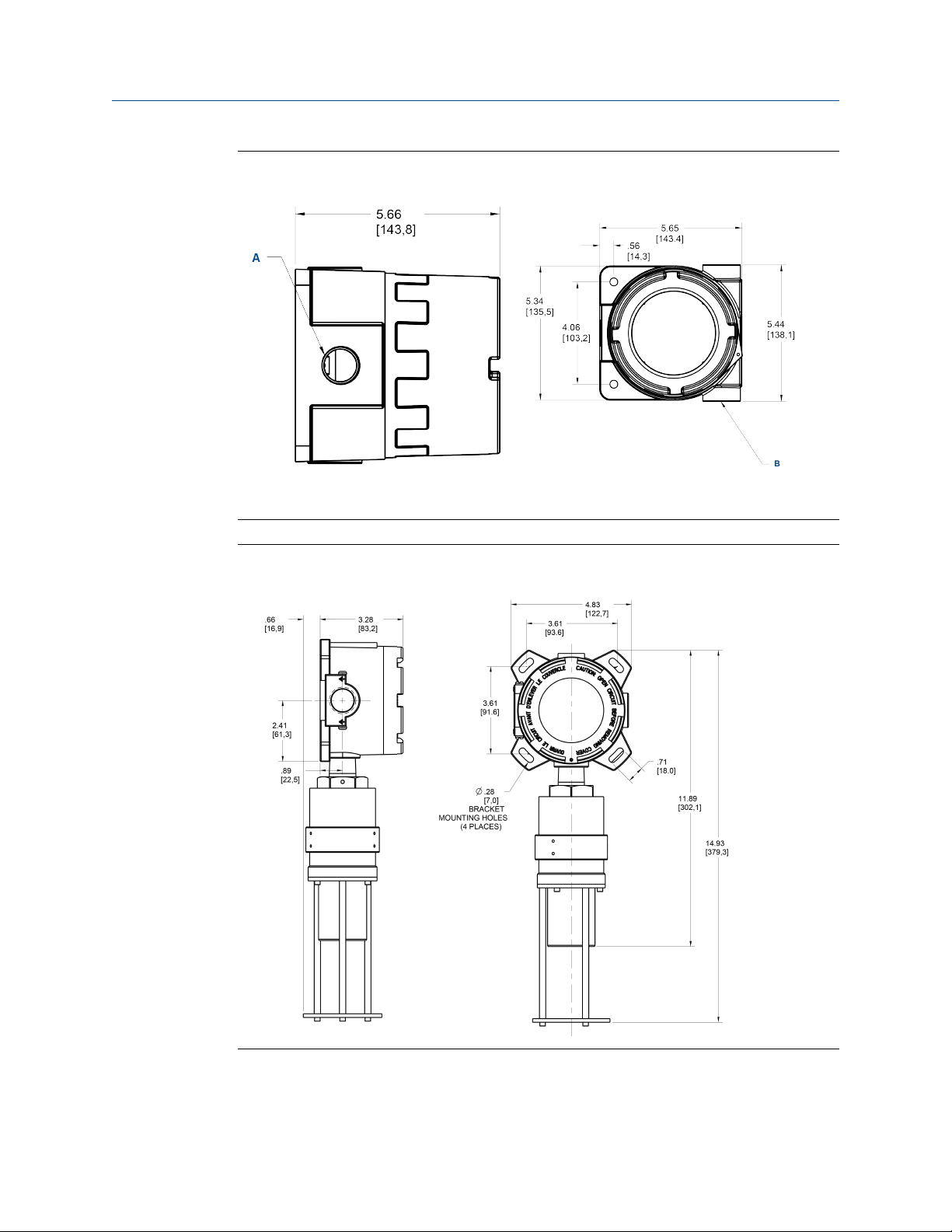
Dimensions
The following figures outline the dimensions of the Net Safety APM connected directly to
the Net Safety Millennium Transmitter (Figure 2-3) or when connected directly to the
multi-purpose junction box (Figure 2-4). There are three (3) ¾ in. NPT conduit entries
available on the Net Safety Millennium Transmitter. Adapters for M20 and ½ in. NPT
threads are also available as spare parts.
Page 12
Installation
Transmitter DimensionsFigure 2-3:
A. ¾ in. FNPT cable entry
B. ¾ in. FNPT cable
Junction Box and Sensor DimensionsFigure 2-4:
6 Millennium Air Particle Monitor
Page 13

2.4 Mount
The sensor must be mounted directly to either a transmitter or to a separate junction box
through a ¾ in. NPT conduit entry. Both the transmitter and junction boxes have mounting
holes to allow mounting to a wall or pole as desired. Mounting kit hardware is required
when mounting the transmitter or junction box to a pole. Contact your local Net Safety
representative for detailed information on the pole mounting kits.
Mount the transmitter at eye-level and make it easily accessible for monitoring and
maintenance purposes. Place the sensor where particles are likely to accumulate and
across the direction of the airflow to allow the particulates to pass through the optical
path. To prevent water damage, seal conduit at all points of entry to the transmitter or
junction box.
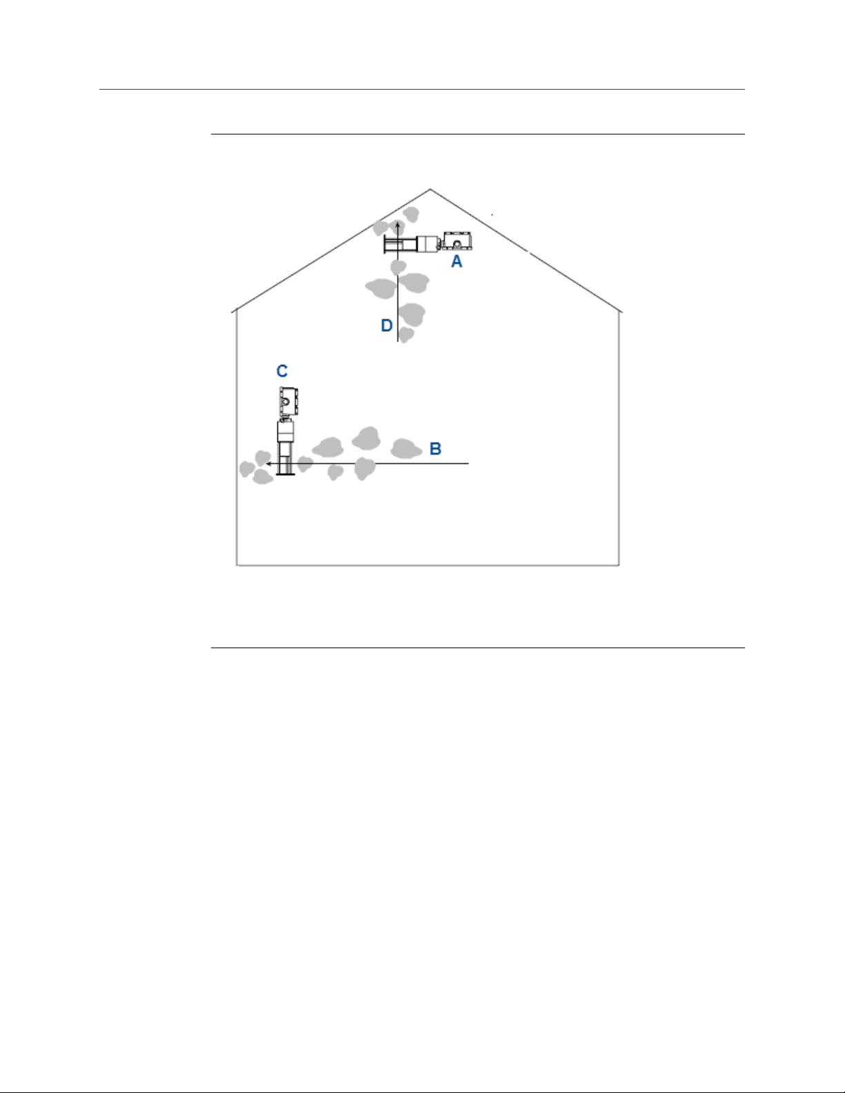
Emerson™ recommends mounting the Net Safety APM Sensor such that the air flow will
pass through the optical path of the sensor as shown in Figure 2-5.
Note
The Net Safety APM works off of the principle of infrared energy being reflected off of particulate
matter passing through the optical path of the Net Safety APM. Therefore, give careful consideration
when installing the APM to ensure that external infrared light does not reach the sensing element.
Installation
The Net Safety APM may be affected by sudden bursts of infrared light; therefore, Emerson
recommends putting a time delay (between two [2] and five [5] seconds) into the
monitoring system to prevent nuisance alarms.
Reference Manual 7
Page 14
Installation
Net Safety APM Mounting LocationsFigure 2-5:
2.4.1
A. APM sensor with junction box
B. Movement of air particulate matter
C. APM sensor with junction box
D. Movement of air particulate matter
Duct mount
Although the Net Safety Monitoring Air Particle Monitor has been proven to detect
particulate matter travelling at speeds of up to 20 meters per second (65.62 feet per
second), the detector is virtually unaffected by the velocity of particulate and air that it is
exposed to. Based on the application and the speed of the particulate matter, you can
perform a zero and adjust the sensitivity settings to suit the application.
Net Safety Monitoring recommends that the Net Safety APM be used with the UDM-001 or
UDM-002 sample draw system to acquire a cross-sectional sample of air and particulate
moving through ducts. The sample is drawn through perforations along the inlet pipe into
a chamber where the Net Safety APM is mounted. Particulate matter from the outlet pipe
is then returned to the duct. Refer to Figure 2-6 and the
UDM-001/UDM-002 reference manual (MAN-0116) for more information.
8 Millennium Air Particle Monitor
Page 15
Installation
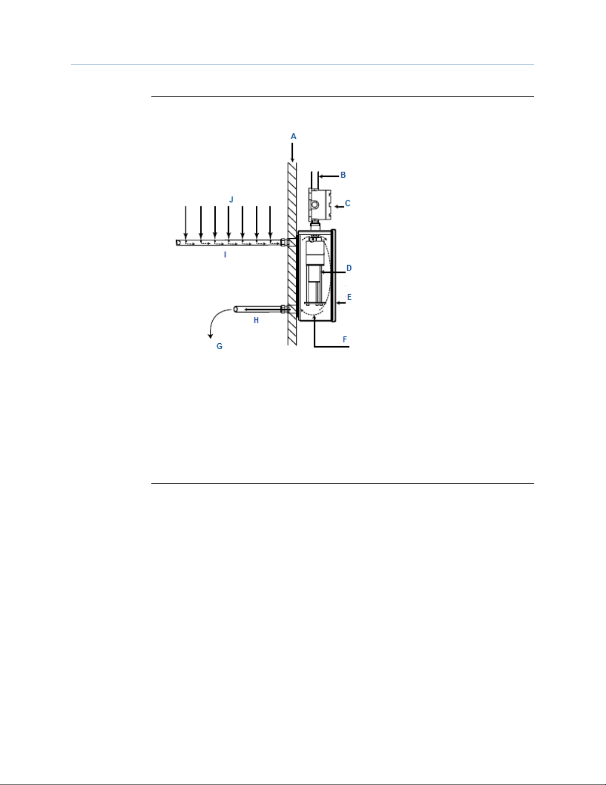
Air Flow DrawingFigure 2-6:
A. Duct surface
B. Conduit to controller
C. Junction box
D. APM sensor
E. UDM-001/UDM-002 duct mount
F. Broken lines indicate direction of air flow.
G. Direction of outlet air sample
H. Outlet pipe
I. Perforated sample draw tube (inlet pipe)
J. Direction of air sample flow
Reference Manual 9
Page 16

Installation
2.5 Wire
2.5.1 Field installation
WARNING!
ELECTRIC SHOCK
Failure to follow these installation guidelines could result in death or serious injury. Ensure that
only qualified personnel perform the installation.
Electrical shock could cause death or serious injury. Use extreme caution when making contact
with the leads and terminals.
Do not open the transmitter, sensor, or junction box enclosure when in a classified area or
when an explosive atmosphere may be present unless the power to the transmitter has been
removed.
Avoid touching electronic components as they are susceptible to electrostatic discharge (ESD).
Refer to Chapter 6 for more information.
Avoid contact with the non-metallic enclosure label as contact may create an electrostatic
charging hazard.
2.5.2
NOTICE
Wiring codes and regulations may vary. ATEX requires that supply connections wiring must be
rated at least 5 °C (41 °F) above the maximum ambient temperature of 85 °C (185 °F). Wiring
must comply with all applicable regulations relating to the installation of electrical equipment
in a hazardous area and is the installer's responsibility. If in doubt, consult a qualified official
before wiring the system.
When separating the sensor from the transmitter, Emerson highly recommends the use of
shielded cable to protect against interference caused by extraneous electrical or
electromagnetic noise to meet mandatory CE mark electromagnetic compatibility (EMC)
requirements. In applications where the wiring is installed in conduit, the conduit must not
be used for wiring to other equipment.
Seals
Emerson recommends using seals to further protect the system against any unwanted
water ingression and installing equipment according to applicable local electrical codes.
Emerson especially recommends seals for installations that use high-pressure or steam
cleaning devices in proximity to the transmitter and/or sensor.
• Emerson recommends water-proof and explosion-proof conduit seals to prevent
water accumulation within the enclosure.
• Locate seals as close to the device as possible and not more than 18 inches (46 cm)
away.
• Explosion-proof installations may require an additional seal where conduit enters a
non-hazardous area. Ensure conformity with local wiring codes.
10 Millennium Air Particle Monitor
Page 17

• When pouring a seal, use a fiber dam to assure proper formation of the seal. Never
pour seals at temperatures below freezing.
• Strip back the jacket and shielding of the cable to permit the seal to form around the
individual wires. This will prevent air, particles, and water leakage through the inside
of the shield and into the enclosure.
• Emerson recommends using explosion-proof drains and conduit breathers. In some
applications, alternate changes in temperature and barometric pressure can cause
breathing which allows moist air to enter and circulate inside the conduit. Joints in
the conduit system are seldom tight enough to prevent this breathing.
2.5.3 Sensor separation
Since the Net Safety APM Sensor must be located where it will pick up particulate in an air
flow, and the transmitter where it can be easily reached, it is often necessary to separate
the transmitter and sensor. This is done with the aid of the included sensor separation kit
(SEP). This kit is composed of a junction box and terminal strip. Refer to the
Net Safety Multi-purpose Junction Box manual (MAN-0081) for terminal designation.
The maximum separation distance between the sensor and the transmitter is limited by
the resistance of the connecting wiring, which is a function of the gauge of wire being
used. Net Safety recommends that sensor separation must not exceed 610 m (2,000 ft)
while using 16 AWG (1.31 mm2) wire. Refer to Chapter 7 for wire gauges and resistance
values.
Installation
2.5.4
Note
When the sensor is separated from the transmitter, always ensure that the transmitter is supplying
the required voltage to the sensor terminals inside the junction box. If the 4-20 mA signal is not used,
connect a jumper between the 4-20 terminal and the COM terminal on the transmitter terminal
board.
Board assembly
There are three different fixed boards and a relay board which make up the PCB assembly.
Simply loosen the three locking standoffs, remove one board, insert the other board, and
tighten screws. The boards are susceptible to electrostatic discharge (ESD). Refer to
Chapter 6 for further information on proper handling of this equipment.
Reference Manual 11
Page 18
Installation
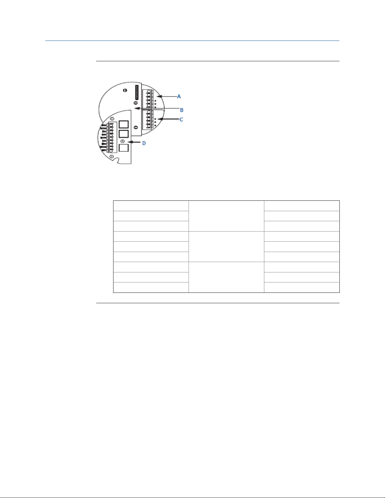
Net Safety Millennium Transmitter Module BoardsFigure 2-7:
A. Terminal board
B. Option board
C. Sensor board
D.
PNO Fault Normally open
PCOM Common
PNC Normally closed
LNO Clean window (low) Normally open
LCOM Common
LNC Normally closed
HNO Alarm Normally open
HCOM Common
HNC Normally closed
Electromechanical Relay BoardTable 2-1:
2.5.5 Installation to transmitter or junction box
The Net Safety APM sensor is supplied with a ¾ in. NPT male conduit connection and is
intended to be mounted directly to an available ¾ in. NPT conduit entry on the Net Safety
Millennium Transmitter or remotely using the supplied junction box.
Tightly thread the sensor to the transmitter or junction box. A minimum of seven (7)
threads need to be engaged to ensure proper water ingress protection and the explosion
proof rating of the devices. Take proper care to ensure that no damage is caused to the
wires on the Net Safety APM Sensor and circuit board inside the transmitter and junction
box.
Emerson recommends using conductive grease on the threads.
The sensor can be mounted in a number of configurations to ensure that air particulate will
pass through the optical path of the sensor. Emerson recommends that the APM be
mounted horizontally to ensure that build-up of dirt, dust, and debris will not affect the
operation of the sensor.
12 Millennium Air Particle Monitor
Page 19

2.5.6 Faceplate rotation
In some applications, it is necessary for the Net Safety Millennium Transmitter to be
mounted in a non-standard orientation. To accommodate such installations and ensure
that the display will appear at the correct angle for viewing, you can rotate the PCB
assembly inside the transmitter’s housing. Figure 2-8 outlines non-standard orientations of
the Net Safety Millennium Transmitter.
Non-standard OrientationFigure 2-8:
WARNING!
Installation
Do not open the transmitter, sensor, or junction box enclosure when in a classified area or
when an explosive atmosphere may be present unless the power to the transmitter has been
removed.
The following section describes the steps required to rotate the Net Safety Millennium
Transmitter faceplate. Refer to Figure 2-9 for the components in the transmitter housing.
The boards may be susceptible to ESD. Refer to Chapter 6 for further information on proper
handling of this equipment.
Procedure
1. Remove the transmitter housing cover.
2. Turn the power to the transmitter off.
3. Unscrew both the knobs marked Pull Here.
4. Lift the transmitter faceplate from the housing and allow to the faceplate to hang
from the ribbon cable.
5. Unscrew the two metal standoffs.
6. Carefully remove the PCB assembly from the housing.
The rotator plate is secured to the bottom of the housing and is accessible after the
PCB assembly has been removed.
7. Rotate the PCB assembly to the desired position and line up the standoffs with the
mounting holes.
8. Insert standoffs in the appropriate horizontal or vertical mounting holes.
9. Tighten standoffs to secure the PCB assembly.
10. Replace faceplate and tighten Pull Here knobs.
11. Return power to the detector and replace the housing cover.
Reference Manual 13
Page 20

Installation
PCB Assembly RotatedFigure 2-9:
2.5.7
A. Horizontal mounting holes
B. Faceplate
C. Ribbon cable
D. Standoffs
E. PCB assembly
F. Vertical mounting holes
General requirements
WARNING!
EXPLOSION
Do not open the transmitter, sensor, or junction box enclosure when in a classified area or
when an explosive atmosphere may be present unless the power to the transmitter has been
removed.
When connecting cable wires, use a small screwdriver to gently press down and hold the
spring connector open. Insert the appropriate wire into the open connector hole, releasing
the screwdriver to secure the wire as shown in Figure 2-10.
The connector accomodates wire sizes between 14 and 20 AWG.
14 Millennium Air Particle Monitor
Page 21

Installation
Terminal ConnectionFigure 2-10:
2.5.8 Wiring sensor to transmitter
Connect the sensor wires to the Net Safety Millennium Transmitter as shown in Figure 2-11.
Table 2-2 outlines the wire colors and their purpose.
Sensor Wire Colors and Terminal DefinitionTable 2-2:
Wire color White Blue Red Black Shield
Marking +24 Vdc Sig A Sig B COM(-) Shld
Function 10.5-32 Vdc connec-
tion
Communication sig-
nal A
Communication sig-
nal B
Common / supply
ground
Earth
ground
Reference Manual 15
Page 22

Installation
Millennium sensor wiringFigure 2-11:
A. Terminal board
B. RST
+24 V
COM
4-20
ISO
C. Wht
Blu
Red
Blk
Shld
D. APM sensor wires
E. APM sensor
F. Sensor board
G. Sensor terminals
H. Power terminals
16 Millennium Air Particle Monitor
Page 23

2.5.9 Wire sensor to junction box
Sensor wiring side refers to wiring between the sensor and junction box. Transmitter
wiring side refers to wiring between the Net Safety Millennium (MLP) Transmitter and
junction box.
Junction Box Wiring (Model JB-MPD)Figure 2-12:
A. Resistor - 120 ohms
B.
Transmitter WiringTable 2-3:
Installation
Terminal Function/marking
1 (GND) Earth ground
2 Vdc (+)
3 COM (-)
4 Sig A
5 Sig B
6 Not used
7 Not used
C.
Terminal Color Function
1 (GND) Green Earth ground
2 White Vdc (+)
3 Black COM (-)
4 Blue A (communication)
5 Red B (communication)
6 N/A Not used
7 N/A Not used
Sensor WiringTable 2-4:
Note
Shield should be terminated at earth ground at panel/PLC/DCS/RTU
Reference Manual 17
Page 24

Installation
2.5.10 Wiring transmitter to control system
Connect the Net Safety Millennium Transmitter to the control system as shown in
Figure 2-11. Table 2-5 outlines the terminal marking and their purpose.
Transmitter ConnectionsTable 2-5:
Marking RST +24V COM 4-20 +VISO
Function Remote reset 10.5-32 Vdc
Connection
Common / supply
ground
Current loop output
(mA)
+24 Vdc isolated
4-20 power
2.5.11 External ground
In order to ensure proper operation of the sensor, an external earth ground is
recommended. Net Safety recommends that the external ground be connected to the
grounding point on the enclosure. Refer to Figure 2-13 for grounding connection location.
External grounding pointFigure 2-13:
A. External grounding
2.6
18 Millennium Air Particle Monitor
Current output
To set the current output, simply move the jumper located on the terminal board near the
power terminals, to the isolated or non-isolated current position. Refer to Figure 2-14.
Page 25

Installation
Note
Unless otherwise specified, all models ship with this jumper in the non-isolated current position (Pin
2 and Pin 3 jumped). Refer to Figure 2-14.
Jumper LocationsFigure 2-14:
2.7
A. Jumper positions to set power source for current output.
Isolated and non-isolated current jumper - place jumper (shorting jack) over Pin 3 and Pin 2
(default position) for non-isolated configuration (source).
B. Place jumper over Pin 1 and Pin 2 for remaining configurations. Refer to Figure 2-1.
Non-isolated and isolated power configurations
For current source using non-isolated configuration, the jumper must remain in the default
position (Pin 2 and Pin 3 jumped). The jumper is placed over Pin 1 and Pin 2 for current sink
using non-isolated configuration.
For isolated configuration using a separate power supply to isolate the current loop, the
jumper must be placed over Pin 1 and Pin 2 for source and sink. Refer to Figure 2-15,
Figure 2-16, Figure 2-17, and Figure 2-16.
Note the jumper position for each configuration.
Reference Manual 19
Page 26

Installation
Detector Non-Isolated Configuration (Source)Figure 2-15:
A. Isolated and non-isolated jumper pins
Detector Non-Isolated Configuration (Sink)Figure 2-16:
A. Isolated and non-isolated jumper pins
20 Millennium Air Particle Monitor
Page 27

Detector Isolated Configuration (Source)Figure 2-17:
A. Isolated and non-isolated jumper pins
Detector Isolated Configuration (Sink)Figure 2-18:
Installation
A. Isolated and non-isolated jumper pins
2.8
Reference Manual 21
Installation checklist
Review the following checklist prior to turning the power on to the transmitter after
installation has been completed:
• Ensure that the transmitter and sensor are properly and firmly mounted.
• Ensure that stopping plugs are securely tightened on any unused conduit entries.
• Ensure that the transmitter and sensor are not obstructed, such that they are
accessible and the particulate matter is not inhibited from reaching the sensors
optical path.
• Ensure adherence to applicable local guidelines and requirements on wiring and
sealing of equipment in hazardous and non-hazardous areas.
Page 28

Installation
• Ensure that proper shielding and grounding practices are adhered to and local codes
are being followed.
• Check system operational voltage and conditions and ensure that they are within
the applicable specifications of the transmitter and sensor.
• Verify wiring at all termination and junction points (transmitter, junction box, and
power supply).
• Ensure that the transmitter housing cover and sensor cap are tightly secured.
22 Millennium Air Particle Monitor
Page 29

3 Operation
3.1 Net Safety™ Millennium Transmitter
WARNING!
EXPLOSION
Do not open the transmitter, sensor, or junction box enclosure when in a classified area or
when an explosive atmosphere may be present unless the power to the transmitter has been
removed.
Figure 3-1 outlines the components on the Net Safety Millennium Transmitter, and the
subsequent sections provide explanations for each component.
Net Safety Millennium Transmitter LayoutFigure 3-1:
Operation
A. Section 3.1.1, Display
B. Section 3.1.2, Status
C. Section 3.1.4, Setup
D. Section 3.1.6, Current output
E. Section 3.1.3, On/off
F. Section 3.1.5, Magnetic Reed switch
Reference Manual 23
Page 30

Operation
3.1.1 Display
A scrolling 8 character display is provided to show various status messages and prompts.
Refer to Table 3-1 for the various display messages.
3.1.2 Status LED
The status LED is used to provide visual indication as to the status of the transmitter and
sensor. Refer to Section 3.2 for specific status conditions of the LED.
3.1.3 On/Off switch
The On/Off switch is used to turn power on and off to the transmitter and sensor. As the
transmitter’s housing must be opened to access the On/Off switch, the area where the
transmitter is located must be de-classified prior to using.
3.1.4 Setup button
The Setup button provides access to the Net Safety Millennium Transmitter’s main menu,
which in turn allows options to be reviewed and set. The Setup button is also used to zero
the sensor. As the transmitter’s housing must be opened to access the button, the area
must be de-classified before using. Refer to Chapter 4 for instructions on programming the
Net Safety Millennium Transmitter.
3.1.5
3.1.6
Magnetic Reed switch
Emerson provides the magnetic Reed switch to avoid opening the housing in an
environment where gas may be present. The magnetic Reed switch functions in the same
manner as the Setup button but in a non-intrusive manner. The magnet comes
permanently attached to the side of the transmitter.
Current output check
Current output check test jacks are provided to facilitate current loop measurements
without breaking external current loop. To take current loop measurements, ensure wiring
is correct and current loop is closed, and then follow steps below
• Set meter on mA scale and insert meter leads into test jacks.
• Put external devices in bypass, if necessary, to avoid unwanted alarm response.
• Perform simulated tests to check output.
• Remove meter leads from test jacks and return external devices to normal.
24 Millennium Air Particle Monitor
Page 31

3.2 Indications and outputs
Transmitter IndicationsTable 3-1:
State Current Output Status LED Display
Main menu entered 3.0 mA Solid green Main menu items
Normal operation 4.0 mA Green blip Clear
Startup delay 3.0 mA Slow red flash Start delay
Dirty optics 3.3 mA Fast red flash Dirty chamber
Particulate present 20 mA Red blip Alarm
Fault condition 2.5 mA Fast red flash Fault
Updating Net Safety APM
Sensor
3.0 mA Slow red flash Busy
3.3 Alarms
Operation
3.3.1 Net Safety APM fault
To ensure proper response, the Net Safety Millennium features self-testing circuitry that
continuously checks for problems. When power is applied, the system automatically
begins a test to ensure proper functionality.
During normal operation, the transmitter continuously monitors the signal from the
internal APM source. If the transmitter determines that the APM program is not running
correctly, it will reset the Net Safety APM Sensor.
3.3.2
Clean window/dirty chamber
Over an extended period, oily film or particulate build-up on the sensor window may
obscure the detector. When dirty, the Clean window alarm trips, the message Dirty
Chamber displays, the Status LED flashes fast red, and the current output is 3.3 mA. Refer
to Section 4.3.2 to define the clean window sensitivity and Section 5.2 on cleaning the Net
Safety APM window.
Reference Manual 25
Page 32

Operation
3.3.3 Particulate alarm
When particulate is present in the Net Safety APM’s chamber, the message Alarm
displays, the Status LED blips red, and the current output is 20.0 mA. If the relay has been
set to non-latching, the unit resets itself; if set to latching, a manual or remote reset is
required to clear the alarm condition. Refer to Section 3.4.
Note
The Net Safety APM may be affected by sudden bursts of infrared light; therefore, Emerson
recommends that a time delay [between two (2) and five (5) seconds] be put into the monitoring
system to prevent nuisance alarms.
3.4 Reset
3.4.1 Remote reset
The Net Safety Millennium is capable of remote reset. A normally open push-button switch
must be connected between the RST terminal and the COM terminal on the terminal
board. If relay is set to Latching, a remote reset is possible.
3.4.2 Manual reset
If a relay is set to Latching, a manual reset is required to clear the alarm condition. Simply
place and hold the magnet against the Reed switch or press and hold Setup for 3-5
seconds. The unit returns to normal operation.
3.5
3.6
Normal
With no particulate present and no fault detected, the display reads Clear, Status LED
blips/blinks green, and the current output is 4.0 mA.
Outputs
3.6.1 Relays
All relay outputs have FORM-C SPDT contacts rated 5 amperes at 30 Vdc/250 Vac. Relays
are dry contacts.
26 Millennium Air Particle Monitor
Page 33

3.6.2 Current
A 4-20 mA dc current output is used to transmit the alarm status and fault conditions to
other devices. This output can be wired for isolated or non-isolated operation. A 4.0 mA
output indicates normal operation; a 20.0 mA output indicates that the alarm threshold
has been exceeded. Current output of 2.5 mA indicates the presence of a system fault.
Current output of 3.3 mA indicates a build-up of particulate in the sensor’s chamber or
dirty window. Refer to Section 3.2 for additional indications and outputs.
3.7 Net Safety APM Sensor
3.7.1 Sensor power up
When the transmitter applies power to the sensor, a warm-up routine begins, and the
sensor is automatically tested to ensure proper functioning. The warm-up time for the Net
Safety APM Sensor is typically one hundred fifty (150) seconds. After the warm-up cycle
has completed, the display reads Clear.
Operation
3.7.2
As part of the self-diagnostic routine of the Net Safety Millennium Transmitter, the analog
output outputs 20 mA on initial power up for a period not greater than 450 milliseconds. If
routine power loss is expected on the system, take appropriate actions to limit false alarm
conditions due to this diagnostic routine.
Sensor communication
The Net Safety APM Sensor uses a proprietary protocol to communicate with the Net
Safety Millennium Transmitter. Never connect the Net Safety APM Sensor to any device
other than a Net Safety Millennium Transmitter. If any problems develop, please refer to
Section 5.3.
Reference Manual 27
Page 34

Operation
28 Millennium Air Particle Monitor
Page 35

4 Programming
4.1 Main menu
The main menu provides access to various functional settings and viewing of current
settings. The following options/settings are available in the main menu.
• Set Zero
• Sensitivity Settings
• Review Relay Settings
• Set Relay Options
• Select Display Language
4.2 Accessing the main menu
Programming
4.3
There are two ways to access the main menu: using the Setup button on the faceplate of
the transmitter or using the magnetic Reed switch.
• Press and hold the Setup button to access the main menu.
• Place and hold the magnet to the transmitter’s housing (10 o’clock position as
shown in Figure 3-1) to access the main menu.
Using the main menu
The following steps outline the actions required to navigate through the menu system.
Refer to Figure 4-1 for the programming flow chart for the Net Safety Millennium
Transmitter.
Reference Manual 29
Page 36

Programming
Programming FlowchartFigure 4-1:
Prerequisites
Ensure that the transmitter is turned on and that no fault is present. If a fault is present, the
menu system isn't accessible.
Procedure
1. Press and hold Setup or hold the magnet next to the triangle on the faceplate as
shown in Figure 3-1 until the message Switch On displays and the countdown (10
to 0) finishes.
30 Millennium Air Particle Monitor
Page 37

2. To set/view an option, press Setup or place the magnet to the Reed switch at the
4.3.1 Zero
If at any time the background particulate levels change, the transmitter may be zeroed to
the new levels. Emerson recommends zeroing every 3 months.
Programming
An option scrolls across the display followed by the prompt YES?
YES? prompt. If you do not wish to select that option, wait five (5) seconds until the
next option appears and then select YES?.
A selection is acknowledged with a flashing YES.
If no option is selected, the transmitter returns to the normal operational mode, and
the display reads Clear.
Important
When the menu system has been entered, the current output changes to 3 mA. Ensure that
external systems are bypassed, as required, prior to entering the menu system.
Important
After initial power-up, allow the unit to warm up for two to four hours before zeroing.
If the sensor has been in operation for a period of time, Emerson recommends that you
clean the window as outlined in Section 5.2.
Be sure the Net Safety APM is energized up and is not indicating a fault; e.g. the display
reads Clear, the status LED is blinking green, and the current output is 4.0 mA.
Prior to beginning the zeroing procedure, ensure that the air surrounding the Net Safety
APM is clean and free of particulate or at the accepted background level for the specific
application.
The following steps outline the procedure to perform a zero of the Net Safety APM Sensor.
Procedure
1. Press and hold Setup or the magnet to the Reed switch to enter the main menu; wait
for the countdown, from 10 to 0, to end.
2. Release Setup or remove the magnet from the Reed switch.
The current output moves to 3.0 mA.
3. When Set Zero and then YES? is displayed, press Setup or use the Reed switch to
select this option.
A flashing YES confirms your selection.
The Net Safety APM has now been zeroed, meaning that the existing level of air
contamination is considered normal.
Reference Manual 31
Page 38

Programming
Tip
If your application has a constant level of particulate present that is required to be ignored by the
APM you can set the zero level with the known particulate present as shown in Figure 4-2.
To further fine tune the Net Safety APM response for your requirements, adjust the
sensitivity settings accordingly. Refer to Section 4.3.2.
Zero Level SettingFigure 4-2:
4.3.2 Sensitivity settings
The Net Safety APM can be set to detect low, medium or high sensitivity levels with high
being the most sensitive. By default the sensitivity is set for high sensitivity from the
factory. Follow the steps below to change the sensitivity.
1. Press and hold Setup or the magnet to the Reed switch to enter the main menu; wait
for the countdown, from 10 to 0, to end.
2. Release Setup or remove the magnet from the Reed switch.
The current output moves to 3.0 mA.
3. When Sensitivity Settings and then YES? is displayed, press Setup or use
the Reed switch to select this option.
A flashing YES confirms your selection.
32 Millennium Air Particle Monitor
Page 39

4. The following three options display: Low Sensitivity YES? , Medium Sensitivity YES? and
High Sensitivity YES?
5. When the required setting is displayed, press Setup button or use the Reed switch to
select.
The selection is acknowledged with a flashing YES.
4.3.3 Review relay settings
This is a read-only mode to provide a summary of the relay settings. Changes to the relay
settings cannot be made in this menu item.
Procedure
1. Press and hold Setup or the magnet to the Reed switch to enter the main menu; wait
for the countdown, from 10 to 0, to end.
2. Release Setup or remove the magnet from the Reed switch.
The current output moves to 3.0 mA.
3. When Review Relay Settings and then YES? is displayed, press Setup or use
the Reed switch to select this option.
Programming
4.3.4
A flashing YES confirms the selection, and the settings are displayed.
Set relay options
This section outlines how to change the normal operation of the Clean Window and Alarm
relays.
Follow the steps below to alter the relay functions or refer to Figure 4-1.
Note
The Fault Alarm relay settings are fixed as normally Energized and Non-Latching and are not adjustable
within the menu system.
Procedure
1. Press and hold Setup or the magnet to the Reed switch to enter the main menu; wait
for the countdown, from 10 to 0, to end.
2. Release Setup or remove the magnet from the Reed switch.
The current output moves to 3.0 mA.
3. When Set Relay Options and then YES? is displayed, press Setup or use the
Reed switch to select.
A flashing YES confirms your selection. The message Set Clean Window Alarm
and then YES? are displayed.
4. Press Setup or use the Reed switch to select this option.
Reference Manual 33
Page 40

Programming
The flashing YES confirms this selection. After the Clean Window Alarm option has
been chosen, the message Coil Status is displayed followed by Energized
YES?.
5. To select that the relay be energized under normal conditions, press Setup or use
the Reed switch to select this option.
To select that the relay be de-energized under normal conditions wait five (5)
seconds for the next selection. If Energized has been selected, a flashing YES
confirms the selection.
6. To select that the relay be de-energized under normal conditions, press Setup or use
the Reed switch to select this option.
If the relay is setup as required, wait five (5) seconds for the next selection.
If De-energized has been selected, a flashing YES confirms the selection.
The display now shows Latch Status, followed by Latching YES?.
7. To select that the relay be latched in its alarm state, press Setup or use the Reed
switch to select this option.
To select that the relay be non-latching, wait five (5) seconds for the next selection.
If latching has been selected, a flashing YES confirms the selection.
8. To select that the relay be non-latching, press Setup or use the Reed switch to select
this option.
If the relay is setup as required, wait five (5) seconds for the next selection. If you
selected Non-latching, a flashing YES confirms the selection.
The message Set Alarm and then YES? are displayed.
9. Press Setup or use the Reed switch to select this option.
A flashing YES confirms this selection. After the Set Alarm option has been chosen,
the message Coil Status is displayed, followed by Energized YES?.
10. To select that the relay be energized under normal conditions, press Setup or use
the Reed switch to select this option.
To select that the relay be de-energized under normal conditions, wait five (5)
seconds for the next selection. If you selected Energized, a flashing YES confirms the
selection.
11. To select that the relay be de-energized under normal conditions, press Setup or use
the Reed switch to select this option.
If the relay is setup as required, wait five (5) seconds for the next selection. If you
selected De-energized, a flashing YES confirms the selection.
The display now shows Latch Status, followed by Latching YES?.
34 Millennium Air Particle Monitor
Page 41

12. To select that the relay be latched in its alarm state, press Setup or use the Reed
switch to select this option.
To select that the relay be non-latching, wait five (5) seconds for the next selection.
If you selected Latching, a flashing YES confirms the selection.
13. To select that the relay be non-latching, press Setup or use the Reed switch to select
this option.
If the relay is setup as required, wait five (5) seconds for the next selection. If you
selected Non-latching, a flashing YES confirms the selection.
4.3.5 Select display language
This section outlines how to change the main display language to English, Spanish, or
French. Follow the steps below to change the display language.
1. Press and hold Setup or the magnet to the Reed switch to enter the main menu; wait
for the countdown, from 10 to 0, to end.
2. Release Setup or remove the magnet from the Reed switch.
The current output moves to 3.0 mA.
3. When Select Display Language and then YES? is displayed, press Setup or
use the Reed switch to select.
Programming
A flashing YES confirms your selection. The messages English and then YES? are
displayed.
4. Press Setup or use the Reed switch to select this option.
The flashing YES confirms this selection.
5. If English is not the desired language, wait five (5) seconds for the next selection.
The message Espanol and then YES? are displayed.
6. Press Setup or use the Reed switch to select this option.
The flashing YES confirms this selection.
7. If Spanish is not the desired language, wait five (5) seconds for the next selection.
The messages Francais and then YES? are displayed.
8. Press Setup or use the Reed switch to select this option.
The flashing YES confirms this selection.
9. If French is not the desired language, wait five (5) seconds for the next selection.
Reference Manual 35
Page 42

Programming
36 Millennium Air Particle Monitor
Page 43

5 Maintenance
5.1 Response check
Emerson™ recommends that you check and test the Net Safety™ APM at least once every
three months.
Spray Smoke Detector Tester (or equivalent product) in the direction of the sensor from a
distance of two feet. Typically, a one to two second burst is adequate to initiate an alarm.
When the alarm activates, the display reads Alarm, the Status LED flashes red, and the
current output is 20.0 mA to indicate detection of particulate matter or canned
contaminant.
After simulation, reset the alarm if latched as outlined in Section 3.4 and zero the Net
Safety APM as per Section 4.3.1 in clear air free of particulates or at the accepted
particulate background level for the specific application.
Maintenance
5.2
CAUTION!
EQUIPMENT DAMAGE
The overuse of artificial particulate detector testers or spraying from too close a range may
impair the operation of the Net Safety APM due to the accumulation of an oily film on the
internal window.
Cleaning
Clean the Net Safety APM sensor routinely. The frequency of cleaning depends on the
application and environment where the Net Safety APM is installed.
When the Dirty Chamber or Clean Window Alarm message is displayed, the lens /
window and chamber require cleaning. Follow the steps below when cleaning.
Procedure
1. Turn off power to the transmitter.
2. Unscrew bolts at the end of circular plate and connecting rods.
3. Using conventional multi-purpose or glass cleaning solution, clean the inner sides of
the sensor chamber and front side of the lens / window.
Use a lint-free towel or sponge to apply the cleaning solution.
4. Ensure that there is no residue left on the lens or window.
5. Put the circular plate back into position, ensuring that the textured surface faces the
Net Safety APM window, and screw in the bolts at the end of the connecting rods.
6. Return power to the Net Safety APM and check for normal operation.
Reference Manual 37
Page 44

Maintenance
7. Complete the Zero procedure (Section 4.3.1) to establish new settings.
If problems develop and persist, contact the Net Safety Service department or refer
to Section 1.3 (Return of material).
5.3 Troubleshooting
The Net Safety Millennium Transmitter and Net Safety APM Sensor are not designed to be
repaired in the field. If a problem should develop, carefully check for faulty wiring. If it is
determined that the problem is caused by an electronic defect, return the device to the
factory for repair (refer to Section 1.2 and Section 1.3 for instructions).
Perform regular checks on the unit around every two to three months to ensure desired
operation. Refer to Section 5.1 for instructions.
5.4 Storage
Store the sensor and its electronic components/parts in locations free from dust and
moisture. Ensure that the storage temperature is well within the limits of the certified
temperatures of the equipment. See Chapter 8 for storage temperatures.
5.5
Spare parts and accessories
Spare Parts and AccessoriesTable 5-1:
Description Part Number
Universal duct mount assembly with 3.3 ft. (1 m) inlet sampling tube UDM-001
Universal duct mount assembly with 4.9 ft. (1.5 m) inlet sampling tube UDM-002
Universal duct mount assembly UDM-003
Magnet assembly HDW-0118
Replacement Millennium transmitter board ML7-TX700
Terminal board for JB-MPD JB-MPD-PCBA
316 stainless steel termination junction box JB-MPD-S
Conduit reducer - ¾ in. (19 mm) to M20 - nickel-plated brass HDW-0148
Conduit reducer - ¾ in. (19 mm) to M20 - stainless steel HDW-0147
38 Millennium Air Particle Monitor
Page 45

6 Electrostatic sensitive device
Electrostatic discharge (ESD) is the transfer, between bodies, of an electrostatic charge
caused by direct contact or induced by an electrostatic field.
The most common cause of ESD is physical contact. Touching an object can cause a
discharge of electrostatic energy. If the charge is sufficient and occurs near electronic
components, it can damage or destroy those components. In some cases, damage is
instantaneous, and an immediate malfunction occurs. However, symptoms are not always
immediate—performance may be marginal or seemingly normal for an indefinite period of
time, followed by a sudden failure.
To eliminate potential ESD damage, review the following guidelines:
• Handle boards by the sides — taking care not to touch electronic components.
• Wear grounded wrist or foot straps, ESD shoes, or heel grounders to dissipate
unwanted static energy.
• Prior to handling boards, dispel any charge in your body or equipment by touching a
grounded metal surface.
• Ensure all components are transported and stored in ESD safe packaging.
• When returning boards, carefully package in the original carton and static protective
wrapping.
• Ensure all personnel are educated and trained in ESD control procedures.
• Clean off the housing with a damp cloth only.
Electrostatic sensitive device
In general, exercise accepted and proven precautions normally observed when handling
electrostatic sensitive devices.
Reference Manual 39
Page 46

Electrostatic sensitive device
40 Millennium Air Particle Monitor
Page 47

7 Wire resistance table
Wire resistance table
Distance
Meters (Feet)
30.5 (100) 1.02 0.64 0.40 0.25
61 (200) 2.03 1.28 0.80 0.51
91.4 (300) 3.05 1.92 1.20 0.76
121.9 (400) 4.06 2.55 1.61 1.01
152.4 (500) 5.08 3.20 2.01 1.26
182.9 (600) 6.09 3.83 2.41 1.52
213.4 (700) 7.11 4.47 2.81 1.77
243.8 (800) 8.12 5.11 3.21 2.02
274.3 (900) 9.14 5.75 3.61 2.27
304.8 (1,000) 10.20 6.39 4.02 2.53
381 (1,250) 12.70 7.99 5.03 3.16
457.2 (1,500) 15.20 9.58 6.02 3.79
533.4 (1,750) 17.80 11.20 7.03 4.42
609.6 (2,000) 20.30 12.80 8.03 5.05
685.8 (2,250) 22.80 14.40 9.03 5.68
762 (2,500) 25.40 16.00 10.00 6.31
914.4 (3,000) 30.50 19.20 12.00 7.58
1066.8 (3,500) 35.50 22.40 14.10 8.84
41292.2 (4,000) 40.60 25.50 16.10 10.00
1371.6 (4,500) 45.70 28.70 18.10 11.40
5,000 (1,524) 50.10 32.00 20.10 12.60
1676.4 (5,500) 55.80 35.10 22.10 13.91
1828.8 (6,000) 61.00 38.30 24.10 15.20
1981.2 (6,500) 66.00 41.50 26.10 16.40
2133.6 (7,000) 71.10 44.70 28.10 17.70
2286 (7,500) 76.10 47.90 30.10 19.00
2438.4 (8,000) 81.20 51.10 23.10 20.20
2743.2 (9,000) 91.40 57.50 36.10 22.70
3048 (10,000) 102.00 63.90 40.20 25.30
AWG #20
0.5 mm
AWG #18
2
0.8 mm
2
AWG #16
1.0 mm
AWG #14
2
2.0 mm
2
Resistance shown is one way. This figure must be doubled when determining closed loop
resistance.
Reference Manual 41
Page 48

Wire resistance table
42 Millennium Air Particle Monitor
Page 49

Specifications
8 Specifications
Electrical SpecificationsTable 8-1:
Specification Value
Operating voltage range 10.5 to 32 Vdc
Power consumption 3.24 W max at 12 Vdc
3.6 W max at 24 Vdc
Current output 4-20 mA into a maximum loop impedance of 800 Ohms at
32 Vdc or 150 Ohms at 10.5 Vdc isolated or non-isolated
loop supply
Environmental SpecificationsTable 8-2:
Specification Transmitter APM sensor Junction box
Storage temperature -40 °C to +85 °C (-40 °F to
+185 °F)
Operating temperature -40 °C to +85 °C (-40 °F to
+185 °F)
Relative humidity 0-100% relative humidity, non-condensing
-40 °C to +75 °C (-40 °F to
+167 °F)
-40 °C to +75 °C (-40 °F to
+167 °F)
-40 °C to +85 °C (-40 °F to
+185 °F)
-40 °C to +85 °C (-40 °F to
+185 °F)
Metallurgy
Aluminum (AL6061 - sensor, A413 - junction box)
Stainless steel (SS316)
Ingress ProtectionTable 8-3:
Product Ingress protection rating
Transmitter • Type 4X
• IP66 IP67 (IECEx stainless steel)
Junction box • Type 4X
• IP67
APM sensor • Type 4X
• IP65
Reference Manual 43
Page 50

Specifications
WeightTable 8-4:
Product Weight
Transmitter Stainless steel: 7.0 lb (3.2 kg)
APM sensor Stainless steel: 4.0 lb (1.8 kg)
Junction box Stainless steel: 3.5 lb (1.6 kg)
Separation
Up to 610 meters (2,000 feet) with 16 AWG (1.31 mm2) wire
Warranty
Electronics: 3 years
Sensors: 2 years
44 Millennium Air Particle Monitor
Page 51

9 Certifications
9.1 North American hazardous locations
9.1.1 Transmitter
Class I, Division 1, Groups B, C, and D T5
Class I, Zone 1 Ex d IIB+H2 T5 AL Version Only
-40 °C ≤ Ta ≤ +75 °C
Type 4X
Certifications
9.1.2 APM Sensor
Class I, Division 1, Groups B, C, and D T5
Class I, Zone 1, AEx db IIB+H2 T5 Gb
Ex db IIB+H2 T5 Gb
IP65, Type 4X
-40 °C ≤ Ta ≤ +75 °C
Reference Manual 45
Page 52

Certifications
9.1.3 Junction box (Model JB-MPD)
Class I, Division 1, Groups B, C, and D Class I Zone 1, AEx d/Ex d IIB+H2 T5
-50 °C ≤ Ta ≤ +85 °C
Type 4X, IP67
9.2 ATEX (-X model)
9.2.1 Transmitter
1180 II 2 G Ex d IIB+H2 T5, IP66
9.2.2
-40 °C ≤ Ta ≤ +85 °C
Presafe 16 ATEX 8594X
APM Sensor
1180 II 2 G Ex db op is IIB+H2 T4 Gb
-40 °C < Ta < +75 °C
IP65
SIRA 17ATEX1242X
EN 60079-0:2012/A11:2013
EN 60079-1:2014
Special conditions for safe use
1. The integral conductors shall be suitably mechanically protected and terminated in
a suitable certified terminal or junction facility.
2. It is the user's responsibility to ensure that the earth continuity of the equipment is
maintained via the mounting arrangement.
3. Flamepath joints are not intended to be repaired.
46 Millennium Air Particle Monitor
Page 53

9.2.3 Junction box (Model JB-MPD)
1180 II 2 G Ex d IIB+H2 T5
-55 °C ≤ Ta ≤ +85 °C IP67
FM07ATEX0044
9.3 IECEx (-X model)
9.3.1 Transmitter (aluminum)
Ex d IIB+H2 T5 Gb
Certifications
9.3.2
9.3.3
-40 °C ≤ Ta ≤ +85 °C
Certificate Number: IECEx DNV 12.0014
IEC 60079-0: 2007-10/IEC 60079-1:2007-04
Transmitter (stainless steel)
Ex d IIB+H2 T5 Gb
-55 °C ≤ Ta ≤ +85 °C
Certificate Number: IECEx FMG 13.0035X
IEC 60079-0:2011/IEC 60079-1:2007/IEC 60529:2001
Consult the manufacturer if dimensional information on the flameproof joints is necessary.
APM Sensor
Ex db op is IIB+H2 T4 Gb
-40 °C ≤ Ta ≤ +75 °C
IP65
Certificate Number: IECEx SIR 17.0061X
IEC 60079-0:2011, 6th Edition
IEC 60079-1:2014, 7th Edition
Reference Manual 47
Page 54

Certifications
IEC 60079-28:2015, 2nd Edition
9.3.4 Junction box (Model JB-MPD)
Ex d IIB+H2 T5 Gb
Certificate Number: IECEx FMG 14.0009X
Consult the manufacturer if dimensional information on the flameproof joints is necessary.
Follow the manufacturer's instructions to reduce the potential of an electrostatic charging
hazard.
48 Millennium Air Particle Monitor
Page 55

10 Ordering information
Model Description
MLP Millennium Transmitter
Output Description
AR 4-20 mA analog and particulate and fault alarm
relays
Sensor Description
APM Air Particle Monitor
Optics Description
OP Optical protection
Separation Description
SEP Sensor separation
Ordering information
Housing Description
SS Stainless steel
Approvals Description
CSA
X ATEX-IECEx
Note
Emerson Automation Solutions
Rosemount
6021 Innovation Blvd.
Shakopee, MN 55379
Toll Free +1 866 347 3427
F +1 952 949 7001
www.Emerson.com/FlameGasDetection
Reference Manual 49
Page 56

Ordering information
50 Millennium Air Particle Monitor
Page 57

Ordering information
Reference Manual 51
Page 58

Ordering information
52 Millennium Air Particle Monitor
Page 59

Ordering information
Reference Manual 53
Page 60

00809-0100-4077
Rev AB
2018
GLOBAL HEADQUARTERS
Emerson Automation Solutions
Rosemount
6021 Innovation Blvd.
Shakopee, MN 55379
Toll Free +1 866 347 3427
+1 952 949 7001
safety.csc@emerson.com
EUROPE
Emerson Automation Solutions
Neuhofstrasse 19a P.O. Box 1046
CH-6340 Baar
Switzerland
+41 (0) 41 768 6111
+41 (0) 41 768 6300
safety.csc@emerson.com
Linkedin.com/company/Emerson-Automation-Solutions
twitter.com/rosemount_news
Facebook.com/Rosemount
youtube.com/RosemountMeasurement
google.com/+RosemountMeasurement
AnalyticExpert.com
MIDDLE EAST AND AFRICA
Emerson Automation Solutions
Emerson FZE
Jebel Ali Free Zone
Dubai, United Arab Emirates, P.O. Box 17033
+971 4 811 8100
+971 4 886 5465
safety.csc@emerson.com
©
2018 Emerson. All rights reserved.
The Emerson logo is a trademark and service mark of Emerson Electric Co. Rosemount and
Rosemount logotype are trademarks of Emerson. All other marks are property of their
respective owners.
ASIA-PACIFIC
Emerson Automation Solutions
Asia Pacific Private Limited
1 Pandan Crescent
Singapore 128461
Singapore
+65 777 8211
+65 777 0947
safety.csc@emerson.com
 Loading...