

Manual: X-STREAM X1 FN Addendum for Non-Incendive Analyzers in Zone 2 Hazardous Area Applications-2nd Ed. | Rosemount
Table of contents
 Loading...
Rosemount Manual: X-STREAM X1 FN Addendum for Non-Incendive Analyzers in Zone 2 Hazardous Area Applications-2nd Ed. | Rosemount Manuals & Guides

Instruction Manual
HASANE-IM-ATEX
04/2008
Addendum for Non-Incendive Analyzers
intended to be used in Hazardous Areas of Zone 2
X-STREAM® FN
www.EmersonProcess.com
X-STREAM® FN
Emerson Process Management (Rosemount Analytical) designs, manufactures and tests
its products to meet many national and international standards. Because these instruments
are sophisticated technical products, you MUST properly install, use, and maintain
them to ensure they continue to operate within their normal specications. The following
instructions MUST be adhered to and integrated into your safety program when installing,
using and maintaining Emerson Process Management (Rosemount Analytical) products.
Failure to follow the proper instructions may cause any one of the following situations
to occur: Loss of life; personal injury; property damage; damage to this instrument; and
warranty invalidation.
• Read all instructions prior to installing, operating, and servicing the product.
• If you do not understand any of the instructions, contact your Emerson Process
Management (Rosemount Analytical) representative for clarication.
• Follow all warnings, cautions, and instructions marked on and supplied with the
product.
Instruction Manual
HASANE-IM-ATEX
08/2007
ESSENTIAL INSTRUCTIONS
READ THIS PAGE BEFORE PROCEEDING!
• Inform and educate your personnel in the proper installation, operation, and
maintenance of the product.
• Install your equipment as specied in the Installation Instructions of the
appropriate Instruction Manual and per applicable local and national codes.
Connect all products to the proper electrical and pressure sources.
• To ensure proper performance, use qualied personnel to install, operate, update,
program, and maintain the product.
• When replacement parts are required, ensure that qualied people use replacement
parts specied by Emerson Process Management (Rosemount Analytical).
Unauthorized parts and procedures can affect the product’s performance, place the
safe operation of your process at risk, and VOID YOUR WARRANTY. Look-alike
substitutions may result in re, electrical hazards, or improper operation.
• Ensure that all equipment doors are closed and protective covers are in place,
except when maintenance is being performed by qualied persons, to prevent
electrical shock and personal injury.
The information contained in this document is subject to change without notice.
2nd Edition 04/2008
Emerson Process Management
GmbH & Co. OHG
Industriestrasse 1
D-63594 Hasselroth
Germany
T +49 (0) 6055 884-0
F +49 (0) 6055 884-209
Internet: www.EmersonProcess.com

Instruction Manual
HASANE-IM-ATEX
08/2007
X-STREAM® FN
PREAMBLE
This instruction manual provides information about installing, operating and maintaining/
servicing Non-Incendive X-STREAM FN series gas analyzers in hazardous (classied) areas
and shall be read in conjunction with the standard analyzer instruction manual only!
This instruction manual covers all X-STREAM FN series analyzer variations and therefore
may describe congurations and/or options not relevant for your specic analyzer.
DEFINITIONS
The following denitions apply to WARNINGS, CAUTIONS and NOTES found throughout
this publication.
Highlights an operation or maintenance procedure, practice, condition,
statement, etc.
If not strictly observed, could result in injury, death, or long-term health
hazards of personnel.
Highlights an operation or maintenance procedure, practice, condition,
statement, etc.
Safety Instructions
If not strictly observed, could result in damage to or destruction of equipment,
or loss of effectiveness.
NOTE!
Highlights an essential operating procedure, condition or statement.
Emerson Process Management GmbH & Co. OHG S-1
Emerson Process Management GmbH & Co. OHGS-2
X-STREAM® FN
Instruction Manual
HASANE-IM-ATEX
08/2007
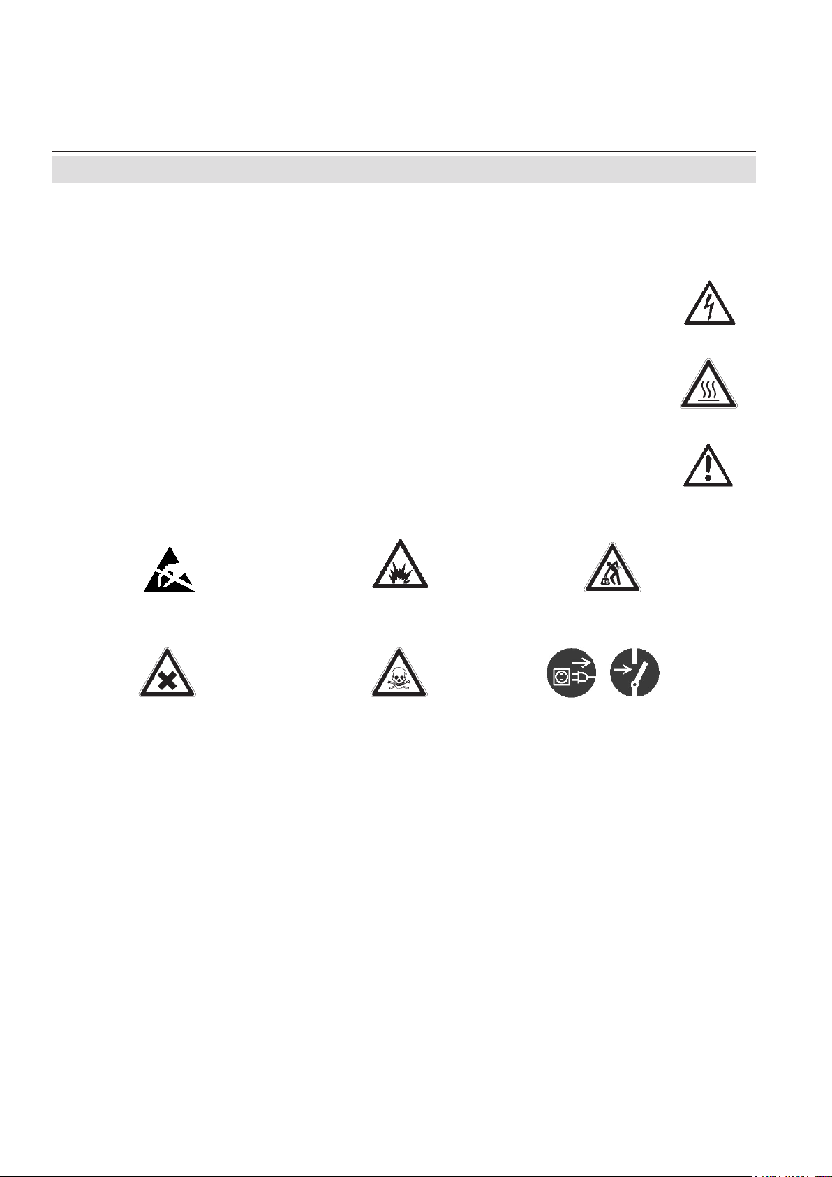
Symbols
SYMBOLS USED IN THIS MANUAL
1. Where equipment or covers are marked with the symbol to the right, hazardous voltages are likely to be present beneath. These covers should only be
removed when power is removed from the equipment — and then by trained
service personnel only.
2. Where equipment or covers are marked with the symbol to the right, there is
a danger from hot surfaces beneath. These covers should only be removed
by trained service personnel when power is removed from the equipment.
3. Where equipment or covers are marked with the symbol to the right, refer to
the Instruction Manual for instructions.
4. Further graphical symbols possibly used in this product:
Elektrostatic discharge (ESD)
Harmful (to Health)!
Explosion Hazard!
Toxic!
Heavy Instrument!
Disconnect from Mains!

Instruction Manual
HASANE-IM-ATEX
08/2007
TERMS USED IN THIS MANUAL
ATEX
Directive 94/9/EC, commonly called the
ATEX („Atmosphères Explosibles“) directive,
dealing with equipment intended to be used
in potentially explosive atmosphere.
This directive is valid for equipment to be
sold into and/or installed and operated in the
European Union (EU).
Area Classication
X-STREAM® FN
Terms
Safety Instructions
Zone 2
In Zone 2 ignitable concentrations of ammable gases are not likely to exist under
normal operating conditions.
(A guideline value [not part of a standard]:
less than 10 hours per year.)
Flammable Gas(es)
Gases and gas mixtures are assigned to be
ammable if they might become ignitable
when in a mixture with air.
Lower Explosion Limit (LEL)
Volume ratio of ammable gas in air below
which an explosive gas atmosphere will not
be formed: the mixture of gas and air lacks
sufcient fuel (gas) to burn.
Upper Explosion Limit (UEL)
Volume ratio of ammable gas in air above
which an explosive gas atmosphere will not
be formed: the mixture of gas and air is too
rich in fuel (decient in oxygen) to burn.
Emerson Process Management GmbH & Co. OHG S-3

Emerson Process Management GmbH & Co. OHGS-4
X-STREAM® FN
Instruction Manual
HASANE-IM-ATEX
08/2007
Safety Instructions
SAFETY INSTRUCTIONS
INTENDED USE STATEMENT
X-STREAM FN series gas analyzers are intended to be used as analyzers for industrial
purposes. They must not be used in medical, diagnostic or life support applications nor
as safety devices, and no independent agency certications or approvals are to be implied
as covering such applications!
SAFETY SUMMARY
If this equipment is used in a manner not specied in these instructions, protective systems may be impaired.
AUTHORIZED PERSONNEL
To avoid personal injury and loss of property, do not operate or service this instrument
before reading and understanding this instruction manual and receiving appropriate training. Save all instructions!
ADDITIONAL LITERATURE
This manual covers aspects specic for using Non-Incendive X-STREAM FN analyzers in
hazardous (classied) areas, only.
To install, start-up, operate and maintain/service the instrument in a safe manner it is
MANDATORY to read ALL additional instruction manuals shipped together with the instrument!
The following instruction manuals are available and/or referenced within this manual at
hand:
HASAxE-IM-HS X-STREAM series instruction manual
Contact your local service center or sales ofce when missing documents.
Save all instructions for future use!
Instruction Manual
HASANE-IM-ATEX
08/2007
X-STREAM® FN
Safety Instructions
EXPLOSION HAZARD BY MODIFICATION
Any addition, substitution, or replacement of components installed on or
in this device, must be certied to meet the hazardous area classication
that the device was certied to prior to any such component addition,
substitution, or replacement. In addition, the installation of such device or
devices must meet the requirements specied and dened by the hazardous
area classication of the unmodied device.
Any modications to the device not meeting these requirements, will void
the product certication(s).
Contact Emerson Process Management‘s customer service center for return
authorization.
POSSIBLE EXPLOSION HAZARD
Do not open instrument when energized.
Ensure that external circuitry is disconnected or de-energized before
opening the instrument.
Safety Instructions
Before opening the instrument ensure the waiting time, as specied on the
label at the analyzer´s enclosure, has elapsed!
Ensure that all gas connections are made as labeled and are leak free.
Improper gas connections could result in explosion and death.
POSSIBLE EXPLOSION HAZARD
The X-STREAM analyzer may utilize not only sample gas but one or more
pressurized carrier gases and/or calibration gases.
If an external owmeter is required for ow control, legislative requirements
and instructions for installation in hazardous (classied) areas must be
considered.
Emerson Process Management GmbH & Co. OHG S-5

X-STREAM® FN
The analyzer model X-STREAM FN, to which this manual relates, intended
to be wall mounted and/or outdoor installed, weighs up to approx. 26 kg
(58 lbs), depending on included options!
Use two people and/or suitable tools for transportation and lifting these
instruments!
Take care to use anchors and bolts specied to be used for the weight of
the units!
Instruction Manual
HASANE-IM-ATEX
08/2007
Safety Instructions
HEAVY INSTRUMENT
Take care the wall or stand the unit is intended to be installed at is solid and
stable to hold the units!
POSSIBLE EXPLOSION HAZARD
Flammable Gases must be intoduced in INFALLIBLE CONTAINMENTS ONLY,
to avoid leakage into internal Analyzer Housing!
Emerson Process Management GmbH & Co. OHGS-6

Instruction Manual
HASANE-IM-ATEX
08/2007
X-STREAM® FN
Table of ConTenTs
Preamble S-1
Denitions S-1
Symbols used in this manual .............................................................................................S-2
Terms used in this manual .................................................................................................S-3
Safety instructions ..............................................................................................................S-4
Chapter 1 Technical Description 1-1
1-1 Application and Principle of Operation ............................................................... 1-1
1-2 Technical Data ........................................................................................................1-2
1-2-1 Installation Site and Protection Method ........................................................... 1-2
1-2-2 General Technical Data ...................................................................................... 1-3
1-3 X-STREAM Dimensions .........................................................................................1-4
1-4 MeasurementSpecications ................................................................................1-5
1-5 Infallible Containments .........................................................................................1-5
1-6 Additional Safety Measures .................................................................................. 1-5
Table of Contents
Chapter 2 Installation 2-1
2-1 Abstract ..................................................................................................................2-1
2-2 Installation of the Instrument ................................................................................2-1
2-3 X-STREAM Dimensions .........................................................................................2-2
2-4 Connections of Gas Pipes ....................................................................................2-3
2-5 Wiring ......................................................................................................................2-4
2-5-1 Cable Gland Assembly Instruction for Shielded Cables ................................ 2-6
Chapter 3 Startup 3-1
3-1 Final Check .............................................................................................................3-1
3-2 Switching On .......................................................................................................... 3-1
Chapter 4 Maintenance 4-1
4-1 Maintenance Instructions......................................................................................4-2
4-2 Gas Paths ...............................................................................................................4-2
4-3 CheckModiedorRepairedAnalyzers .............................................................. 4-3
IHV-1Emerson Process Management GmbH & Co. OHG

Instruction Manual
X-STREAM® FN
HASANE-IM-ATEX
08/2007
Table of Contents
4-4 Enclosure Leakage Test ....................................................................................... 4-3
4-4-1 Preparation..........................................................................................................4-3
4-4-2 Run Leakage Test ..............................................................................................4-4
4-4-3 Startup after Test Procedure ............................................................................. 4-4
4-5 Replacement of Components ............................................................................... 4-5
Appendix A-1
A-1 EC Declaration of Conformity ...............................................................................A-2
A-2 Manufacturer‘s Declaration ..................................................................................A-3
A-3 Certicate ...............................................................................................................A-4
A-4 Block diagram ........................................................................................................A-5
A-5 Assignment of Plugs and Terminals ....................................................................A-6
Index of fIgures
Fig. 1-1: X-STREAM FN - Dimensions ..............................................................................................................1-4
Fig. 2-1: X-STREAM FN - Dimensions ..............................................................................................................2-2
Fig. 2-2: Marking of the gas ttings (example) ...............................................................................................2-3
Fig. 2-3: Terminal block X1 - Analog outputs .................................................................................................2-8
Fig. 2-4: Terminal block X2 - Modbus interface ..............................................................................................2-9
Fig. 2-5: X-STREAM FN - Modbus over ethernet connector ........................................................................2-10
Fig. 2-6: Relay status signals ......................................................................................................................... 2-11
Fig. 2-7: Terminal block X3 - Relay Status Terminals ..................................................................................2-11
Fig. 2-8: Terminal block X4 - Digital Inputs & Outputs .................................................................................2-12
Fig. 2-9: Power terminals ................................................................................................................................2-13
Fig. 3-1: Sealing Plug for Cable Connections .................................................................................................3-1
Fig. 3-2: Hexagon Socket Screw used as Sealing Plug .................................................................................3-1
Fig. 4-1: Assembly for check routines .............................................................................................................4-4
Fig. A-1: Terminals strip 1 ................................................................................................................................ A-6
Fig. A-2: Terminals strip 2 ................................................................................................................................ A-6
Fig. A-3: Power terminals ................................................................................................................................A-6
Fig. A-4: Ethernet connector for Modbus .......................................................................................................A-6
IHV-2 Emerson Process Management GmbH & Co. OHG

Instruction Manual
HASANE-IM-ATEX
08/2007
Chapter 1
Technical Description
1-1 Application and Principle of Operation
X-STREAM® FNX-STREAM
The Gas Analyzer model X-STREAM FN has
been developed to enable the measurement
of gas components in hazardous areas (Ex
zones):
X-STREAM FN is assembeled with selected
components (method of protection: „Non- incendive“ Ex n) to be installed and operated in
hazardous (classied) area of ex zone 2.
X-STREAM FN Analyzers which are certied
according to EN 60079-15, protection method
Ex n „Non-Incendive“, do not include components by design which may create arcs,
sparks or hot spots under normal operation
conditions. That is why they cannot ignite
an explosive atmosphere being eventually
present.
The advantage of the Non-Incendive protection type versus other protection methods is
that no other means need to be provided such
as purge gas for pressurized systems.
The used method of protection is suitable for
Zone 2 applications only. According to this
ammable/explosive gases are not allowed or
just for a short while in the ambient of these
components.
This is especially true for the measurement
of ammable gases:
Measuring ammables gases with standard
tubings (containments) would enable those
gases to pass off into the housing in case of
leakages. Together with the air being present
an explosive mixture would be built. As a
result of the tight enclosure and the missing
exchange with the surrounding atmosphere
the explosive mixture would be available for
a long time. The categorization of the internal
compartment of the X-STREAM FN analyzer would be no more according to zone 2
but zone 0 requiring special protection methods!
Nevertheless Emerson Process Management has designed infallible containments to
enable the measurement of ammable gases
in X-STREAM FN Analyzers:
These are gas paths designed as „technically
tight“ due to the construction ( 1-5, Page
1-5). Using those infallible containments in
a proper way enables the use to avoid the
leakage of ammable gases into the analyzer
and the formation of explosive atmosphere.
1 Technical Description
EXPLOSION DANGER MEASURING FLAMMABLE GASES
Flammable Gases must be introcuced into INFALLIBLE CONTAINMENTS
ONLY thus avoiding internal leakages!
Such Containments are available on request.
Emerson Process Management GmbH & Co. OHG 1-1
Instruction Manual
HASANE-IM-ATEX
08/2007
X-STREAM® FNX-STREAM
®
FN
Instruction manual
HASANE-IM-ATEX
08/2007
1-2 Technical Data
1-2 Technical Data 1-2-1 Installation Site and Protection Method
Permissible ambient temperature -20 °C (-4 °F) to +50 °C (122 °F), other
on request
Permissible storage temperature -20 °C (68 °F) to +70 °C (158 °F)
Permissible humidity (non-condensing) < 90 % r. F. at +20 °C (68 °F)
< 70 % r. F. at +40 °C (104 °F)
Pollution degree 2
Installation category I I
Altitude 0 to 2000 m (6560 ft.) Höhe über N.N.
Ambient atmosphere The Analyzer may not be
used in corro-
sive atmosphere
Protection concept:
Wall-mount eld housing for outdoor installa-
tion with protection method Ex n
Hazardous zone: Zone 2, Gas
Underlying standard:
IEC 60079-0:2004 (4th Edition)
DIN EN 60079-0:2004
IEC 60079-15:2005 (3
rd
Edition)
DIN EN 60079-15:2005
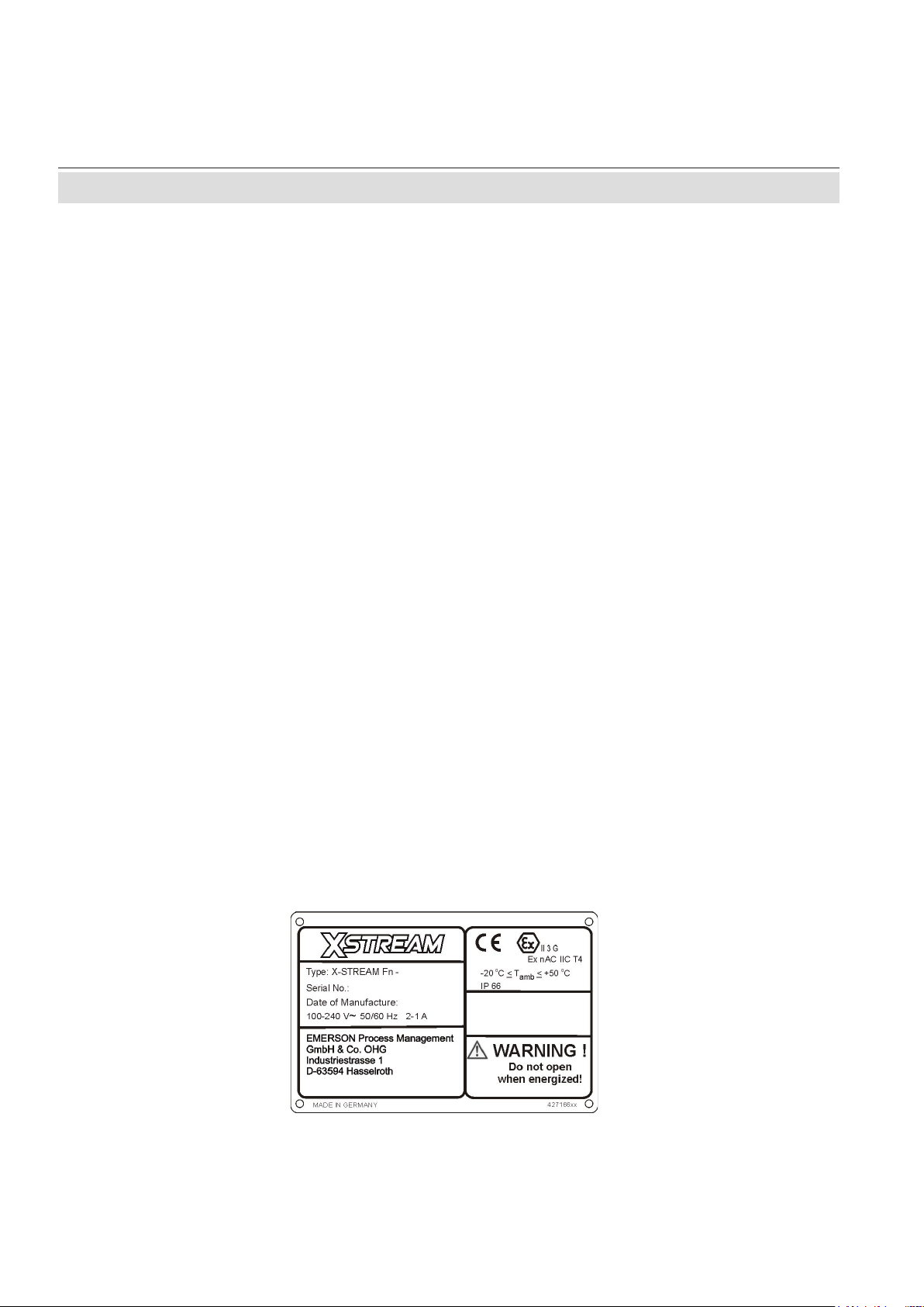
Classication:
ATEX Group II, Category 3, Gas,
Ex nAC IIC T4
Temperature class: T4
A test sample was approved by an independant test institute according to Guideline (Directive)
94/9/EG („ATEX“) and fullls the corresponding standard.
Identication Mark (Labeling)
Emerson Process Management GmbH & Co. OHG 1-2

Instruction Manual
HASANE-IM-ATEX
08/2007
X-STREAM® FNX-STREAM
Instruction Manual
HASANE-IM-ATEX
08/2007
1-2 Technical data
1-2-2 General Technical Data
For further technical data consult X-STREAM general instruction manual.
Voltage supply
Rated input voltage 100 - 240 V 50/60 Hz,
Wide range input
Power supply voltage uctation must
not exceed
voltage
Input voltage range 85 - 264 V , 47 - 63 Hz
!
X-STREAM® FNX-STREAM
+/- 10 % of the nominal
Rated input current
standard 0,75 - 0,35 A max.
with thermostatically controlled physics 2 - 1 A max.
Housing
Weight: up to 26 kg
(depending on analyzer conguration)
Protection class: IP 66 (EN 60529) / NEMA 4X
for outdoor installation analyzer must be
protected against direct sun
Gas ttings: Number: max. 8
Specication: 6/4 mm or 1/4“, stainless
steel, other on request
General Certications (Compliances)
Electrical safety
Europe CE, based on EN 61010-1
Elektromagnetic compatibility
Europe CE, based upon EN 61326
other NAMUR
1 Technical Description
Emerson Process Management GmbH & Co. OHG 1-3
Instruction Manual
HASANE-IM-ATEX
08/2007
X-STREAM® FNX-STREAM
®
FN
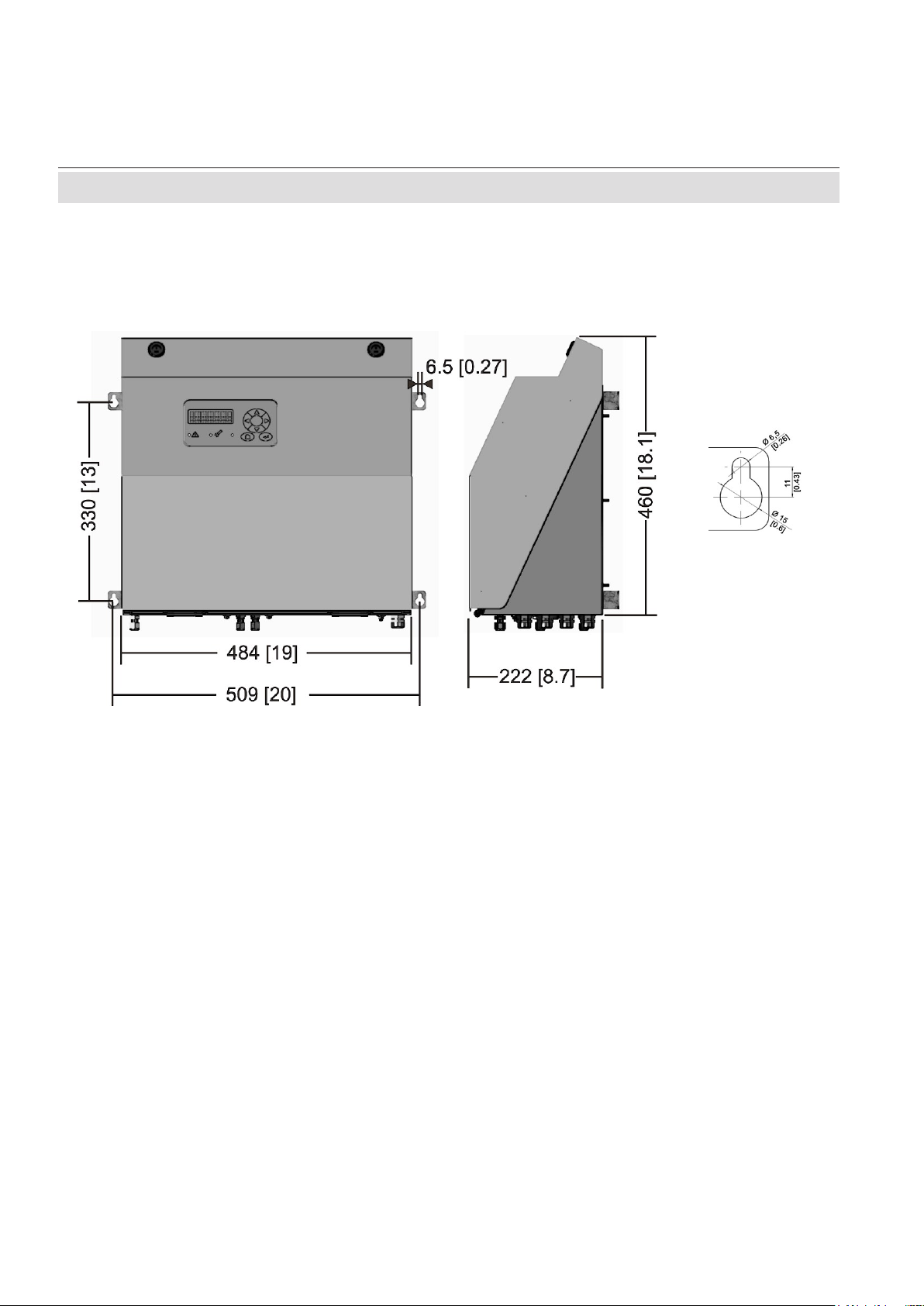
1-3 X-STREAM Dimensions
1-3 X-STREAM Dimensions
Instruction manual
HASANE-IM-ATEX
Eyebolt detail
08/2007
approx. mm [inch]
Fig. 1-1: X-STREAM FN - Dimensions
Emerson Process Management GmbH & Co. OHG 1-4
Loading...