

Manual: X-STREAM X1 Flameproof Addendum for Hazardous Area Applications-3rd Ed. | Rosemount
Table of contents
 Loading...
Rosemount Manual: X-STREAM X1 Flameproof Addendum for Hazardous Area Applications-3rd Ed. | Rosemount Manuals & Guides

Instruction Manual
HASADE-IM-Ex
07/2007
Flameproof Gas Analyzer
Instruction Manual Addendum for
Hazardous Area Applications
www.EmersonProcess.com

ESSENTIAL INSTRUCTIONS
READ THIS PAGE BEFORE PROCEEDING!
Emerson Process Management (Rosemount Analytical) designs, manufactures and
tests its products to meet many national and international standards. Because these
instruments are sophisticated technical products, you MUST properly install, use, and
maintain them to ensure they continue to operate within their normal speci.cations.
The following instructions MUST be adhered to and integrated into your safety program
when installing, using and maintaining Emerson Process Management (Rosemount
Analytical) products. Failure to follow the proper instructions may cause any one of the
following situations to occur: Loss of life; personal injury; property damage; damage to
this instrument; and warranty invalidation.
• Read all instructions prior to installing, operating, and servicing the product.
• If you do not understand any of the instructions, contact your Emerson Process
Management (Rosemount Analytical) representative for clarication.
• Follow all warnings, cautions, and instructions marked on and supplied with the
product.
• Inform and educate your personnel in the proper installation, operation, and
maintenance of the product.
• Install your equipment as speci.ed in the Installation Instructions of the
appropriate Instruction Manual and per applicable local and national codes.
Connect all products to the proper electrical and pressure sources.
• To ensure proper performance, use qualied personnel to install, operate, update,
program, and maintain the product.
• When replacement parts are required, ensure that qualied people use replacement
parts specied by Emerson Process Management (Rosemount Analytical).
Unauthorized parts and procedures can affect the product’s performance, place the
safe operation of your process at risk, and VOID YOUR WARRANTY. Look-alike
substitutions may result in re, electrical hazards, or improper operation.
• Ensure that all equipment doors are closed and protective covers are in place,
except when maintenance is being performed by qualied persons, to prevent
electrical shock and personal injury.
The information contained in this document is subject to change without notice.
3rd edition 2007-07
2nd edition 2007-04
1st edition 2006-07
Emerson Process Management GmbH & Co. OHG
Industriestrasse 1
D-63594 Hasselroth
Germany
T +49 (0) 6055 884-0
F +49 (0) 6055 884-209
Internet: www.EmersonProcess.com

Instruction Manual
HASDE-IM-Ex
04/2007
X-STREAM FD
PREAMBLE
This instruction manual provides information about installing, operating and maintaining/
servicing X-STREAM series gas analyzers in hazardous (classied) areas and shall be read
in conjunction with the standard analyzer instruction manual only!
This instruction manual covers several X-STREAM series analyzer variations and therefore
may describe congurations and/or options not part of your specic analyzer.
DEFINITIONS
The following denitions apply to WARNINGS, CAUTIONS and NOTES found throughout
this publication.
Highlights an operation or maintenance procedure, practice, condition,
statement, etc.
If not strictly observed, could result in injury, death, or long-term health
hazards of personnel.
Highlights an operation or maintenance procedure, practice, condition,
statement, etc.
Safety Instructions
If not strictly observed, could result in damage to or destruction of equipment,
or loss of effectiveness.
NOTE
Highlights an essential operating procedure, condition or statement.
Emerson Process Management GmbH & Co. OHG S-1

Instruction Manual
HASDE-IM-Ex
04/2007
Emerson Process Management GmbH & Co. OHGS-2
X-STREAM FD
Symbols
SYMBOLS USED IN THIS MANUAL
1. Where equipment or covers are marked with the symbol to the right, hazardous voltages are likely to be present beneath. These covers should only be
removed when power is removed from the equipment — and then by trained
service personnel only.
2. Where equipment or covers are marked with the symbol to the right, there is a
danger from hot surfaces beneath. These covers should only be removed by
trained service personnel when power is removed from the equipment. Certain
surfaces may remain hot to the touch.
3. Where equipment or covers are marked with the symbol to the right, refer to
the Instruction Manual for instructions.
4. Further graphical symbols possibly used in this product:
Elektrostatic discharge (ESD)
Harmful (to Health)!
Explosion Hazard!
Toxic!
Heavy Instrument!
Disconnect from Power!

Instruction Manual
HASDE-IM-Ex
04/2007
TERMS USED IN THIS MANUAL
ATEX
Directive 94/9/EC, commonly called the
ATEX („Atmosphères Explosibles“) directive,
dealing with equipment intended to be used
in potentially explosive atmospheres.
This directive is valid for equipment to be
sold into and/or installed and operated in the
European Union (EU).
Area Classication
X-STREAM FD
Terms
Safety Instructions
Zone 1
Where ignitable concentrations of ammable
gases can exist some of the time under normal operating conditions.
(A guideline value [not part of a standard ] is
10 to 1.000 hours per year.)
Flammable Gas(es)
Gases and gas mixtures are assigned to be
ammable if they might become ignitable
when in a mixture with air.
Lower Explosion Limit (LEL)
Volume ratio of ammable gas in air below
which an explosive gas atmosphere will not
be formed: the mixture of gas and air lacks
sufcient fuel (gas) to burn.
Zone 2
Where ignitable concentrations of ammable
gases are not likely to exist under normal
operating conditions.
(A guideline value [not part of a standard ] is
less than 10 hours per year.)
Upper Explosion Limit (UEL)
Volume ratio of ammable gas in air above
which an explosive gas atmosphere will not
be formed: the mixture of gas and air is too
rich in fuel (decient in oxygen) to burn.
Emerson Process Management GmbH & Co. OHG S-3

Instruction Manual
HASDE-IM-Ex
04/2007
Emerson Process Management GmbH & Co. OHGS-4
X-STREAM FD
Safety Instructions
SAFETY INSTRUCTIONS
INTENDED USE STATEMENT
X-Stream series gas analyzers are intended to be used as analyzers for industrial purposes. They must not be used in medical, diagnostic or life support applications nor as
safety devices, and no independent agency certications or approvals are to be implied
as covering such applications!
SAFETY SUMMARY
If this equipment is used in a manner not specied in these instructions, protective systems may be impaired.
AUTHORIZED PERSONNEL
To avoid explosions, loss of life, personal injury and damage to this equipment and on-site
property, do not operate or service this instrument before reading and understanding this
instruction manual and receiving appropriate training.
ADDITIONAL LITERATURE
This manual covers aspects specic for using ameproof X-STREAM FD analyzers in
hazardous (classied) areas, only.
To install, start-up, operate and maintain/service the instrument in a safe manner it is
MANDATORY to read all additional instruction manuals shipped together with the instrument!
The following instruction manuals are available and/or referenced within this manual at
hand:
HASAxE-IM-HS X-STREAM series instruction manual
HASFAE-IM-H Flame arrestors series instruction manual
The original manufacturer´s cable gland or conduit instruction manual, depending on
what is used.
Contact your local service center or sales ofce when missing documents.
Save all instructions for future use!

Instruction Manual
HASDE-IM-Ex
04/2007
X-STREAM FD
Safety Instructions
EXPLOSION HAZARD BY MODIFICATION
Any addition, substitution, or replacement of components installed on or
in this device, must be certied to meet the hazardous area classication
that the device was certied to prior to any such component addition,
substitution, or replacement. In addition, the installation of such device or
devices must meet the requirements specied and dened by the hazardous
area classication of the unmodied device.
Any modications to the device not meeting these requirements, will void
the product certication(s).
Contact Emerson Process Management‘s customer service center for return
authorization.
POSSIBLE EXPLOSION HAZARD
Do not open instrument when energized.
Ensure that external circuitry is disconnected or de-energized before
opening the instrument.
Safety Instructions
Ensure that all gas connections are made as labeled and are leak free.
Improper gas connections could result in explosion and death.
POSSIBLE EXPLOSION HAZARD
The X-STREAM analyzer may utilize not only sample gas but one or more
pressurized carrier gases and/or calibration gases.
If an external owmeter is required for ow control, legislative requirements
and instructions for installation in hazardous (classied) areas must be
considered.
Emerson Process Management GmbH & Co. OHG S-5

Instruction Manual
HASDE-IM-Ex
04/2007
Emerson Process Management GmbH & Co. OHGS-6
X-STREAM FD
The analyzer model X-STREAM FD, to which this manual relates, intended
to be wall mounted and/or outdoor installed, weighs up to approx. 63 kg
(139 lbs), depending on included options!
Use two people and/or suitable tools for transportation and lifting these
instruments!
Take care to use anchors and bolts specied to be used for the weight of
the units!
Safety Instructions
HEAVY INSTRUMENT
Take care the wall or stand the unit is intended to be installed at is solid and
stable to hold the units!
HOW TO STAY IN COMPLIANCE WITH THE
EUROPEAN DIRECTIVE 94/9/EC ("ATEX") WHEN PERFORMING GAS
ANALYSIS WITHIN A FLAMEPROOF ENCLOSURE.
Special conditions apply to using a ameproof enclosure analyzer under the scope of the
"European Directive for Equipment used in Explosive Atmosphere" (Directive 94/9/EC;
ATEX). To stay compliant to the directive please consider the following clarication sheet
released by the European ATEX Notied Body Group (see next page):

Instruction Manual
HASDE-IM-Ex
04/2007
X-STREAM FD
Safety Instructions
Safety Instructions
Emerson Process Management GmbH & Co. OHG S-7

X-STREAM FD
Instruction Manual
HASDE-IM-Ex
04/2007
Emerson Process Management GmbH & Co. OHGS-8

Instruction Manual
HASDE-IM-Ex
04/2007
X-STREAM FD
Table of ConTenTs
Preamble S-1
Denitions S-1
Symbols used in this manual .............................................................................................S-2
Terms used in this manual .................................................................................................S-3
Safety instructions ..............................................................................................................S-4
Chapter 1 Technical Description 1-1
1-1 Overview ................................................................................................................. 1-1
1-2 Design Features ..................................................................................................... 1-1
1-3 Protective Measures in Detail ............................................................................... 1-1
1-4 Explosion Protection Compliances......................................................................1-3
1-5 Technical Data ........................................................................................................1-4
Table of Contents
Chapter 2 Installation 2-1
2-1 Installing the Analyzer ...........................................................................................2-2
2-2 Connecting Gas Lines ........................................................................................... 2-3
2-3 Electrical Installation ............................................................................................. 2-5
Chapter 3 Startup 3-1
Chapter 4 Service and Maintenance 4-1
4-1 Verications and Tests after Service or Maintenance ........................................4-3
4-1-1 Routine Tests ......................................................................................................4-3
4-1-1-1 Visual Inspection ............................................................................................4-3
4-1-1-2 Tests on Flame Arrestors .............................................................................. 4-3
4-2 Replacement of Parts ............................................................................................4-4
Appendix A-1
A-1 EC Declaration of Conformity ...............................................................................A-2
A-2 ATEX EC Type Examination Certicate ...............................................................A-3
A-3 Cable gland ADL 1F installation instruction ........................................................A-7
A-4 Block diagram X-STREAM FD ...............................................................................A-8
A-5 Assignment of Terminals and Socket .................................................................A-9
TOC-1Emerson Process Management GmbH & Co. OHG

Instruction Manual
X-STREAM FD
HASDE-IM-Ex
04/2007
Table of Contents
Table of figures
Fig. 1-1: X-STREAM FD .....................................................................................................................................1-1
Fig. 1-2: X-STREAM FD, bottom view ..............................................................................................................1-2
Fig. 1-3: X-STREAM FD - dimensions .............................................................................................................1-4
Fig. 1-4: X-STREAM FD - power terminals / fuse holders ..............................................................................1-7
Fig. 1-5: X-STREAM FD - signals terminals ....................................................................................................1-8
Fig. 2-1: X-STREAM FD dimensions ................................................................................................................2-2
Fig. 2-2: Flame arrestor installed into instrument enclosure ........................................................................2-3
Fig. 2-3: Flame arrestor elements, considering as example FA 01 ...............................................................2-3
Fig. 2-4: X-STREAM FD - allocation of terminals ..........................................................................................2-10
Fig. 2-5: X-STREAM FD - Analog output terminals .......................................................................................2-12
Fig. 2-6: X-STREAM FD - Modbus interface terminals .................................................................................2-13
Fig. 2-7: X-STREAM F - Modbus over ethernet connector ...........................................................................2-14
Fig. 2-9: X-STREAM FD - Relay Status Terminals ........................................................................................2-15
Fig. 2-8: Relay status signals, block diagram ..............................................................................................2-15
Fig. 2-10: Digital Inputs & Outputs Terminals ...............................................................................................2-16
Fig. 2-11: Power terminals ..............................................................................................................................2-17
Fig. 2-12: Equipotential bonding conductor terminal ..................................................................................2-18
Fig. A-1: Terminals strip 1 ................................................................................................................................A-9
Fig. A-2: Terminals strip 2 ................................................................................................................................A-9
Fig. A-3: Power terminals ................................................................................................................................A-9
Fig. A-4: Ethernet connector for Modbus ....................................................................................................... A-9
TOC-2 Emerson Process Management GmbH & Co. OHG

Instruction Manual
HASADE-IM-EX
07/2007
X-STREAM FD
Chapter 1
Technical Description
1-1 Overview
The new X-STREAM FD gas analyzer is designed to be used in hazardous areas. Its ameproof enclosure can be installed at Zone 1
locations without the need of any additional
protective measures, e.g. purge gas supply.
1-2 Design Features
Packaged into a cast aluminum enclosure, the
X-STREAM FD gas analyzer provides all the
measurement options available for general
purpose instruments, but for installation at locations where explosive atmosphere might be
present frequently and classied as Zone 1.
The basic concept used is to protect the surrounding atmosphere from being ignited if an
internal failure results in high temperatures,
ames or even an explosion.
To provide adequate explosion protection
the X-STREAM FD analyzer features several
protection methods:
•
The cast aluminum enclosure is designed to
• withstand an internal explosion,
• extinguish the ames resulting from an
internal explosion (thus preventing a
sur-rounding explosive atmoshere from
being ignited).
• Flame arrestors avoide ame transmission
from the gas paths into the surrounding
atmosphere.
• Approved cable glands (option: conduits)
protect the cable inlets and outlets.
1-3 Protective Measures in Detail
The cast aluminum enclosure consists of
two parts: base and cover, connected by
hinges.
The area where the two parts are in contact
is designed to work as a ange, quenching
ames entering the small path between them.
When operated, the analyzer enclosure has to
be closed and secured by 20 screws evenly
arranged all over the ange.
6
3
1: Enclosure base
2: Screws
3: Enclosure cover
4: Flange
5: Eyebolts for lifting
6: Eyebolts for installation
7: Hinges
Fig. 1-1: X-STREAM FD
Emerson Process Management GmbH & Co. OHG 1-1
2
7
4
5
1
1 Technical Description
X-STREAM FD
Emerson Process Management GmbH & Co. OHG1-2
Instruction Manual
HASADE-IM-EX
07/2007
1-3 Protective Measures in Detail
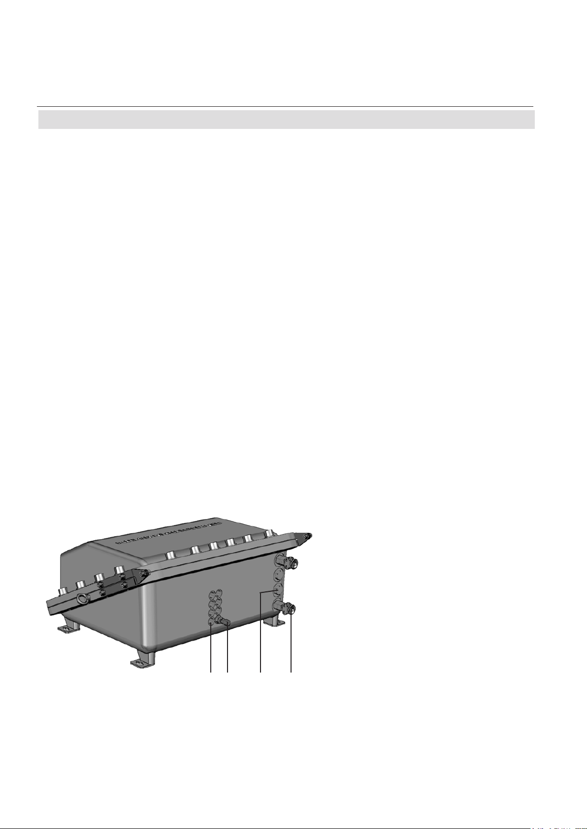
The only openings penetrating the enclosure
are threads, to be used for gas and cable inand outlets:
Depending on the measurement application
the instrument provides up to 8 gas in- and
outlets, each protected by an approved ame
arrestor. These arrestors are installed into
threads at the bottom side of the enclosure
base. Two tting sizes are available for external connection of gas pipes with 3.18 mm
(1/8“) or 6.35 mm (1/4“) outer diameter (OD).
Optionally a clamping ring for 6 mm OD may
be used, replacing the 6.35 mm version.
Cables are fed into the enclosure utilizing up
to 4 cable glands, located at the enclosure`s
bottom right side. The approved glands accept
3 different internal elastomeric sealing rings
with different internal diameters, supporting
a wide range of cables.
For installation in North-America cable glands
are replaced by a combination of conduits and
metric-to-NPT thread adapters.
All threads provide a ame path of a length
ensuring that possibly entering ames are
extin-guished before reaching the external
atmos-phere.
Unused threads must be closed with plugs
when the instrument is operated to ensure
explosion protection.
Note!
See the X-STREAM series instruction manual
for more information about common X-STREAM
series gas analyzers features and special
features of the X-STREAM FD.
1: Plugged when not used
2: Gas tting (part of ame arrestor)
3: Plug
4: Cable gland (or conduits)
1 2 3 4
Fig. 1-2: X-STREAM FD, bottom view

Instruction Manual
HASADE-IM-EX
07/2007
X-STREAM FD
1-4 Compliances
1-4 Explosion Protection Compliances
This product is available in two different variations, separately certied by agencies for the use
in hazardous (classied) areas:
The one version, to be equipped with metric-to-NPT adapters and conduits (these components
are not part of the instrument certication), is certied by the Canadian Standards Association,
an „OSHA Nationally Recognized Testing Labor tory“ (NRTL), for Canada and USA and conforms
to the provisions of CAN/CSA-E60079-0:02 (R2006), CAN/CSA-E60079-1:02 (R2006), ANSI/ISA-
12.00.01-2002 (IEC 60079-0 Mod), ANSI/ISA-12.22.01-2002 (IEC 60079-1 Mod).
The second variation, to be equipped with cable glands, is certied by Fyzikálně technický
zkušební ústav, s.p (FTZÚ), an European Notied Body under the Directive 94/9/EC („ATEX“)
and conforms to the provisions of EN 60079-0 and EN 60079-1. See appendix for a copy of the
CE type examination certicate.
Depending on the variation, the following certication markings apply to the product:
Class I, Zone 1, AEx d IIB + H2 T3
USA
Canada Class I, Zone 1, Ex d IIB + H2 T3
European Union (EU) ATEX, category 2, Zone 1, Ex d IIB + H2 T4
EC ATEX Type Examination Certicate: FTZU 06 ATEX 0186.
Conforms with the provisions of the „Equipment intended for use in Potentially Explosive Atmospheres (ATEX)“ Directive 94/9/EC, EMC Directive 89/336/EEC and CE Directive 93/68/EEC.
1 Technical Description
Emerson Process Management GmbH & Co. OHG 1-3

X-STREAM FD
Emerson Process Management GmbH & Co. OHG1-4
Instruction Manual
HASADE-IM-EX
07/2007
1-5 Technical Data
1-5 Technical Data
Flame arrestors with gas ttings
(enclosure threads: M18 x 1.5)
(enclosure threads; M20 x 1.5)
Cable inlets
Eyebolt detail
approx. in mm [inches]
Fig. 1-3: X-STREAM FD - dimensions
Housing
Permissible ambient temperature range -22 F to 122 F ( -30 °C to +50 °C)
Weight: approx. up to 139 lbs (63 kg)
(depending on analyzer conguration)
Protection class: IP 66 (EN 60529) / NEMA 4X
for outdoor installation
Analyzer must not be exposed to direct
sun light
Gas ttings: quantity: max. 8
specication: ame arrestors with ttings
6/4 mm or 1/4“, stainless steel

Instruction Manual
HASADE-IM-EX
07/2007
X-STREAM FD
1-5 Technical Data
Site of installation
Humidity (non condensing) < 90 % r. h. at 68 F (+20 °C)
< 70 % r. h. at 104 F (+40 °C)
Pollution degree 2
Installation category I I
Altitude 0 to 6560 ft (2000 m) above sea level
Sourrounding atmosphere Analyzers must not be operated in
corrosive atmosphere.
General Purpose Compliances
Electrical safety CAN / USA CSA-C/US, based on
CAN/CSA-C22.2 No. 61010-1-04 /
UL 61010-1, 2nd Edition
Europe CE, based on EN 61010-1
Electromagnetic compatibility
Europe CE, based on EN 61326
other NAMUR
Power supply
Rated input voltageated input voltage
100 - 240 V 50/60 Hz, wide range input
Power supply voltage uctuations are
not to exceed +/- 10 % of the nominal
supply voltage!
Input voltage range 85 - 264 V , 47 - 63 Hz
Rated input current
standard 0,75 - 0,35 A max.
with thermostated physics 2 - 1 A max.
1 Technical Description
Emerson Process Management GmbH & Co. OHG 1-5

X-STREAM FD
Emerson Process Management GmbH & Co. OHG1-6
Instruction Manual
HASADE-IM-EX
07/2007
1-5 Technical Data
Interfaces, signal inputs / outputs
2 analog outputs channel 4 (0) - 20 mA (RB < 500 Ω)
(optically isolated; congurable by keypad
start and end concentration user congurable)
Modbus interface RS 485 (2- or 4-wire)
optional:
RS 232 with or without optical isolation
Ethernet (RJ45 socket)
3 relay outputs (option „status signals“) “Failure”
according NAMUR NE 107 “Maintenance required / Off specication“
“Function check”
dry contacts, max. 30 V; 1 A; 30 W resistive
Digital Inputs and Outputs (option)
7 digital inputs zero calibration ch1 & ch2,
(common ground) span calibration ch1,
span calibration ch2,
open valve V4
open valve V1
open valve V2
open sample gas valve V3 /
switch off sample pump
max. 30 V, internally limited to 2.3 mA
H level: min. 4 V; L level: max. 3 V
8 digital outputs 2 thresholds per channel,
(optically isolated, common ground) sample gas valve,
zero gas valve V4,
span gas valve V1,
span gas valve V2
“Open Collector”, max. 30 V / 30 mA
Gas parameters
X-STREAM Instruction Manual, chapter 3 Measuring Principles
Loading...