

Manual: World Class 3000 O2 Analyzer DR Direct Replacement Probe-Rev 3.3 | Rosemount
Table of contents
 Loading...
Rosemount Manual: World Class 3000 O2 Analyzer DR Direct Replacement Probe-Rev 3.3 | Rosemount Manuals & Guides
Instruction Manual
IB-106-300DR Rev. 3.3
February 2000
World Class 3000
Oxygen Analyzer Direct
Replacement Probe for
use with Existing Signal
Conditioning Electronics
http://www.processanalytic.com

ESSENTIAL INSTRUCTIONS
READ THIS PAGE BEFORE PROCEEDING!
Rosemount Analytical designs, manufactures and tests its products to meet many national and
international standards. Because these instruments are sophisticated technical products, you
MUST properly install, use, and maintain them to ensure they continue to operate within their
normal specifications. The following instructions MUST be adhered to and integrated into your
safety program when installing, using, and maintaining Rosemount Analytical products. Failure to
follow the proper instructions may cause any one of the following situations to occur: Loss of life;
personal injury; property damage; damage to this instrument; and warranty invalidation.
• Read all instructions prior to installing, operating, and servicing the product.
• If you do not understand any of the instructions, contact your Rosemount Analytical repre-
sentative for clarification.
• Follow all warnings, cautions, and instructions marked on and supplied with the product.
• Inform and educate your personnel in the proper installation, operation, and mainte-
nance of the product.
• Install your equipment as specified in the Installation Instructions of the appropriate In-
struction Manual and per applicable local and national codes. Connect all products to the
proper electrical and pressure sources.
• To ensure proper performance, use qualified personnel to install, operate, update, program,
and maintain the product.
• When replacement parts are required, ensure that qualified people use replacement parts
specified by Rosemount. Unauthorized parts and procedures can affect the product’s performance, place the safe operation of your process at risk, and VOID YOUR WARRANTY.
Look-alike substitutions may result in fire, electrical hazards, or improper operation.
• Ensure that all equipment doors are closed and protective covers are in place, except
when maintenance is being performed by qualified persons, to prevent electrical shock
and personal injury.
The information contained in this document is subject to change without notice.
Emerson Process Management
Rosemount Analytical Inc.
Process Analytic Division
1201 N. Main St.
Orrville, OH 44667-0901
T (330) 682-9010
F (330) 684-4434
e-mail: gas.csc@EmersonProcess.com
http://www.processanalytic.com

HIGHLIGHTS OF CHANGES
Effective June, 1996 Rev. 3
Page Summary
--- General. Updated text and illustrations to reflect probe design
changes.
Page 1-15 Added “Extended temperature by-pass arrangements” to Figure 1-15,
sheet 3 of 3.
Effective December, 1996 Rev. 3.1
Page Summary
Page P-2 Added "Safety instructions for the wiring and installation of this
apparatus".
Page 1-4 Corrected Figure 1-3 item listing.
Page 2-1 Added one WARNING to read new safety instructions and another
WARNING regarding protective covers and grounds.
Page 3-1 Added WARNING regarding protective covers and grounds.
Page 4-1 Added WARNING regarding protective covers and grounds.
Page 4-6 Added title block to Figure 4-6.
Page 5-1 Added WARNING regarding protective covers and grounds.
Page 7-1 Corrected cell replacement kit part numbers in Table 7-1.
Page 7-2 Corrected cell replacement kit part number in Table 7-1.
Effective May, 1997 Rev. 3.2
Page Summary
Page P-2 Added safety sheet.
Effective February, 1998 Rev. 3.3
Page Summary
Page 2-2 Figure 2-1. Changed calibration gas tube dimensions.


World Class 3000
PREFACE.........................................................................................................................P1
Definitions ......................................................................................................................... P1
Safety Instructions ........................................................................................................... P2
1-0 DESCRIPTION AND SPECIFICATIONS........................................................................ 1-1
1-1 Component Checklist ..................................................................................................... 1-1
1-2 System Overview............................................................................................................ 1-1
1-3 Physical Description ....................................................................................................... 1-3
1-4 Probe Exterior................................................................................................................. 1-5
1-5 Probe Interior .................................................................................................................. 1-7
1-6 Junction Box .................................................................................................................... 1-8
1-7 Cable Assembly...............................................................................................................1-9
1-8 Probe Options................................................................................................................. 1-9
2-0 INSTALLATION .............................................................................................................. 2-1
2-1 Locating The Oxygen Analyzer Probe.......................................................................... 2-1
2-2 Service Required .............................................................................................................2-1
2-3 Mechanical Installation ................................................................................................... 2-6
2-4 Electrical Installation ........................................................................................................ 2-7
Instruction Manual
IB-106-300DR Rev. 3.3
February 2000
TABLE OF CONTENTS
3-0 STARTUP........................................................................................................................ 3-1
3-1 Overview.......................................................................................................................... 3-1
3-2 Models 218, 225, And 132 (Analog) Electronics Setup............................................. 3-1
3-3 Model 218A Electronics Setup ..................................................................................... 3-2
3-4 Model TC200 Veritrim Electronics Setup ..................................................................... 3-3
3-5 Model 132 Digital Electronics Setup............................................................................ 3-4
3-6 The Yokogawa ZA8C And AV8C Converter Electronics Setup ................................ 3-4
4-0 MAINTENANCE AND SERVICE .................................................................................. 4-1
4-1 Overview.......................................................................................................................... 4-1
4-2 Probe Calibration ............................................................................................................. 4-1
4-3 Cell Replacement ........................................................................................................... 4-1
4-4 Optional Ceramic Diffusion Element Replacement ..................................................... 4-3
4-5 Replacement Of Contact And Thermocouple Assembly ............................................. 4-5
4-6 Replacement Of Heater, V-Strut And Backplate Assembly ..................................... 4-7
4-7 Calibration And Reference Gas Lines For High Temperature -
Corrosive Environment Operation ................................................................................... 4-9
5-0 TROUBLESHOOTING .................................................................................................... 5-1
5-1 Overview.......................................................................................................................... 5-1
5-2 Probe Troubleshooting ................................................................................................... 5-1
6-0 RETURN OF MATERIAL .............................................................................................. 6-1
7-0 REPLACEMENT PARTS ................................................................................................ 7-1
8-0 INDEX.............................................................................................................................. 8-1
Rosemount Analytical Inc. A Division of Emerson Process Management i

Instruction Manual
IB-106-300DR Rev. 3.3
February 2000
Figure 1-1. Typical System Package ....................................................................................... 1-1
Figure 1-2. Typical System Installation .................................................................................... 1-3
Figure 1-3. Oxygen Analyzer Probe - Exploded View.............................................................. 1-4
Figure 1-4. Main Probe Components ....................................................................................... 1-5
Figure 1-5. Cell and Tube Assemblies ..................................................................................... 1-5
Figure 1-6. Optional Ceramic Diffusor and Vee Deflector Assembly....................................... 1-7
Figure 1-7. Inner Probe Assembly............................................................................................ 1-8
Figure 1-8. Junction Box .......................................................................................................... 1-8
Figure 1-9. Abrasive Shield Assembly ................................................................................... 1-10
Figure 1-10. Ceramic Diffusion/Dust Seal Assembly ............................................................... 1-11
Figure 1-11. Flame Arrestor Diffusion/Dust Seal Assembly..................................................... 1-11
Figure 1-12. Ceramic Diffusion Assembly................................................................................ 1-11
Figure 1-13. Flame Arrestor Diffusion Assembly ..................................................................... 1-11
Figure 1-14. Snubber Diffusion/Dust Seal Assembly............................................................... 1-12
Figure 1-15. Bypass Probe Option (Sheet 1 of 3) .................................................................... 1-13
Figure 2-1. Probe Installation (Sheet 1 of 5) ............................................................................ 2-2
Figure 2-2. Orienting the Optional Vee Deflector ..................................................................... 2-7
Figure 2-3. Wiring the Direct Replacement Probe ................................................................... 2-8
Figure 3-1. Temperature Controller Card Calibration Points ................................................... 3-1
Figure 3-2. Main PCB (Model 218A) EPROM Replacement ................................................... 3-2
Figure 3-3. Main PCB (Model TC200) EPROM Replacement ................................................. 3-3
Figure 3-4. Main PCB (Model 132) EPROM Replacement...................................................... 3-4
Figure 3-5. DR Probe Wired to the ZA8C or A V8C Converter ................................................ 3-5
Figure 4-1. Cell Wiring Connection .......................................................................................... 4-2
Figure 4-2. Removal of Optional Ceramic Diffusor and Vee Deflector .................................... 4-3
Figure 4-3. Cell Replacement Kit ............................................................................................. 4-3
Figure 4-4. Junction Box Mechanical Connections.................................................................. 4-5
Figure 4-5. Inner Probe Replacement (Heater, V-Strut, and Backplate Assembly)................ 4-6
Figure 4-6. Heater, Strut, and Backplate Assembly (Inner Probe Assembly).......................... 4-6
Figure 4-7. Oxygen Analyzer Probe, Cross-Sectional View .................................................... 4-8
Figure 4-8. High Temperature – Corrosive Environment Kit .................................................... 4-9
World Class 3000
LIST OF ILLUSTRATIONS
LIST OF TABLES
Table 1-1. Specifications for Oxygen Analyzing Equipment
Table 5-1. Fault Finding .......................................................................................................... 5-2
Table 7-1. Replacement Parts for Probe ................................................................................ 7-1
ii Rosemount Analytical Inc. A Division of Emerson Process Management
1 2
............................................... 1-6
World Class 3000
The World Class 3000 Direct Replacement Probe can be used with any of the following
model electronics: 218, 225, 218A, ZA8C, and TC200. Read the appropriate setpoint adjustment in this manual to prevent damage to the probe.
The purpose of this manual is to provide information concerning the components, functions, installation and maintenance of this particular probe.
Some sections may describe equipment not used in your configuration. The user should
become thoroughly familiar with the operation of this module before operating it. Read
this instruction manual completely.
The following definitions apply to WARNINGS, CAUTIONS, and NOTES found throughout this
publication.
Instruction Manual
IB-106-300DR Rev. 3.3
February 2000
CAUTION
!
PREFACE
DEFINITIONS
Highlights an operation or maintenance
procedure, practice, condition, statement, etc. If not strictly observed, could
result in injury, death, or long-term
health hazards of personnel.
NOTE
Highlights an essential operating procedure,
condition, or statement.
: EARTH (GROUND) TERMINAL
: PROTECTIVE CONDUCTOR TERMINAL
: RISK OF ELECTRICAL SHOCK
: WARNING: REFER TO INSTRUCTION BULLETIN
Highlights an operation or maintenance
procedure, practice, condition, statement, etc. If not strictly observed, could
result in damage to or destruction of
equipment, or loss of effectiveness.
NOTE TO USERS
The number in the lower right corner of each illustration in this publication is a manual illustration number. It is not a part number, and is not related to the illustration in any technical
manner.
Rosemount Analytical Inc. A Division of Emerson Process Management P-1
Instruction Manual
IB-106-300DR Rev. 3.3
February 2000
FOR THE WIRING AND INSTALLATION
The following safety instructions apply specifically to all EU member states. They should
be strictly adhered to in order to assure compliance with the Low Voltage Directive. NonEU states should also comply with the following unless superseded by local or National
Standards.
1. Adequate earth connections should be made to all earthing points, internal and external,
where provided.
2. After installation or troubleshooting, all safety covers and safety grounds must be replaced.
The integrity of all earth terminals must be maintained at all times.
3. Mains supply cords should comply with the requirements of IEC227 or IEC245.
World Class 3000
IMPORTANT
SAFETY INSTRUCTIONS
OF THIS APPARATUS
4. All wiring shall be suitable for use in an ambient temperature of greater than 75°C.
5. All cable glands used should be of such internal dimensions as to provide adequate cable
anchorage.
6. To ensure safe operation of this equipment, connection to the mains supply should only be
made through a circuit breaker which will disconnect all circuits carrying conductors during a
fault situation. The circuit breaker may also include a mechanically operated isolating switch.
If not, then another means of disconnecting the equipment from the supply must be provided
and clearly marked as such. Circuit breakers or switches must comply with a recognized
standard such as IEC947. All wiring must conform with any local standards.
7. Where equipment or covers are marked with the symbol to the right, hazardous voltages are likely to be present beneath. These covers should only be
removed when power is removed from the equipment — and then only by
trained service personnel.
8. Where equipment or covers are marked with the symbol to the right, there is a
danger from hot surfaces beneath. These covers should only be removed by
trained service personnel when power is removed from the equipment. Certain surfaces may remain hot to the touch.
9. Where equipment or covers are marked with the symbol to the right, refer to
the Operator Manual for instructions.
10. All graphical symbols used in this product are from one or more of the following standards: EN61010-1, IEC417, and ISO3864.
P-2 Rosemount Analytical Inc. A Division of Emerson Process Management

World Class 3000
1
DESCRIPTION AND SPECIFICATIONS
Instruction Manual
IB-106-300DR Rev. 3.3
February 2000
SECTION 1
1-1 COMPONENT CHECKLIST
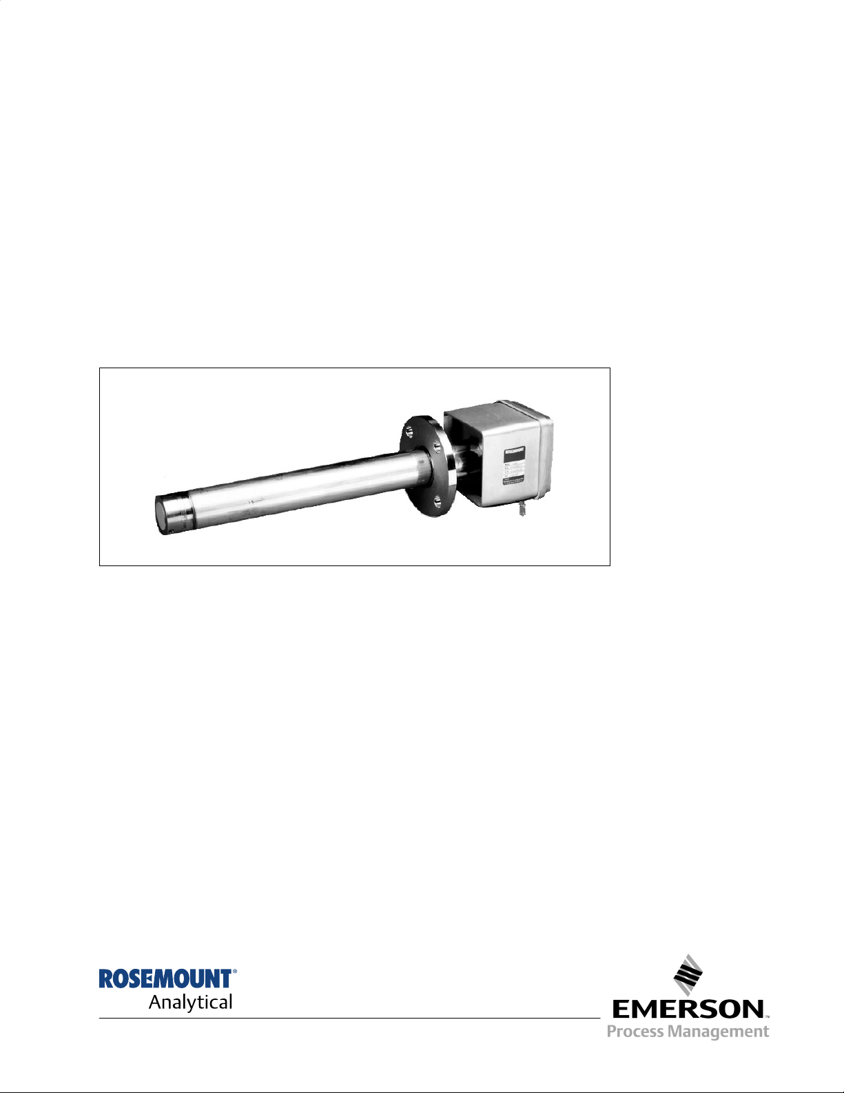
The Direct Replacement (DR) Probe package of
the World Class 3000 Oxygen Analyzer typically
includes the probe, the instruction bulletin, and
the mounting hardware. These three items are
shown in Figure 1-1. Record the Part Number,
Serial Number, and Order Number of your
system on the first page of this manual.
1-2 SYSTEM OVERVIEW
a. Scope
This Instruction Bulletin has been designed
to supply details needed to install, start up,
and troubleshoot the Rosemount World
Class 3000 Oxygen Analyzer. The Direct
Replacement Probe can be interfaced to a
number of different and earlier model
electronics packages. These electronic
packages are not covered in this manual.
For specific information concerning calibration and operation of the system, refer to
the Instruction Bulletin applicable to your
electronics package.
b. System Function
The Rosemount Oxygen Analyzer (Probe) is
designed to measure the net concentration
of oxygen in an industrial process; i.e., the
oxygen remaining after all fuels have been
oxidized. The probe is permanently positioned within an exhaust duct or stack. The
sampling system is in situ rather than
extractive.
2
1. Oxygen Analyzer Probe
2. Mounting Adapter Plate with
Mounting Hardware and
Gasket
3. Instruction Bulletin
3
1
19290001
Figure 1-1. Typical System Package
Rosemount Analytical Inc. A Division of Emerson Process Management Description and Specifications 1-1

Instruction Manual
IB-106-300DR Rev. 3.3
February 2000
World Class 3000
The equipment measures oxygen percentage by reading the voltage developed
across a heated electrochemical cell, which
consists of a small yttria-stabilized, zirconia
disc. Both sides of the disc are coated with
porous metal electrodes. When operated at
the proper temperature, the millivolt output
voltage of the sensor cell is given by the
following Nernst equation:
EMF = KT log
10(P1/P2
) + C
Where:
1. P
is the partial pressure of the oxygen
2
in the measured gas on one side of the
cell,
2. P
is the partial pressure of the oxygen
1
in the reference gas on the other side,
3. T is the absolute temperature,
4. C is the cell constant,
5. K is an arithmetic constant.
NOTE
For best results, use clean, dry,
instrument air (20.95% oxygen) as a
reference gas.
vapor. Therefore, it may be considered an
analysis on a "wet" basis. In comparison
with older methods, such as the Orsat
apparatus, which provides an analysis on a
"dry" gas basis, the "wet" analysis will, in
general, indicate a lower percentage of
oxygen. The difference will be proportional
to the water content of the sampled gas
stream.
c. System Configuration
The DR probe is similar to the Exchange
Probe (NE model) except that the DR uses
a 115 V heater like most older systems. The
DR does not require a separate power supply as does the NE. The DR probe (like the
NE) is available in five lengths. The length
of stack penetration depends on the size of
the stack or duct. The length options are
18 in., 3 ft, 6 ft, 9 ft, and 12 ft (457 mm, 0.9
m, 1.8 m, 2.7 m, and 3.7 m).
d. Features
1. Output voltage and sensitivity increase
as the oxygen concentration
decreases.
When the cell is at operating temperature,
oxygen ions will travel through the cell from
high to low oxygen partial pressures. The
resulting output voltage is about 50 mV per
decade. The voltage varies with the ratio of
oxygen partial pressures of the reference
gas over the sample gas. Thus, the output
signal increases as the sample oxygen level
decreases. This property gives the analyzer
high sensitivity at low oxygen levels.
Oxygen analyzer equipment measures net
oxygen concentration in the presence of all
the products of combustion, including water
2. In situ, non-sampling analyzer.
3. Field replaceable cell.
4. Analyzer constructed of rugged
316 LSS for all wetted parts.
5. Suitable for use in temperatures up to
1300°F (700°C).
6. The DR probe uses a 115 V heater
and does not require a separate heater
power supply.
1-2 Description and Specifications Rosemount Analytical Inc. A Division of Emerson Process Management

World Class 3000
1
e. Handling the Oxygen Analyzer
Instruction Manual
IB-106-300DR Rev. 3.3
February 2000
GASES
It is important that printed circuit
boards and integrated circuits are
handled only when adequate antistatic
precautions have been taken to prevent possible equipment damage.
The oxygen analyzer is designed for
industrial application. Treat each
component of the system with care to
avoid physical damage. The probe
contains components made from ceramics, which are susceptible to
shock when mishandled.
NOTE
Retain packaging in which the oxygen
analyzer arrived from the factory in
case any components are to be
shipped to another site. This packaging has been designed to protect the
product.
f. System Considerations
Prior to installation of your Rosemount
World Class 3000 Oxygen Analyzer, make
sure you have all of the components
necessary to make the system installation.
Ensure all components are properly
integrated to make the system functional.
STACK
CALIBRATION
INSTRUMENT
AIR SUPPLY
(REF. GAS)
GAS
PRESSURE
REGULATOR
FLOWMETER
EXISTING
ELECTRONICS
Figure 1-2. Typical System Installation
connecting test gas tanks to the oxygen
analyzer when the probe is to be calibrated.
NOTE
Ambient air is not recommended for
use as high test gas. An 8% O
balance in nitrogen is recommended
for high test gas.
DUCT
ADAPTER
OXYGEN
ANALYZER
(PROBE)
2
PLATE
VOLTAGE
19290002
LINE
Once you have verified you have all the
components, select mounting locations and
determine how each component will be
placed in terms of available power supply,
ambient temperatures, environmental considerations, convenience, and serviceability.
A typical installation is illustrated in Figure
1-2.
If test gas bottles will be hooked up permanently, an optional check valve is recommended next to the calibration fittings on
the probe head. This is to prevent breathing
of calibration gas line and subsequent flue
gas condensation and corrosion. The check
valve is in addition to the stop valve in the
test gas kit or the solenoid valve in the
multiprobe test gas sequencer units.
After selecting the probe mounting location,
provision should be made for a platform
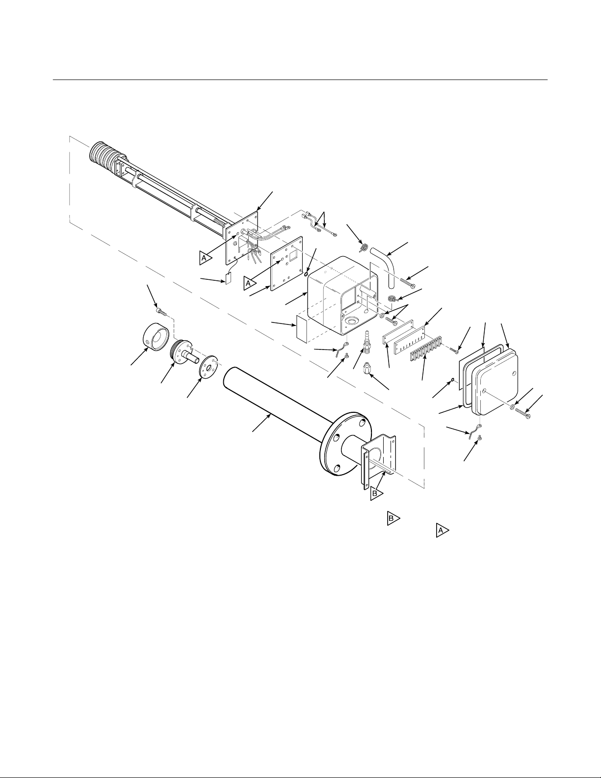
1-3 PHYSICAL DESCRIPTION
where the probe can be easily serviced.
The Oxygen Analyzer Probe, Figure 1-3 conA source of instrument air is required at the
probe for reference gas use. Since the
sists of three component groups: probe exterior,
inner probe, and junction box, Figure 1-4.
probe is equipped with an in place calibration feature, provision should be made for
Rosemount Analytical Inc. A Division of Emerson Process Management Description and Specifications 1-3
Instruction Manual
IB-106-300DR Rev. 3.3
February 2000
NOTE: NOT ALL PARTS SHOWN ARE AVAILABLE FOR
PURCHASE SEPARATELY. FOR LIST OF
AVAILABLE PARTS, SEE TABLE 7-1.
World Class 3000
1
26
20
18
23
21
19
16
14
20
12
29
10
17
11
13
15
9
28
3
2
4
30
27
25
24
11
22
10
5
6
NOTE: ITEM , CALIBRATION GAS TUBE,
FITS INTO HOLES WHEN PROBE IS
ASSEMBLED.
1. Heater, Strut, and Backplate 11. Probe Junction Box Cover 22. Gas Connection
Assembly 12. Cover Gasket 23. Seal Cap
2. Diffusion Assembly 13. Insulating Sheet 24. Label
3. Retainer Screw 14. O-Ring 25. Probe Junction Box
4. Cell and Flange 15. Terminal Block Screw 26. Ground Wires
5. Corrugated Seal 16. Terminal Block 27. Insulating Gasket
6. Probe Tube Assembly 17. Terminal Block Marker 28. Washer
7. Cover Screw 18. Terminal Block Mounting Plate 29. Screw
8. Washer 19. Probe Junction Box Screws 30. Tag
9. Cover Chain Screw 20. Hose Clamp
10. Cover Chain 21. Hose
35900002
8
7
Figure 1-3. Oxygen Analyzer Probe - Exploded View
1-4 Description and Specifications Rosemount Analytical Inc. A Division of Emerson Process Management

World Class 3000
1
PROBE
EXTERIOR
(SENSING CELL INSTALLED)
PROBE
INTERIOR
Instruction Manual
IB-106-300DR Rev. 3.3
February 2000
PROBE
JUNCTION
BOX
Figure 1-4. Main Probe Components
1-4 PROBE EXTERIOR
Primary probe exterior components include a
flange-mounted zirconium oxide cell, mounted
on a tube assembly and protected by a snubber
diffusion assembly.
a. Cell and Flange Assembly
The primary component in the cell and
flange assembly, Figure 1-5, is a
yttria-stabilized zirconium oxide cell. The
cell creates an electrical signal when the
oxygen level on one side is out of balance
with the oxygen level on the other side. This
signal is proportional to the difference in
oxygen levels.
b. Probe Tube Assembly
21240006
The tube assembly includes a flange which
mates with a stack-mounted flange (shown
attached to the probe flange in Figure 1-4).
Studs on the stack flange make installation
easy. There is also a tube to carry calibration gas from the junction box to the
process side of the cell during calibration.
PROBE TUBE
CORRUGATED
SEAL
CELL AND
FLANGE
ASSEMBLY
Four screws secure the cell and flange assembly, Figure 1-5, to the probe tube assembly. When in place, the cell is inside the
tube.
21240007
Figure 1-5. Cell and Tube Assemblies
Rosemount Analytical Inc. A Division of Emerson Process Management Description and Specifications 1-5

Instruction Manual
IB-106-300DR Rev. 3.3
February 2000
World Class 3000
Table 1-1. Specifications for Oxygen Analyzing Equipment
1 2
Probe lengths, nominal ...................................................................... 18 in. (457 mm), 3 ft (0.91 m),
6 ft (1.83 m), 9 ft (2.74 m), or 12 ft (3.66 m),
depending on duct dimensions
Temperature limits in process
measurement area ....................................................................... 50° to 1300°F (10° to 704°C)
Standard/current output ................................................................ 4-20 mA dc signal (factory set)
O
indication (Digital display
2
and analog output)........................................................................ 0.1% O
or ±3% of reading, whichever is greater
2
using Rosemount test gases
System speed of response ................................................................ less than 3 seconds (amplifier output)
Resolution sensitivity ......................................................................... 0.01% O
transmitted signal
2
Probe reference air flow .................................................................... 2 scfh (56.6 L/hr) clean, dry, instrument
quality air (20.95% O
), regulated to
2
5 psi (34 kPa)
Calibration gas mixtures .................................................................... Rosemount Hagan Test Gas Kit Part No.
6296A27G01 contains 0.4% O
and 8% O
Nominal
2N2
Nominal
2N2
Calibration gas flow ........................................................................... 5 scfh (141.6 L/hr)
Power supply ..................................................................................... 115 ±10% Vac at 50/60 Hz
Power requirement ............................................................................ 200 VA
Ambient operating temperature (Junction Box)................................. 300°F (149°C) [160°F (71°C) max for YEW
replacement]
Approximate shipping weights:
18 in. (457 mm) package ....................................................... 55 lbs (24.97 kg)
3 ft (0.91 m) package ............................................................. 60 lbs (27.24 kg)
6 ft (1.83 m) package ............................................................. 65 lbs (29.51 kg)
9 ft (2.74 m) package ............................................................. 72 lbs (32.66 kg)
12 ft (3.66 m) package ........................................................... 78 lbs (35.38 kg)
1
All static performance characteristics are with operating variables constant.
2
Equipment ordered utilizing this document as reference will be supplied to the USA standard design.
Customers requiring the EEC standard design should request the EEC documentation and utilize its ordering
data. Temperatures over 1000°F (537°C) may affect the ease of field cell replaceability.
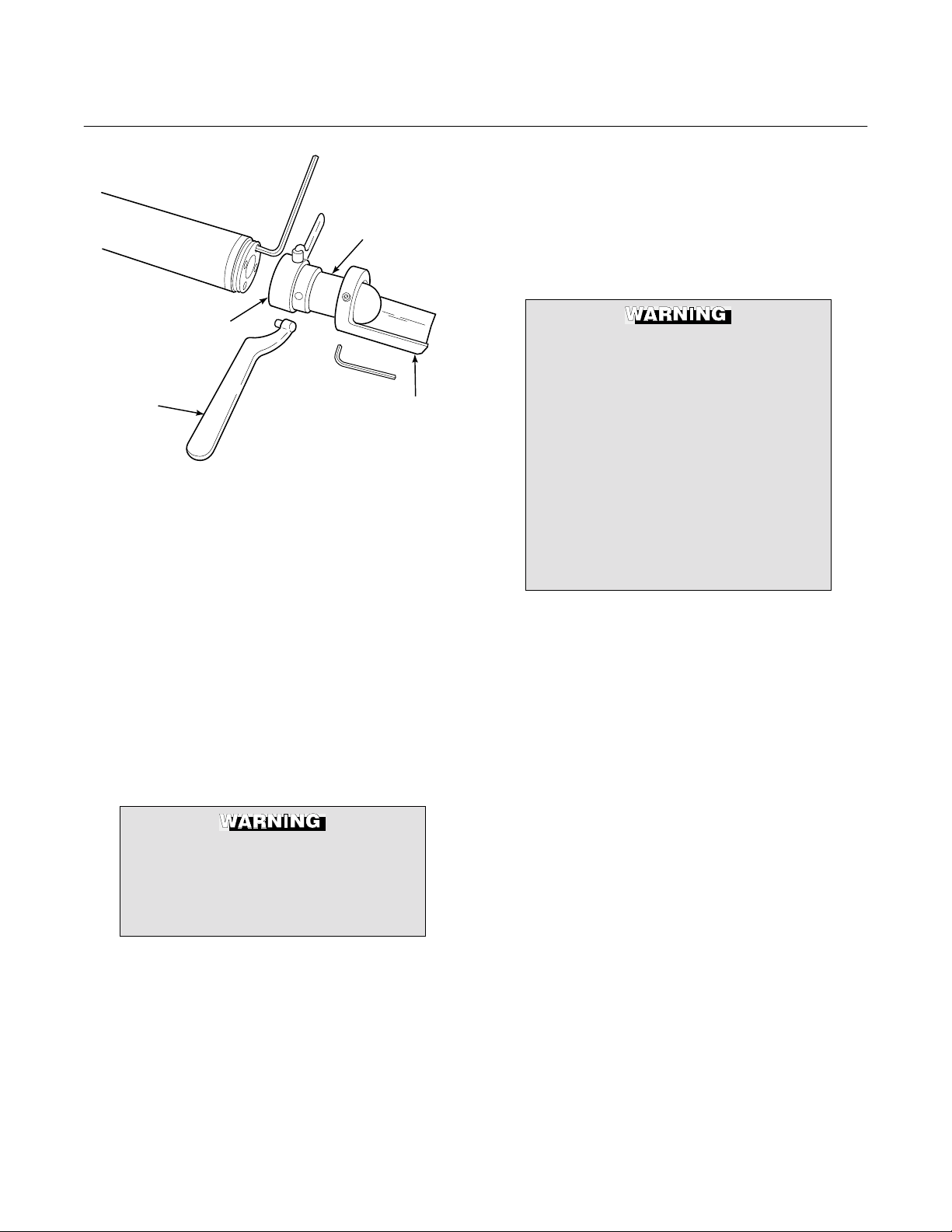
c. Snubber Diffusion Assembly
The snubber diffusion assembly protects
the cell from heavy particles and isolates
the cell from changes in temperature. The
snubber assembly threads onto the cell and
flange assembly. Pin spanner wrenches
An optional ceramic diffusor element and
vee deflector shown in Figure 1-6, is available. The ceramic diffusor assembly is also
available in a flame arresting version to
keep heat from the cell from igniting flue
gases.
(probe disassembly kit 3535B42G01) are
applied to holes in the diffusion element hub
to remove or install the snubber assembly.
1-6 Description and Specifications Rosemount Analytical Inc. A Division of Emerson Process Management
World Class 3000
1
Instruction Manual
IB-106-300DR Rev. 3.3
February 2000
is noted in the calibration data sheet supplied with each probe.
DIFFUSION
ELEMENT
HUB
PIN
WRENCH
VEE
DEFLECTOR
21240024
Figure 1-6. Optional Ceramic Diffusor and Vee
Deflector Assembly
Systems that use an abrasive shield require
a special diffusor assembly with a hub that
is grooved to accept two dust seal gaskets.
This special diffusor is available in both
snubber and ceramic versions. See Probe
Options, paragraph 1-8.
d. Cell – General
The components which make up the cell are
machined to close tolerances and assembled with care to provide accurate oxygen
measurements. Any replacement requires
attention to detail and care in assembly to
provide good results.
Every probe should be calibrated and
checked after repair or replacement of cell,
pad and wire, heater, and thermocouple, or
after disassembly of the probe.
There are two styles of the heater/strut
inner probe assembly. P/Ns
3D39441G06 through G10 identify the
44 V heater design. P/Ns 3D39441G01
through G05 and G11 through G15
identify the 115 V heater design. Both
styles look the same. When replacing
a strut, be sure the replacement has
the same part number as the original.
A stainless steel tag is attached to the
inner probe assembly to identify the
115V design. Operating a probe on the
wrong heater voltage can cause injury
or severe damage to equipment.
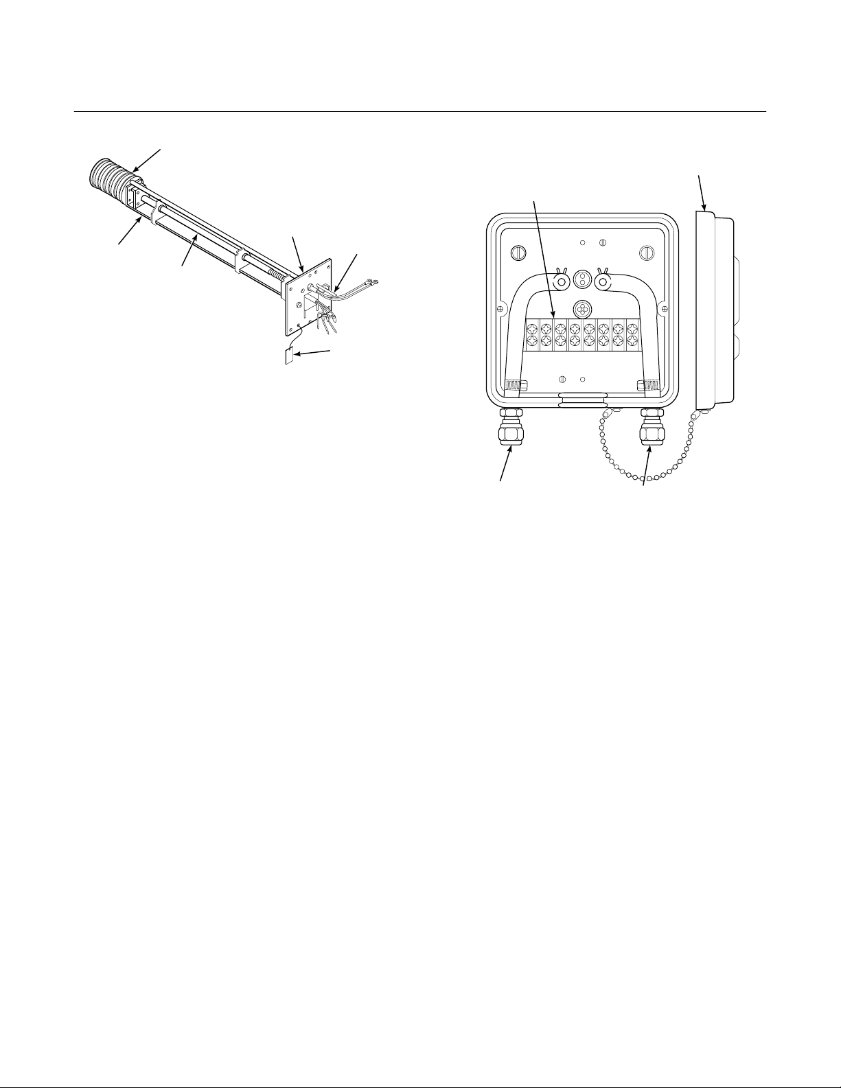
1-5 PROBE INTERIOR
The inner probe assembly, Figure 1-7, consists
of six main parts:
a. Ceramic support rod with four holes running
through the length. The holes serve as insulated paths for the cell signal wire and
thermocouple wires.
b. A heater that is helically wrapped on a
quartz support cylinder and insulated.
Failure to follow the instructions in
this manual could cause danger to
personnel and equipment. Read and
follow instructions in this manual
c. A chromel-alumel thermocouple which acts
as the sensing element for the temperature
controller. (Not visible in Figure 1-7; located
within ceramic support rod.)
carefully.
d. A platinum screen pad which forms electri-
The oxygen probe includes an inner electrode for the cell assembly. It consists of a
platinum pad and a platinum/inconel composite wire which produces the cell constant
offset voltage described in the Nernst equation.
With this pad and wire, the constant will be
between -10 and +15 mV. The cell constant
Rosemount Analytical Inc. A Division of Emerson Process Management Description and Specifications 1-7
cal contact with the inner electrode of the
electrochemical cell. (Not visible in Figure
1-7; located at end of ceramic support rod.)
The pad is attached to an inconel/stainless
steel wire which carries the signal to the
terminal strip.
e. A V-strut assembly to give support to the
inner probe assembly.
Instruction Manual
IB-106-300DR Rev. 3.3
February 2000
World Class 3000
HEATER
INSULATING
GASKET
V-STRUT
CERAMIC
SUPPORT
ROD
Figure 1-7. Inner Probe Assembly
f. A tube to carry reference gas to the cell.
Refer to Section 4, Maintenance and Service,
for repair procedures for probe components.
1-6 JUNCTION BOX
The junction box, Figure 1-8, is positioned at the
external end of the probe and contains a terminal strip for electrical connections and fittings for
reference and calibration gases. Fittings are for
0.250 inch stainless steel tubing on American
units, and 6 mm tubing on European units. The
calibration fitting has a seal cap which must remain in place except during calibration. A tubing
fitting is also supplied to be used with the
calibration gas supply during calibration.
If the calibration gas bottles will be permanently
hooked up to the probe, a manual block valve is
required at the probe (between the calibration
fitting and the gas line) to prevent condensation
of flue gas down the calibration gas line.
During operation and calibration, reference gas
is supplied through the reference gas fitting to
the reference side of the cell. This gives the
REFERENCE
GAS TUBE
TAG
21220004
PROBE
JUNCTION BOX
COVER
TERMINAL
STRIP
CALIBRATION
GAS FITTING
REFERENCE
GAS FITTING
21240029
Figure 1-8. Junction Box
system a known quantity of oxygen with which
to compare the oxygen level in the process gas.
Though ambient air can be used for this purpose, accuracy can only be assured if a
reference gas air set is used.
During calibration, two gases of different known
oxygen concentrations are injected one at a
time through the calibration gas fitting. Stainless steel tubing delivers this gas to the process
side of the cell. In a healthy cell, the difference
in oxygen pressure from the process side to the
reference side of the cell will cause a millivolt
output proportional to the difference in oxygen
levels. The electronics unit can use the two millivolt outputs caused by the two calibration
gases for either automatic or semi-automatic
calibration.
1-8 Description and Specifications Rosemount Analytical Inc. A Division of Emerson Process Management

World Class 3000
1
Do not attempt to remove a process
gas sample through either gas fitting.
Hot gases from the process would
damage gas hoses in the junction box.
1-7 CABLE ASSEMBLY
The Westinghouse and Rosemount systems
use a 7-conductor cable to connect the probe to
the electronics package. Standard length for this
cable is 20 ft (6 m), but lengths up to 150 ft
(45 m) are available. The seven conductors
include one shielded pair of wires for the cell
millivolt signal, one shielded pair of type K wires
for the thermocouple, and three individual
16-gauge wires for the heater and for ground.
The assembled conductors are wrapped by a
TM
Teflon
jacket and braided stainless steel
Instruction Manual
IB-106-300DR Rev. 3.3
TM
shield. The Teflon
ing is suitable for high temperature use. All
metal shields are isolated at the probe end and
connect by drain wires to ground at the
electronics.
1-8 PROBE OPTIONS
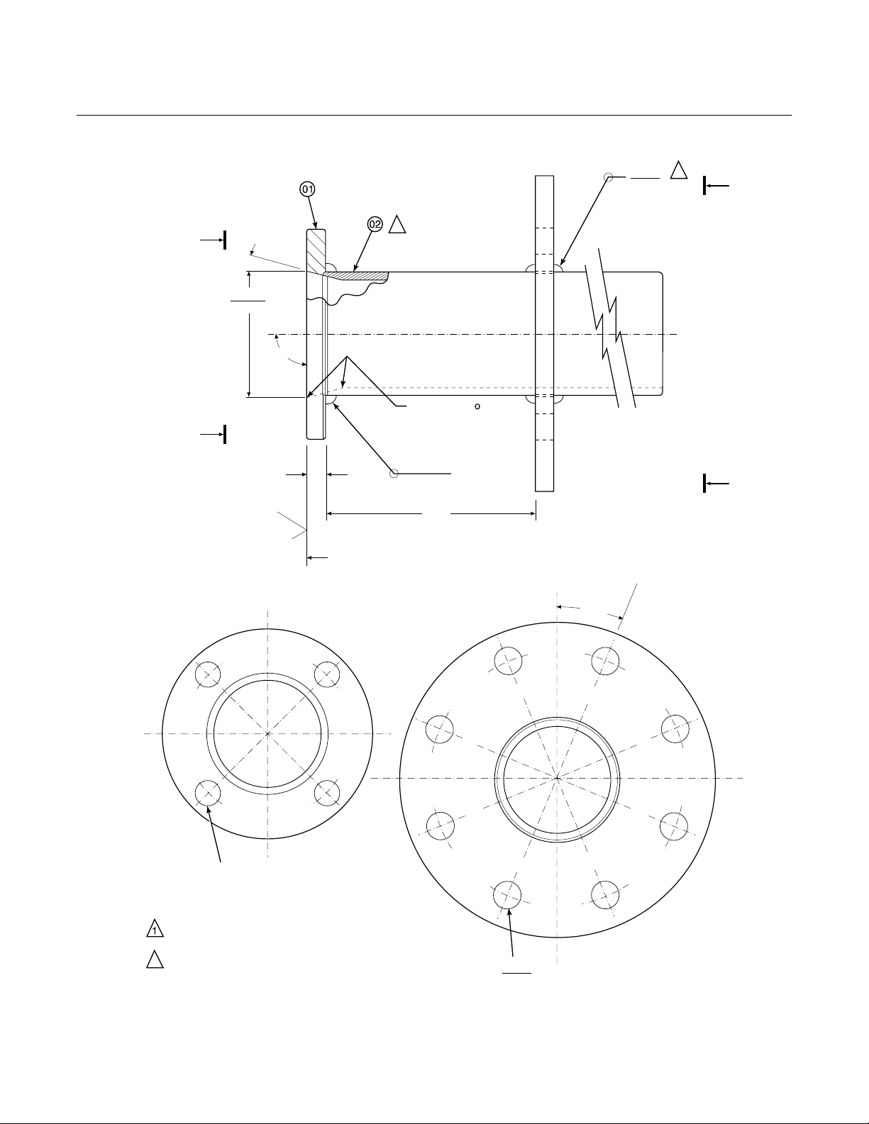
a. Abrasive Shield Assembly
The abrasive shield assembly, Figure 1-9, is
a stainless-steel tube that surrounds the
probe assembly. The shield protects the
probe against particle abrasion and corrosive condensations, provides a guide for
ease of insertion, and acts as a probe position support, especially for longer length
probes. The abrasive shield assembly uses
a modified diffusion and vee deflector assembly fitted with dual dust seal packing.
and stainless steel jacket-
February 2000
Rosemount Analytical Inc. A Division of Emerson Process Management Description and Specifications 1-9
Instruction Manual
IB-106-300DR Rev. 3.3
February 2000
World Class 3000
0.187
0.187
2
1
B
A
o
15
03.584
03.554
o
90
ON INSIDE BREAK
FOR SMOOTH
A
0.45 MIN
125
SKIN CUT FACE FOR 90
ROUNDED EDGE ON
BOTH ENDS OF
CHAMFER.
6.00
0.187
o
/
B
NOTES:
VIEW A
o
/
0.75 THRU 4 PLS.
EQ SP ON 4.75 B.C.
WELD ON BOTH SIDES WITH EXPANDING
CHILL BLOCK.
2
BEFORE WELDING, BUTT ITEM 2 WITH
ITEM 1 AS SHOWN.
o
/
Figure 1-9. Abrasive Shield Assembly
VIEW B
o
22.5
0.745
DIA ON A 7.50 DIA B.C. (REF)
0.755
P0009
1-10 Description and Specifications Rosemount Analytical Inc. A Division of Emerson Process Management
Loading...