

Manual Supplement: Rosemount Guided Wave Radar Transmitters in Upstream Applications-Best Practices User Guide
Table of contents
 Loading...
Rosemount Manual Supplement: Rosemount Guided Wave Radar Transmitters in Upstream Applications-Best Practices User Guide Manuals & Guides

Reference Manual
00809-0600-4811, Rev AA
February 2009
Rosemount Guided Wave Radar
Transmitters in Upstream Applications
Best Practices User Guide
www.rosemount.com

Reference Manual
00809-0600-4811, Rev AA
February 2009
Rosemount Radar Level Transmitters
Rosemount Guided Wave Radar
Transmitters in Upstream
Applications
Best Practices Users Guide
The products described in this document are NOT designed for nuclear-qualified
applications.
Using non-nuclear qualified products in applications that require nuclear-qualified hardware
or products may cause inaccurate readings.
For information on Rosemount nuclear-qualified products, contact your local Rosemount
Sales Representative.
This product is designed to meet FCC and R&TTE requirements for a non-intentional
radiator. It does not require any licensing whatsoever and has no tank restrictions
associated with telecommunications issues.
This device complies with part 15 of the FCC rules. Operation is subject to the following two
conditions: (1) This device may not cause harmful interference, and (2) this device must
accept any interference received, including interference that may cause undesired
operation.
Rosemount 3300 Series Guided Wave Radar Level and Interface Transmitters may be protected by one or
more of the following U.S. Patent Nos. 5,955,684; 6,148,681; 6,198,424; 6,373,261 and other patents issued or
pending in the U.S. and other countries. May depend on model.
Rosemount 5300 Series High Performance Guided Wave Radar Transmitters may be protected by one or more
of the following U.S: Patent Nos. 6,148,681; 5,955,684; 6,295,018; 6,198,424; 6,972,712; 6,842,139; 6,700,530
and other patents issued or pending in the U.S. and other countries. May depend on model.
Cover Photo: cover_combined 2.jpg
www.rosemount.com


Reference Manual
00809-0600-4811, Rev AA
February 2009
Rosemount Radar Level Transmitters
Table of Contents
SECTION 1
Introduction
SECTION 2
Installation
Considerations
SECTION 3
Upstream Applications
Introduction . . . . . . . . . . . . . . . . . . . . . . . . . . . . . . . . . . . . . . . . . . . . . 1-1
System Integration. . . . . . . . . . . . . . . . . . . . . . . . . . . . . . . . . . . . . . . . 1-2
Safety messages . . . . . . . . . . . . . . . . . . . . . . . . . . . . . . . . . . . . . . . . . 2-1
Introduction . . . . . . . . . . . . . . . . . . . . . . . . . . . . . . . . . . . . . . . . . . . . . 2-2
Mechanical Installation . . . . . . . . . . . . . . . . . . . . . . . . . . . . . . . . . . . . 2-2
Recommended Mounting Position . . . . . . . . . . . . . . . . . . . . . . . . . 2-2
Transition Zones. . . . . . . . . . . . . . . . . . . . . . . . . . . . . . . . . . . . . . . 2-5
Process Connections . . . . . . . . . . . . . . . . . . . . . . . . . . . . . . . . . . . 2-7
Electrical Installation . . . . . . . . . . . . . . . . . . . . . . . . . . . . . . . . . . . . . 2-12
Rosemount 3300 Series: HART Version . . . . . . . . . . . . . . . . . . . 2-12
Rosemount 3300 Series: Modbus Version . . . . . . . . . . . . . . . . . . 2-13
PC Communication with MA(+) MB(-) . . . . . . . . . . . . . . . . . . . . . 2-14
Cathodic Protection . . . . . . . . . . . . . . . . . . . . . . . . . . . . . . . . . . . 2-15
Rosemount 5300 Series: HART Version . . . . . . . . . . . . . . . . . . . 2-16
Rosemount 5300 Series: Foundation™ fieldbus Version. . . . . . . 2-18
Specific Applications . . . . . . . . . . . . . . . . . . . . . . . . . . . . . . . . . . . . . . 3-1
Separators . . . . . . . . . . . . . . . . . . . . . . . . . . . . . . . . . . . . . . . . . . . . . . 3-2
Horizontal separator (bullet tank) . . . . . . . . . . . . . . . . . . . . . . . . . . 3-2
Vertical separator (vertical cylinder tank) . . . . . . . . . . . . . . . . . . . . 3-3
Output measurement at different interface levels. . . . . . . . . . . . . . 3-4
Production/Slop Tanks. . . . . . . . . . . . . . . . . . . . . . . . . . . . . . . . . . . . . 3-7
Vertical cylinder . . . . . . . . . . . . . . . . . . . . . . . . . . . . . . . . . . . . . . . 3-7
Slop tanks . . . . . . . . . . . . . . . . . . . . . . . . . . . . . . . . . . . . . . . . . . . . . . 3-9
Underground or open pit. . . . . . . . . . . . . . . . . . . . . . . . . . . . . . . . . 3-9
SECTION 4
Commissioning
SECTION 5
Troubleshooting
www.rosemount.com
Safety messages . . . . . . . . . . . . . . . . . . . . . . . . . . . . . . . . . . . . . . . . . 4-1
Introduction . . . . . . . . . . . . . . . . . . . . . . . . . . . . . . . . . . . . . . . . . . . . . 4-2
Commissioning . . . . . . . . . . . . . . . . . . . . . . . . . . . . . . . . . . . . . . . . . . 4-2
Trim Near Zone . . . . . . . . . . . . . . . . . . . . . . . . . . . . . . . . . . . . . . . 4-2
Store Backup and Verification Files . . . . . . . . . . . . . . . . . . . . . . . . 4-4
Plotting the Measurement Signal. . . . . . . . . . . . . . . . . . . . . . . . . . . . . 4-5
Plotting the Measurement Signal for the Rosemount 3300 Series. 4-5
Plotting the Measurement Signal for the Rosemount 5300 Series. 4-6
Differences Between Plots in RRM and RCT . . . . . . . . . . . . . . . . . 4-9
Safety messages . . . . . . . . . . . . . . . . . . . . . . . . . . . . . . . . . . . . . . . . . 5-2
Rosemount 3300 Threshold Settings . . . . . . . . . . . . . . . . . . . . . . . . . 5-3
Case 1 - Level measurements . . . . . . . . . . . . . . . . . . . . . . . . . . . . 5-3
Case 2 - Level & Interface measurements . . . . . . . . . . . . . . . . . . . 5-4
Disturbances From Nozzle . . . . . . . . . . . . . . . . . . . . . . . . . . . . . . . . . 5-5
Upper Null Zone adjustment. . . . . . . . . . . . . . . . . . . . . . . . . . . . . . 5-5

Rosemount Radar Level Transmitters
Nozzle influence . . . . . . . . . . . . . . . . . . . . . . . . . . . . . . . . . . . . . . . 5-6
Near Zone Threshold . . . . . . . . . . . . . . . . . . . . . . . . . . . . . . . . . . . 5-7
Rosemount 5300 Threshold Settings . . . . . . . . . . . . . . . . . . . . . . . . 5-10
Device status . . . . . . . . . . . . . . . . . . . . . . . . . . . . . . . . . . . . . . . . . . . 5-12
Device Status: Rosemount 3300 Series. . . . . . . . . . . . . . . . . . . . 5-12
Device Status: Rosemount 5300 Series. . . . . . . . . . . . . . . . . . . . 5-13
Reference Manual
00809-0600-4811, Rev AA
February 2009
SECTION 6
Verification Procedure
APPENDIX A
Model Code Information
Introduction . . . . . . . . . . . . . . . . . . . . . . . . . . . . . . . . . . . . . . . . . . . . . 6-1
Verification Procedure . . . . . . . . . . . . . . . . . . . . . . . . . . . . . . . . . . . . . 6-2
Self Test . . . . . . . . . . . . . . . . . . . . . . . . . . . . . . . . . . . . . . . . . . . . . 6-2
Rosemount 3300 Plot Verification . . . . . . . . . . . . . . . . . . . . . . . . . 6-3
Rosemount 5300 Plot Verification . . . . . . . . . . . . . . . . . . . . . . . . . 6-4
Diagnostics . . . . . . . . . . . . . . . . . . . . . . . . . . . . . . . . . . . . . . . . . . . . . 6-5
Model Code 3302 and 5302, Level and Interface in Liquids . . . . . . . . A-2
Model Code Example - Rosemount 3300 Series . . . . . . . . . . . . . A-5
Model Code Example - Rosemount 5300 Series . . . . . . . . . . . . . . A-5
TOC-2

Reference Manual
00809-0600-4811, Rev AA
February 2009
Rosemount Radar Level Transmitters
Section 1 Introduction
Introduction . . . . . . . . . . . . . . . . . . . . . . . . . . . . . . . . . . . . . page 1-1
System Integration . . . . . . . . . . . . . . . . . . . . . . . . . . . . . . . page 1-2
INTRODUCTION This document describes some of the best practices learned during the
installation of thousands of Rosemount Guided Wave Radar level transmitters
in upstream oil and gas applications. However, it is not a complete set of
instructions; for more detailed information, refer to the respective product
manual:
• Rosemount 5300 Series Reference Manual
(Document No. 00809-0100-4530)
• Rosemount 3300 Series Reference Manual
(Document No. 00809-0100-4811)
The Rosemount 3300 Series and 5300 Series Guided Wave Radar
transmitters are Time Domain Reflectometry Pulsed Radar level instruments.
They are utilized in the Oil and Gas industry for the measurement of
hydrocarbons and water in production and separator tanks. Both the
Rosemount 3300 and 5300 Series have the ability to measure overall level as
well as interface level in the vessels. They can be installed in several different
configurations including flanges, threaded, and side-mounted connections.
The Rosemount 3300 can transmit measurement values and diagnostics with
the 4-20 mA HART
protocols. The Rosemount 5300 is a high performance transmitter and can
transmit measurement values and diagnostics with the 4-20 mA HART and
F
OUNDATION™ fieldbus communication protocols.
This document describes which series, models, and probes to use on the
various applications within upstream Oil and Gas fields, and therefore serves
as a selection guideline specific to these applications and needs. Local
restrictions, regulations, or best practices may also apply and should be taken
into consideration.
®
and RS-485 Modicon RTU Modbus communication
www.rosemount.com
Rosemount Radar Level Transmitters
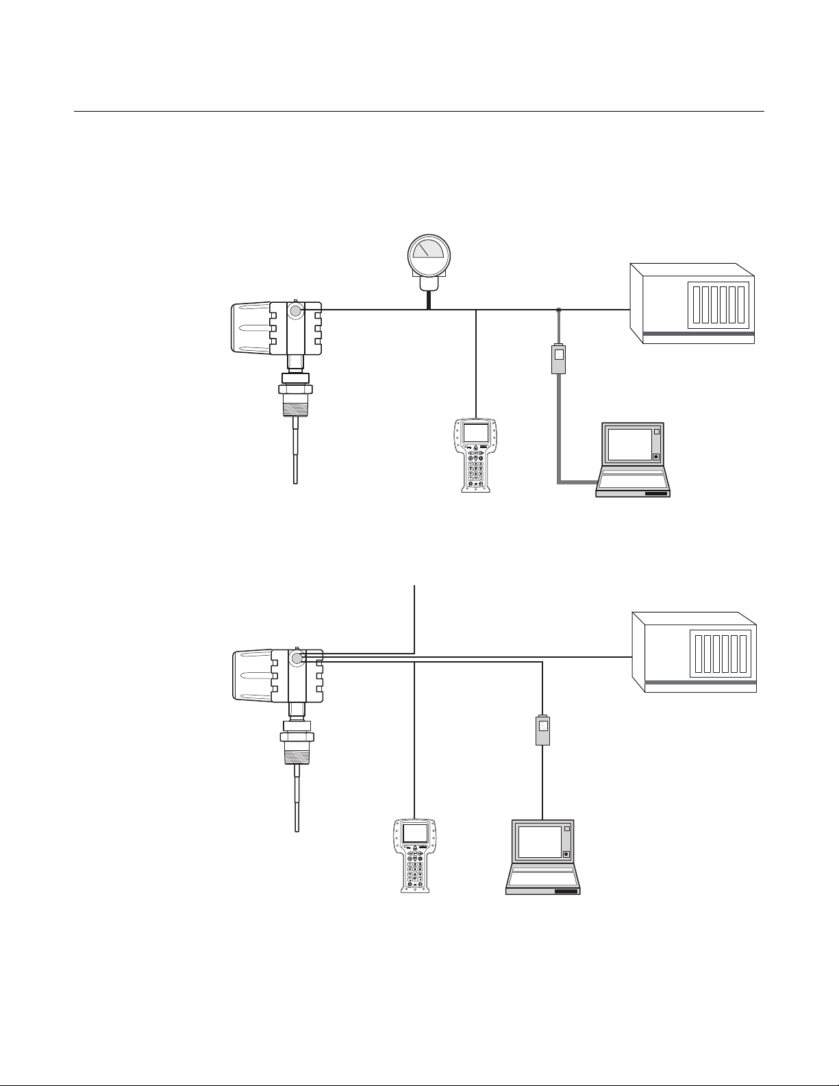
Control
System/PLC
HART
Modem
PC
Rosemount 3300 Series
transmitter
375 Field
Communicator
4-20 mA/HART
Modbus Control
System/PLC
HART
Modem
PC
Power
375 Field
Communicator
Max. cable length is
4000 ft. (1200 m)
MODBUS
Rosemount 3300 Series
transmitter
SYSTEM INTEGRATION
Figure 1-1. Rosemount 3300
Series: HART system.
Reference Manual
00809-0600-4811, Rev AA
February 2009
Figure 1-2. Rosemount 3300
Series: MODBUS system.
1-2

Reference Manual
Rosemount
5300 Series
Transmitter
Display
4-20 mA / HART
375 Field
Communicator
3 x 4-20 mA
Tri-loop
Control
System
HART
Modem
PC with Rosemount
RadarMaster
Host / DCS System (e.g. DeltaV
®)
Maintenance
H2 - High Speed Field Bus
H1 - Low Speed Field Bus
6234 ft. (1900 m) maximum
(depending upon cable
characteristics)
Fieldbus
Modem
PC with Rosemount
RadarMaster
Display
(option)
Rosemount 5601
Rosemount 5401
Rosemount 5301
375 Field
Communicator
Note:
Intrinsically safe
installations
may allow fewer
devices per I.S.
barrier due to
current
limitations.
00809-0600-4811, Rev AA
February 2009
Figure 1-3. Rosemount 5300
Series:
HART system.
Rosemount Radar Level Transmitters
Figure 1-4. Rosemount 5300
Series - F
OUNDATION™ fieldbus
system.
1-3

Rosemount Radar Level Transmitters
Reference Manual
00809-0600-4811, Rev AA
February 2009
1-4

Reference Manual
00809-0600-4811, Rev AA
February 2009
Rosemount Radar Level Transmitters
Section 2 Installation Considerations
Safety messages . . . . . . . . . . . . . . . . . . . . . . . . . . . . . . . . . page 2-1
Introduction . . . . . . . . . . . . . . . . . . . . . . . . . . . . . . . . . . . . . page 2-2
Mechanical Installation . . . . . . . . . . . . . . . . . . . . . . . . . . . page 2-2
Electrical Installation . . . . . . . . . . . . . . . . . . . . . . . . . . . . . page 2-12
SAFETY MESSAGES Procedures and instructions in this section may require special precautions to
ensure the safety of the personnel performing the operations. Information that
raises potential safety issues is indicated by a warning symbol ( ). Please
refer to the following safety messages before performing an operation
preceded by this symbol.
Explosions could result in death or serious injury.
Verify that the operating environment of the gauge is consistent with the appropriate
hazardous locations certifications.
Before connecting a HART-based communicator in an explosive atmosphere, make
sure the instruments in the loop are installed in accordance with intrinsically safe or
non-incendive field wiring practices.
Do not remove the gauge cover in explosive atmospheres when the circuit is alive.
Failure to follow safe installation and servicing guidelines could result in death or
serious injury.
Make sure only qualified personnel perform the installation.
Use the equipment only as specified in this manual. Failure to do so may impair the
protection provided by the equipment.
Do not perform any service other than those contained in this manual unless you are
qualified.
High voltage that may be present on leads could cause electrical shock.
Avoid contact with leads and terminals.
Make sure the main power to the Rosemount 3300 / 5300 Transmitter is off and the lines
to any other external power source are disconnected or not powered while wiring
the gauge.
Probes covered with plastic and/or with plastic discs may generate an ignition-capable
level of electrostatic charge under certain extreme conditions. Therefore, when the
probe is used in a potentially explosive atmosphere, appropriate measures must be
taken to prevent electrostatic discharge.
Process leaks could result in death or serious injury.
Make sure that the transmitter is handled carefully. If the Process Seal is damaged, gas
might escape from the tank if the transmitter head is removed from the probe.
www.rosemount.com

Reference Manual
00809-0600-4811, Rev AA
Rosemount Radar Level Transmitters
February 2009
INTRODUCTION In addition to selecting the appropriate radar level transmitter, mechanical
installation is one of the most critical steps of the commissioning procedure.
When done correctly, the subsequent transmitter configuration will be
considerably simplified.
The main focus of this section is to provide a framework for installations in a
variety of tanks and process connections typically found in the upstream oil
and gas industry.
MECHANICAL INSTALLATION
Recommended Mounting Position
Figure 2-1. Mounting Position.
To find an appropriate mounting position for the transmitter, consider the
conditions of the tank. The transmitter should be mounted so that turbulence
from disturbing objects is reduced. If turbulence is present, the probe may
need to be anchored to the bottom.
2-2
Guidelines to be considered when mounting the transmitter:
• Do not mount close to inlet pipes
• If the probe sways because of turbulent conditions in the tank, the
probe should be anchored to the tank bottom. In these applications, the
best option is anchoring with a Magnet fastened to the weight
• Avoid mounting close to internal objects that are within 6 in. (150 mm)
from probe at any time
• The probe should not come into contact with the nozzle or other objects
in the tank
NOTE!
Violent fluid movements can cause forces that could break rigid probes.
Reference Manual
Magnet
Clamps
00809-0600-4811, Rev AA
February 2009
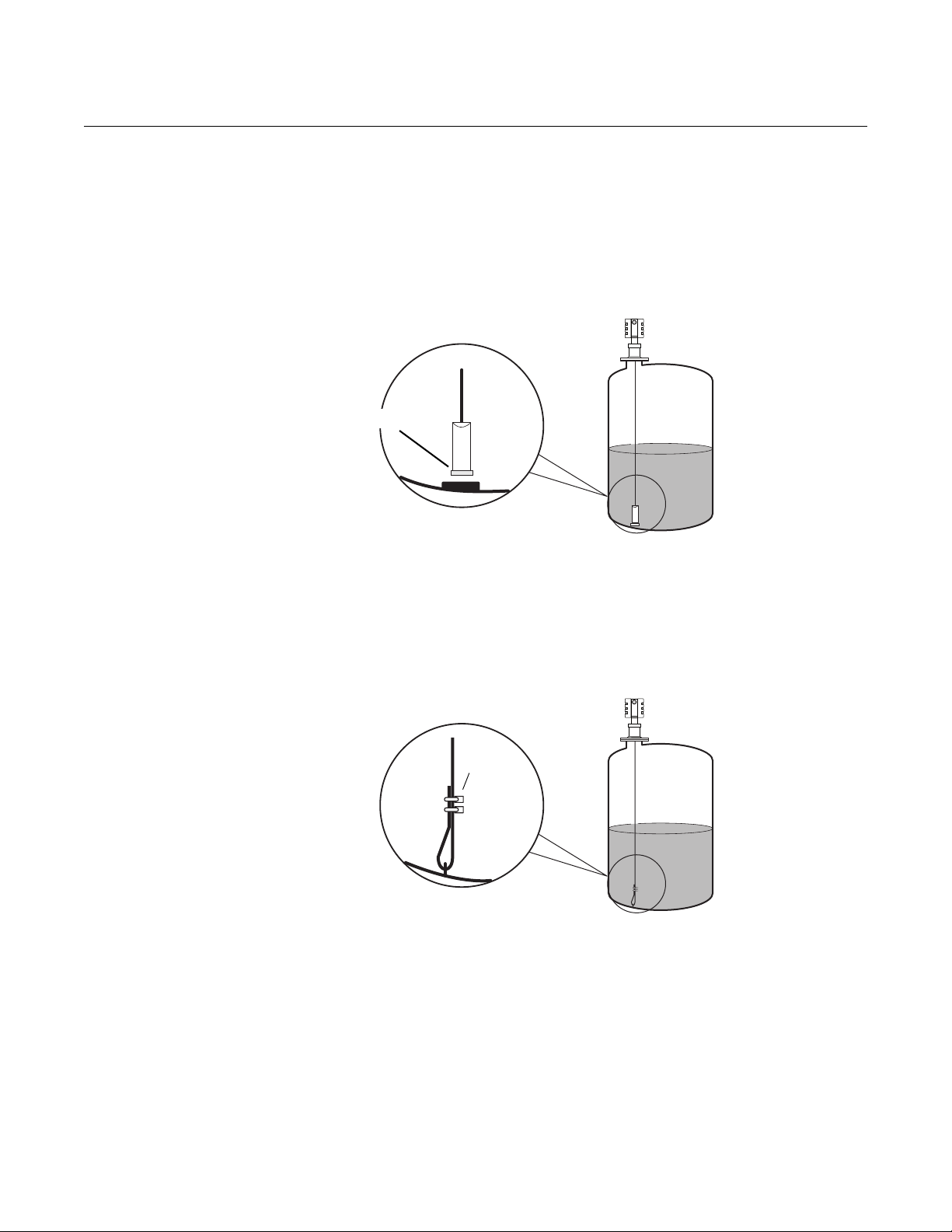
Figure 2-2. Anchoring the probe
with a magnet.
Rosemount Radar Level Transmitters
Anchoring a Flexible Single Lead probe
A magnet can be fastened to a threaded (M8x14) hole at the end of the
weight. Placing a metal plate beneath the magnet, as illustrated in Figure 2-2,
will help to guide the probe.
Magnets should not be used on long nozzle applications because the magnet
could attach to the side of the nozzle during installation.
Figure 2-3. Anchoring the probe
through a welded eye.
The probe rope can also be used for anchoring. The probe rope can be pulled
through a suitable anchoring point, e.g. a welded eye and fastened with two
clamps. The length from the underside of the flange to the top clamp should
be used to configure the probe length.
2-3
Rosemount Radar Level Transmitters
Make sure that the probe
does not come into
contact with the chamber
wall, e.g. by using a
centering disk.
A clearance
distance of 1 in.
(25 mm) between
the probe end and
the cage bottom is
recommended.
Installation in pipes
A centering disk is recommended when installing in pipes to prevent the
probe from contacting the chamber wall. The disk is attached to the end of the
probe to keep the probe centered in the chamber. The discs are available in
stainless steel (SST) and PTFE. The PTFE option is recommended for most
applications and the SST centering disk is used for high temperature
operations.
Figure 2-4. Improper and proper
probe positions.
Reference Manual
00809-0600-4811, Rev AA
February 2009
2-4
To avoid bending the probe (rigid probes) or twisting and coming in contact
with the chamber wall (flexible probes), a small clearance distance of 1 in.
(25 mm) between the centering disk and chamber bottom is recommended. It
should be selected with a dome shaped chamber bottom in mind, which may
prevent the centering disk from reaching the bottom.
Side-pipe locations and the effective measurement range are determined by
the mating tank connections. There are no constraints on the diameter of the
side-pipes, but build-up and clogging should be considered. Also the inlet
pipes should not protrude into the chamber since they may interfere with the
radar measurement. Always use the same construction material for the
chamber and the tank, otherwise, mechanical tensions can arise in the
side-connections.
The recommended chamber diameter is 3 in. (75 mm) or 4 in. (100 mm).
Chambers with a diameter less than 3 in. (75 mm) may have build-up
problems and it may also be difficult to center the probe. Chambers larger
than 6 in. (150 mm) can be used, but provide no advantages for the radar
measurement.
With the Rosemount 3300 / 5300 Series, single probes are recommended for
use in 3 in. (75 mm) and 4 in. (100 mm) chambers. Other probe types are
susceptible to build-up and should not be used in this application.
The probe must not touch the chamber wall and should extend the full height
of the chamber, but it does not need to touch the bottom of the chamber.
Probe type selection depends on the probe length:

Reference Manual
00809-0600-4811, Rev AA
February 2009
Rosemount Radar Level Transmitters
Less than 3 ft. (1 m): Use Single Rigid Probe and no centering disk is
needed. The transition zones and the height of the weight will limit the use of
single flexible probes shorter than 3 ft. (1 m).
Between 3 ft. (1 m) and 10 ft. (3 m): Use either Rigid Single or Flexible
Single Probe with the weight and centering disk. Rigid Single has smaller
transition zones, while the Flexible Single requires less head-space during
installation and is less likely to be damaged.
More than 10 ft. (3 m): Use Flexible Single Probe with a weight and centering
disk.
Light hydrocarbon applications not in chambers: Use the Rosemount
5300 Series with either a Rigid Single or Flexible Single Probe. In very light
hydrocarbons, the Rosemount 3300 signal loses too much energy on a single
probe. The Rosemount 5300 has more efficient and sensitive microwave
modules that increase signal strength. The 3300 will, however, work in light
hydrocarbon chamber applications, because chambers have similar physics
of propagation as the traditional coaxial style probe.
Transition Zones Transition zones, located at the very top and bottom of the probes, are
regions where measurement performance is reduced. Different factors affect
the size of the transition zones - probe type, centering disk or no centering
disk, and the material and media measured, as shown in Table 2-1.
Table 2-1. Transition Zones for
Rosemount 3300 and 5300
Series.
Dielectric
Constant
(2)
Upper
80 (water) 4 in. (10 cm) 4.3 in. (11.cm) 4 in. (10 cm) 4.3 in. (11 cm) 5.9 in. (15 cm) 4.3 in. (11 cm)
Transition
Zone
(3)
Lower
Transition
Zone
(1) Rigid Single Lead probe without SST centering disk or with PTFE centering disk.
(2) The distance from the upper reference point where measurements have reduced accuracy.
(3) The distance from the lower reference point where measurements have reduced accuracy.
(4) Note that the weight length adds to non-measurable area. For more information, see Dimensional Drawings in the Guided Wave Radar Level and Interface
Transmitter, Rosemount 3300 Series Product Data Sheet (Document No. 00813-0100-4811).
(5) The measuring range for the PTFE covered Flexible Single Lead probe includes the weight when measuring on a high dielectric media.
(6) Note that the weight length adds to non-measurable area. For more information, see Dimensional Drawings in the High Performance Guided Wave Radar,
Rosemount 5300 Product Data Sheet (Document No. 00813-0100-4530).
2 (oil) 4 in. (10 cm) 6.3 in. (16 cm) 4 in. (10 cm) 6.3 in. (16 cm) 20 in. (50 cm) 7.1 in. (18 cm)
80 (water) 2 in. (5 cm) 2 in. (5 cm) 2 in. (5 cm) 2 in. (5 cm) 2 in. (5 cm)
2 (oil) 4 in. (10 cm) 2.8 in. (7 cm) 8 in. (20 cm) 8 in. (20 cm) 4.7 in. (12 cm)
Rigid Single Lead
3300 5300 3300 5300 3300 5300
(1)
Rigid Single Lead, with
metallic centering disk
Flexible Single Lead
(4) (5)
0 in. (0 cm)
(4)
2 in. (5 cm)
(5) (6)
(6)
2-5
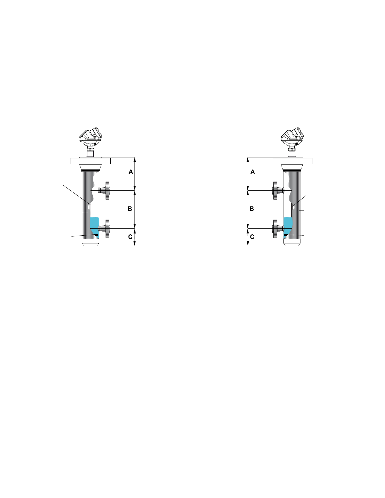
Rosemount Radar Level Transmitters
A > Upper transition zone
B = Effectice Measuring
Range, determined by
mating tank connections
C > Lower transition zone
including weight height
(for flexible probes) and
clearance distance
Single Flexible
for chambers
>= 3 ft. (1 m)
Probe/chamber
diameter must
be 3 in. or 4 in.
(7.5 cm or 10 cm)
Always use a
centering disk
Single Rigid
Probe/chamber
diameter must
be 3 in. or 4 in.
(7.5 cm or 10 cm)
Use centering
disks for probes
> 3 ft. (1 m)
The weight on the flexible probes reduces the measurement range.
Therefore, it is recommended to dimension the cage (A, C) so it does not
interfere with the effective measurement range (B). The transition zones also
limit the minimum probe length. See Figure 2-5 on page 2-6.
Figure 2-5. Measuring zones in
chambers.
Reference Manual
00809-0600-4811, Rev AA
February 2009
2-6

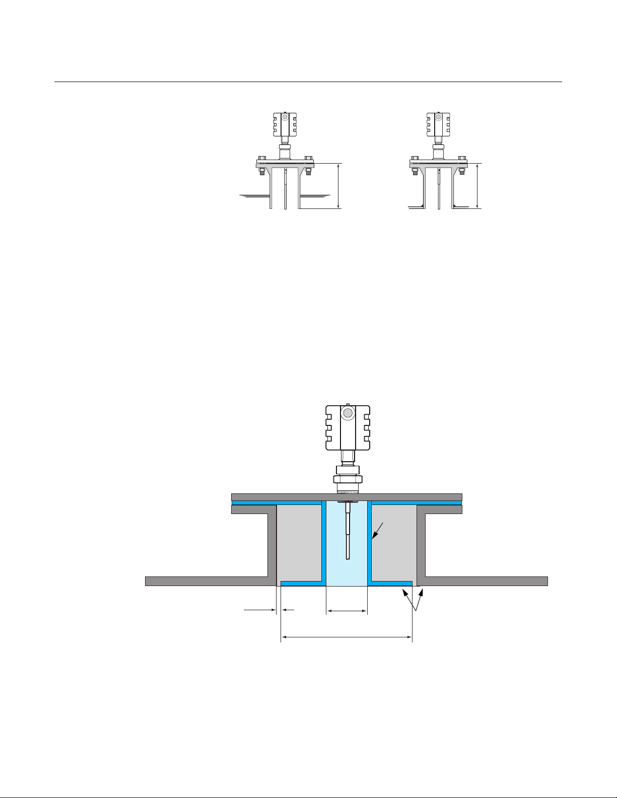
Reference Manual
UNZ H
Nozzle diameter (D)
Upper Null Zone (UNZ)
adjustments may be
needed for 2-in. (50 mm)
nozzles
Avoid nozzles with reducer
(unless using coaxial probe)
00809-0600-4811, Rev AA
February 2009
Rosemount Radar Level Transmitters
Process Connections There are a few different types of Process Connections used in these
applications. Below are some directions and guidelines on how to install and
what to consider for the various connections.
Flanged connections
Below are recommendations for the nozzle configuration and dimensions for
flanged installations on top of the tank/vessel.
Table 2-2. Nozzle
considerations.
Recommended Nozzle Diameter (D) 4-6 in. (100-150 mm)
Minimum Nozzle Diameter (D)
Maximum Nozzle Height (H) 4 in. (100 mm) + Nozzle Diameter
(1) An Upper Null Zone setup may be required to mask the nozzle, which may reduce
the measuring range.
Nozzle height H is measured from the flange to the bottom of the nozzle,
regardless of how the nozzle is attached to the tank roof as illustrated in
Figure 2-6.
Single (Rigid / Flexible)
(1)
2 in. (50 mm)
2-7
Rosemount Radar Level Transmitters
HH
Tank roof
Tank r o o f
< ½ in. (13 mm)
6 in.
(150 mm)
Approx. flush within ± 1 in. (25 mm)
No need to be more than 15 in.
(380 mm) even for very large nozzles
for nozzles less than
15 in. ( 380 mm)
Inner
nozzle
Figure 2-6. Definition of nozzle
height H.
10-in. (250 mm) or larger flange/manway connection
If a Rosemount 3300/5300 Series Guided Wave Radar with single lead probe
is installed in a 10-in. (250 mm) (DN250) high nozzle or larger, there may be
resonance and double bounce problems. This can lead to measurement
errors for products with low dielectric constants, so 10-in. (250 mm) nozzles or
larger should be avoided.
In cases where 10-in. (250 mm) nozzles or larger are used, install an inner
steel nozzle with a smaller diameter, as illustrated in Figure 2-7.
Reference Manual
00809-0600-4811, Rev AA
February 2009
Figure 2-7. Special installation
considerations for 10 inch
nozzles.
Flat tank roof installation is not affected by this phenomenon.
2-8

Reference Manual
3 or 4 in.
(75 or 100 mm)
1 ½ in. (37.5 mm) NPT
Do not use Teflon tape
or similar
non-conductive
materials in the
threaded connections.
These connections
must be able to provide
a ground connection
between the probe and
the tank.
00809-0600-4811, Rev AA
February 2009
Figure 2-8. The Rosemount
3300 / 5300 can be installed in a
3 or 4 in. (75 or 100 mm) tank
opening by using an adaper.
Rosemount Radar Level Transmitters
Threaded tank connection
Many Oil and Gas applications have 3-in. (75 mm) or 4-in. (100 mm) threaded
connections on top of the tank roof.
For this connection, install the Rosemount 3300 / 5300 transmitters with a
1 ½-in. ( 37.5 mm) NPT threaded connection (model code option RA). The
probe can be attached to a bushing or adapter piece, reducing the tank
opening from a 3-in. (75 mm) or 4 in. (100 mm) threaded connection to the
desired 1 ½-in. (37.5 mm) standard Rosemount 3300 / 5300 process
connection.
2-9
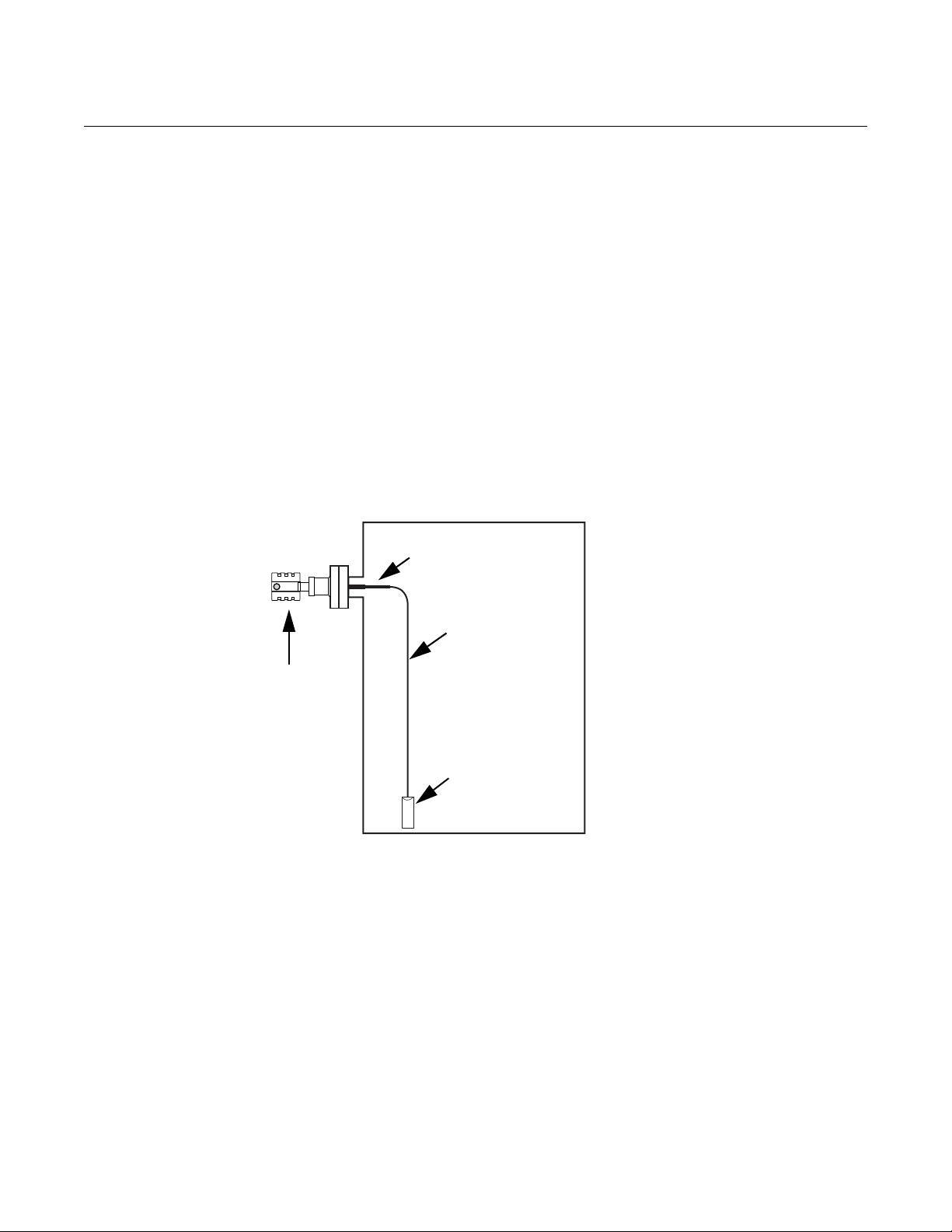
Rosemount Radar Level Transmitters
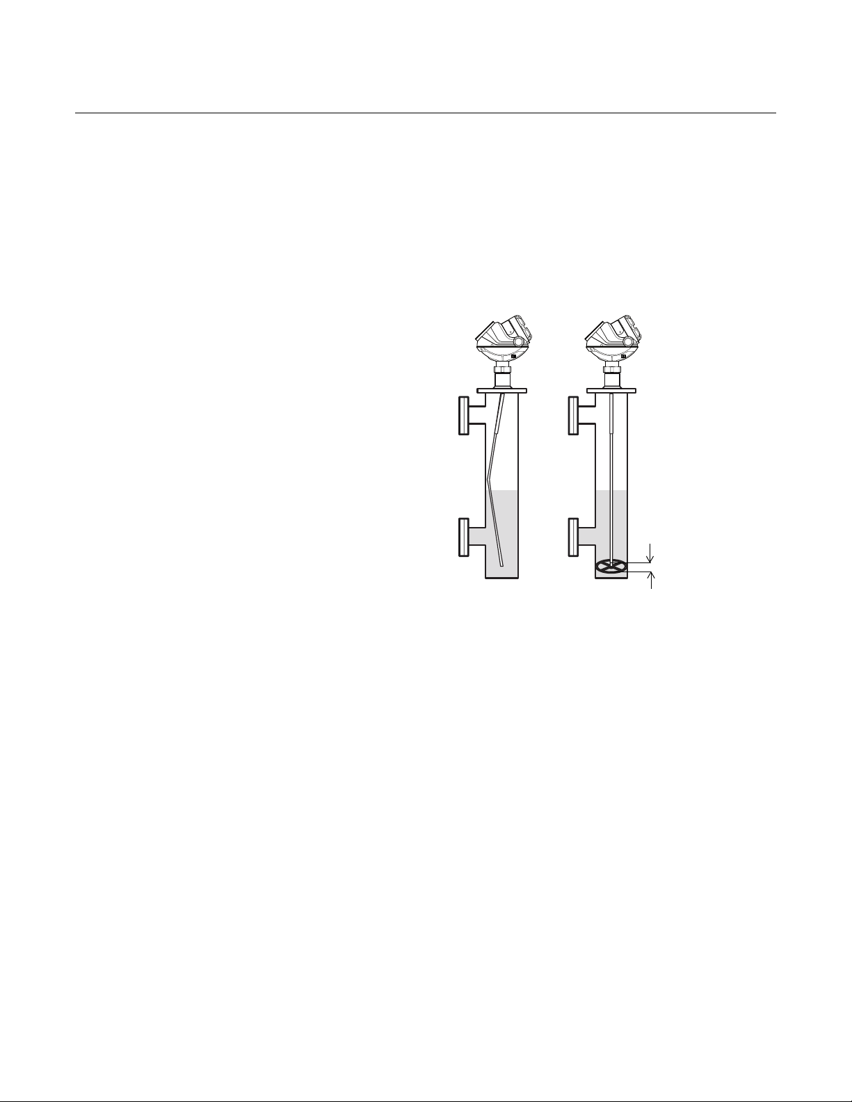
The illustration demonstrates the Long
Stud (LS) configuration in which the rigid
portion of the single flexible probe extends
the probe further into the vessel, thus
preventing the probe from contacting the
side of the vessel.
Rosemount 3300 or
5300 transmitter
Long Stud
Flexible Probe
Counter Weight
Side mounted process connection
In some cases, tanks might not have top process connections suitable for
installation of Guided Wave Radar units, so side mounted process
connections are a viable and reliable installation practice. Certain precautions
must be taken to ensure successful level measurements in these vessels.
Both flexible and rigid single lead probes can be utilized for these
installations.
A special mechanical configuration, Long Stud (model code option LS), can
be used for the Flexible Single Lead probe to prevent contact with walls or
nozzles. The Long Stud incorporates a longer rigid rod extension piece which
connects to the flexible portion of the probe. This is useful for side mounted
probes since it allows for the probe to extend further into the vessel before it is
bent vertically down towards the tank bottom. Figure 2-9 illustrates this type of
installation:
Figure 2-9. Side mounting with
Flexible Single Lead probe.
Reference Manual
00809-0600-4811, Rev AA
February 2009
2-10

Reference Manual
The single rigid probe is bent 90° at a
distance that will ensure that the probe
protrudes into the tank and away from
the tank wall.
Rigid Probe
90
° bend
Rosemount 3300 or
5300 transmitter
00809-0600-4811, Rev AA
February 2009
Figure 2-10. Side mounting with
Rigid Single Lead probe.
Rosemount Radar Level Transmitters
For side mounting with a Rigid Single Lead probe, the probe is bent at a 90°
angle to ensure that the probe extends into the tank and away from the tank
wall. Figure 2-10 illustrates this type of installation:
Non-metallic Process Connections
See “Non-metallic process connections“ on page 3-10.
2-11

Rosemount Radar Level Transmitters
For Explosion-proof/ Flameproof
applications the resistance
between the negative terminal on
the transmitter and the power
supply must not exceed 300
.
375 Field
Communicator
PC
Power Supply
Load Resistance 250
HART
modem
Rosemount 3300
Series Transmitter
Reference Manual
00809-0600-4811, Rev AA
February 2009
ELECTRICAL INSTALLATION
This is a brief description of the Rosemont 3300 and 5300 wiring procedure.
For more information, see the respective reference manual: Rosemount 3300
Series (Document No. 00809-0100-4811) and Rosemount 5300 Series
(Document No. 00809-0100-4530).
Rosemount 3300 Series:
HART
Version
The 3300 Series is a two-wire loop powered transmitter accepting power
supplies ranging from 11 Vdc to 42 Vdc. It uses 4-20 mA power superimposed
with a HART
signal. To connect the transmitter:
1. Make sure the power supply is disconnected.
2. Remove the cover on the transmitter housing terminal side (see label).
Do not remove the cover in explosive atmospheres when the circuit is
live. All power to the transmitter is supplied over the signal wiring.
3. Pull the cable through the cable gland/conduit.
4. Connect wires according to Figure 2-11 for non-intrinsically safe output.
Make sure that the transmitter housing is grounded in accordance with
national and local electrical codes. There are two grounding screw
connections provided. One is inside the Field Terminal side of the
housing identified by a ground symbol: , and the other is located on
top of the housing.
5. Attach and tighten the housing cover. Tighten the cable gland, plug and
seal any unused connections and connect the power supply.
Figure 2-11. Wiring diagram for non-intrinsically safe installations of the 3300.
2-12
For HART communication, a minimum load resistance of 250 within the
loop is required.
The power supply voltage ranges from V
Vdc to 42 Vdc where V
min
min
is the
minimum voltage given by:
11 V Non-hazardous locations certification
16 V Explosion-proof/flameproof certification

Reference Manual
RS-485 Bus
B
A
120
120
Power
Supply
HART -
HART +
In case it is the last transmitter on
the bus, connect the 120 terminator
resistor
120
00809-0600-4811, Rev AA
February 2009
Rosemount Radar Level Transmitters
Rosemount 3300 Series: Modbus Version
To connect the Rosemount 3300:
1. Make sure the power supply is disconnected.
2. Remove the cover on the transmitter housing terminal side (see label).
Do not remove the cover in explosive atmospheres when the circuit is
live. All power to the transmitter is supplied over the signal wiring.
3. Pull the cable through the cable gland/conduit. For the RS-485 bus use
shielded twisted pair wiring, preferably with an impedance of 120
(typically 24 AWG) to comply with the EIA-485 standard and EMC
regulations. Maximum cable length is 4000 ft. (1200 m).
4. Connect wires according to Figure 2-12 and Table 2-3. Connect the lead
that originates from the “A” line from the RS-485 bus to the terminal
marked MA (+), and the lead that originates from the “B” line to the
terminal marked MB (-). Make sure that the transmitter housing is
grounded in accordance with national and local electrical codes. There
are three grounding screw connections provided. Two are inside the
Field Terminal side of the housing identified by a ground symbol:
and the other is located on top of the housing.
5. If it is the last transmitter on the bus, connect the 120 termination
resistor.
6. Connect the leads from the positive side of the power supply to the
terminal marked PWR +, and the leads from the negative side of the
power supply to the terminal marked PWR -. The power supply cables
must be suitable for the supply voltage and approved for use in
hazardous areas, where applicable.
7. Attach and tighten the housing cover. Tighten the cable gland, plug and
seal any unused connections and connect the power supply.
,
Figure 2-12. Field Wiring Connection for the 3300 with Modbus.
2-13
Loading...