

Manual: SPS 4000 Single Probe Autocalibration Sequencer-Rev 1.1 | Rosemount
Table of contents
 Loading...
Rosemount Manual: SPS 4000 Single Probe Autocalibration Sequencer-Rev 1.1 | Rosemount Manuals & Guides

Instruction Manual
IB-106-340AC Rev. 1.1
April 2001
SPS 4000
Single Probe
Autocalibration Sequencer
http://www.processanalytic.com

ESSENTIAL INSTRUCTIONS
READ THIS PAGE BEFORE PROCEEDING!
Rosemount Analytical designs, manufactures and tests its products to meet many national and
international standards. Because these instruments are sophisticated technical products, you
MUST properly install, use, and maintain them to ensure they continue to operate within their
normal specifications. The following instructions MUST be adhered to and integrated into your
safety program when installing, using, and maintaining Rosemount Analytical products. Failure to
follow the proper instructions may cause any one of the following situations to occur: Loss of life;
personal injury; property damage; damage to this instrument; and warranty invalidation.
• Read all instructions prior to installing, operating, and servicing the product.
• If you do not understand any of the instructions, contact your Rosemount Analytical repre-
sentative for clarification.
• Follow all warnings, cautions, and instructions marked on and supplied with the product.
• Inform and educate your personnel in the proper installation, operation, and mainte-
nance of the product.
• Install your equipment as specified in the Installation Instructions of the appropriate In-
struction Manual and per applicable local and national codes. Connect all products to the
proper electrical and pressure sources.
• To ensure proper performance, use qualified personnel to install, operate, update, program,
and maintain the product.
• When replacement parts are required, ensure that qualified people use replacement parts
specified by Rosemount. Unauthorized parts and procedures can affect the product’s performance, place the safe operation of your process at risk, and VOID YOUR WARRANTY.
Look-alike substitutions may result in fire, electrical hazards, or improper operation.
• Ensure that all equipment doors are closed and protective covers are in place, except
when maintenance is being performed by qualified persons, to prevent electrical shock
and personal injury.
The information contained in this document is subject to change without notice.
Emerson Process Management
Rosemount Analytical Inc.
Process Analytic Division
1201 N. Main St.
Orrville, OH 44667-0901
T (330) 682-9010
F (330) 684-4434
e-mail: gas.csc@EmersonProcess.com
http://www.processanalytic.com

HIGHLIGHTS OF CHANGES
Effective Feb., 1999 Rev. 1.0
Page Summary
Page 1-1 Added note concerning the Oxymitter 5000.
Page 1-2 Added the Oxymitter 5000 to the product matrix in Table 1-1. Removed
the disposable gas bottles and flow regulators from the product matrix
in Table 1-1 and created Table 1-2 to distinguish these components as
separate order items because the calibration gas bottles cannot be
shipped via airfreight.
Page 7-1 Added Table 7-2 to list the calibration gas bottles and flow regulators
as replacement parts.
Effective April, 2001 Rev. 1.1
Page Summary
Page 7-1 Table 7-1; changed part number of solenoid, items 24 and 30.


SPS 4000
PREFACE........................................................................................................................ P-1
Definitions ........................................................................................................................P-1
Safety Instructions .......................................................................................................... P-2
1-0 DESCRIPTION AND SPECIFICATIONS........................................................................ 1-1
1-1 Component Checklist ..................................................................................................... 1-1
1-2 Overview.......................................................................................................................... 1-1
1-3 Specifications................................................................................................................... 1-4
1-4 Physical Description ....................................................................................................... 1-5
1-5 Theory of Operation....................................................................................................... 1-6
2-0 INSTALLATION .............................................................................................................. 2-1
2-1 Overview.......................................................................................................................... 2-1
2-2 Mechanical Installation ................................................................................................... 2-1
2-3 Gas Connections ............................................................................................................ 2-1
2-4 Electrical Connections .................................................................................................... 2-3
Instruction Manual
IB-106-340AC Rev. 1.1
April 2001
TABLE OF CONTENTS
3-0 OPERATION ...................................................................................................................3-1
3-1 Overview.......................................................................................................................... 3-1
3-2 Calibration Requirements ............................................................................................... 3-1
3-3 Calibration Gas Flow Setup .......................................................................................... 3-2
3-4 Automatic Calibration ..................................................................................................... 3-2
3-5 Semi-Automatic Calibration ............................................................................................ 3-2
4-0 MAINTENANCE AND SERVICE .................................................................................. 4-1
4-1 Overview.......................................................................................................................... 4-1
4-2 Fuse Replacement ......................................................................................................... 4-1
4-3 Board Replacement ........................................................................................................ 4-1
4-4 Solenoid Replacement ................................................................................................... 4-3
4-5 Pressure Switch Replacement ...................................................................................... 4-5
4-6 Check Valve Replacement ............................................................................................ 4-6
4-7 Pressure Regulator (Optional) Maintenance ................................................................ 4-6
4-8 Flowmeter Adjustments .................................................................................................. 4-6
4-9 Flowmeter Replacement................................................................................................. 4-6
5-0 TROUBLESHOOTING .................................................................................................... 5-1
5-1 Overview.......................................................................................................................... 5-1
5-2 SPS 4000 Troubleshooting............................................................................................ 5-1
6-0 RETURN OF MATERIAL .............................................................................................. 6-1
7-0 REPLACEMENT PARTS ............................................................................................... 7-1
8-0 INDEX.............................................................................................................................. 8-1
Rosemount Analytical Inc. A Division of Emerson Process Management i

Instruction Manual
IB-106-340AC Rev. 1.1
April 2001
Figure 1-1. Typical SPS 4000 Package ................................................................................... 1-1
Figure 1-2. Autocalibration System Installation Options .......................................................... 1-3
Figure 1-3. SPS 4000 Components ......................................................................................... 1-5
Figure 1-4. SPS 4000 Calibration Setup .................................................................................. 1-7
Figure 2-1. Installation.............................................................................................................. 2-2
Figure 2-2. Electrical Connections ........................................................................................... 2-4
Figure 4-1. SPS 4000, Exploded View ..................................................................................... 4-2
Figure 4-2. Board Connections ................................................................................................ 4-4
Figure 5-1. SPS 4000 Troubleshooting Flowchart (Sheet 1 of 2) ............................................ 5-3
Table 1-1. Product Matrix........................................................................................................ 1-2
Table 1-2. Calibration Components ........................................................................................ 1-2
Table 5-1. SPS 4000 Fault Finding ......................................................................................... 5-2
Table 7-1. SPS 4000 Replacement Parts ............................................................................... 7-1
Table 7-2. Calibration Replacement Parts .............................................................................. 7-1
SPS 4000
LIST OF ILLUSTRATIONS
LIST OF TABLES
ii Rosemount Analytical Inc. A Division of Emerson Process Management
SPS 4000
The purpose of this manual is to provide information concerning the components, functions, installation and maintenance of the SPS 4000 Single Probe Autocalibration
Sequencer.
Some sections may describe equipment not used in your configuration. The user should
become thoroughly familiar with the operation of this module before operating it. Read
this instruction manual completely.
The following definitions apply to WARNINGS, CAUTIONS, and NOTES found throughout this
publication.
Instruction Manual
IB-106-340AC Rev. 1.1
April 2001
PREFACE
DEFINITIONS
Highlights an operation or maintenance
procedure, practice, condition, statement, etc. If not strictly observed, could
result in injury, death, or long-term
health hazards of personnel.
Highlights an essential operating procedure,
condition, or statement.
: EARTH (GROUND) TERMINAL
: PROTECTIVE CONDUCTOR TERMINAL
: RISK OF ELECTRICAL SHOCK
: WARNING: REFER TO INSTRUCTION BULLETIN
NOTE TO USERS
Highlights an operation or maintenance
procedure, practice, condition, statement, etc. If not strictly observed, could
result in damage to or destruction of
equipment, or loss of effectiveness.
NOTE
The number in the lower right corner of each illustration in this publication is a manual illustration number. It is not a part number, and is not related to the illustration in any technical
manner.
Rosemount Analytical Inc. A Division of Emerson Process Management P-1
Instruction Manual
IB-106-340AC Rev. 1.1
April 2001
FOR THE WIRING AND INSTALLATION
The following safety instructions apply specifically to all EU member states. They should
be strictly adhered to in order to assure compliance with the Low Voltage Directive. NonEU states should also comply with the following unless superseded by local or National
Standards.
1. Adequate earth connections should be made to all earthing points, internal and external,
where provided.
2. After installation or troubleshooting, all safety covers and safety grounds must be replaced.
The integrity of all earth terminals must be maintained at all times.
3. Mains supply cords should comply with the requirements of IEC227 or IEC245.
SPS 4000
IMPORTANT
SAFETY INSTRUCTIONS
OF THIS APPARATUS
4. All wiring shall be suitable for use in an ambient temperature of greater than 75°C.
5. All cable glands used should be of such internal dimensions as to provide adequate cable
anchorage.
6. To ensure safe operation of this equipment, connection to the mains supply should only be
made through a circuit breaker which will disconnect all circuits carrying conductors during a
fault situation. The circuit breaker may also include a mechanically operated isolating switch.
If not, then another means of disconnecting the equipment from the supply must be provided
and clearly marked as such. Circuit breakers or switches must comply with a recognized
standard such as IEC947. All wiring must conform with any local standards.
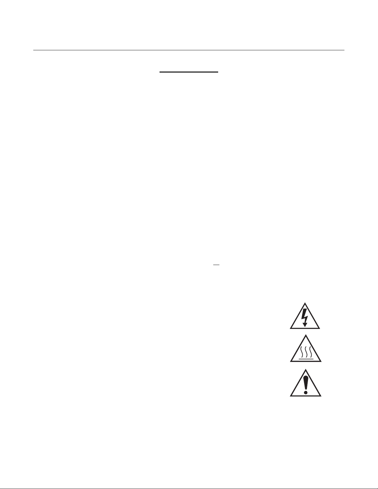
7. Where equipment or covers are marked with the symbol to the right, hazard-
ous voltages are likely to be present beneath. These covers should only be
removed when power is removed from the equipment — and then only by
trained service personnel.
8. Where equipment or covers are marked with the symbol to the right, there is a
danger from hot surfaces beneath. These covers should only be removed by
trained service personnel when power is removed from the equipment. Certain surfaces may remain hot to the touch.
9. Where equipment or covers are marked with the symbol to the right, refer to
the Operator Manual for instructions.
10. All graphical symbols used in this product are from one or more of the follow-
ing standards: EN61010-1, IEC417, and ISO3864.
P-2 Rosemount Analytical Inc. A Division of Emerson Process Management
Instruction Manual
1
IB-106-340AC Rev. 1.1
SPS 4000
SECTION 1
DESCRIPTION AND SPECIFICATIONS
NOTE
The SPS 4000 Single Probe Autocalibration Sequencer operates exactly the same with either
the Oxymitter 4000 Oxygen Transmitter or the Oxymitter 5000 Oxygen Transmitter with
OUNDATION
F
instruction bulletin also include the Oxymitter 5000. When referred to an instruction bulletin
for more information, reference IB-106-340 for the Oxymitter 4000 and IB-106-340-FB for the
Oxymitter 5000.
fieldbus Communications. Any references to the Oxymitter 4000 throughout this
April 2001
1-1 COMPONENT CHECKLIST
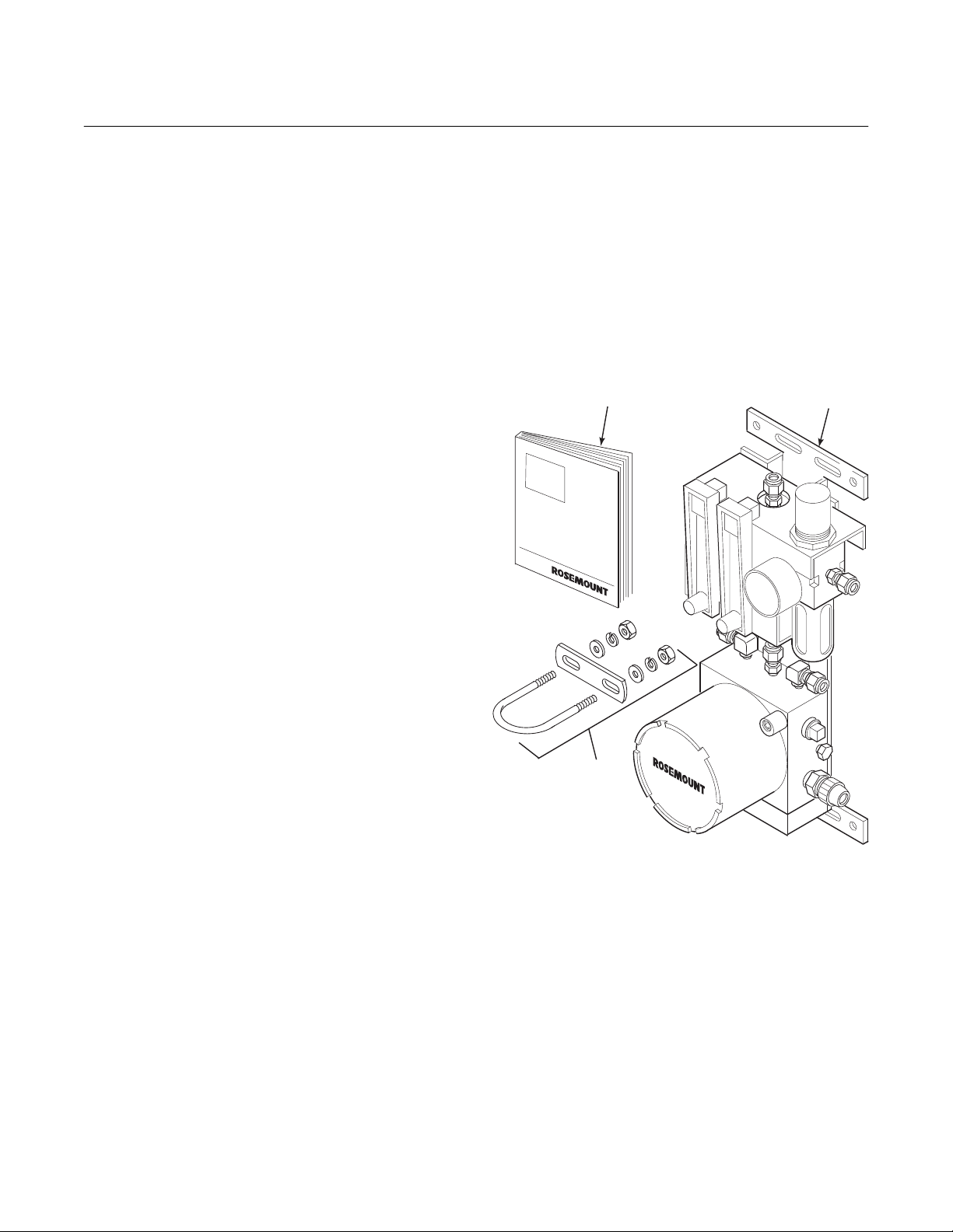
A typical SPS 4000 Single Probe Autocalibration Sequencer should contain the items shown
in Figure 1-1. Record the part number, serial
number, and order number for the SPS 4000 on
the first page of this manual.
Also, use the product matrix in Table 1-1 to
compare your order number against your unit.
The first part of the matrix defines the model.
The last part defines the various options and
features of the sequencer. Ensure the features
and options specified by your order number are
on or included with the unit.
1-2 OVERVIEW
The SPS 4000 provides the capability of performing automatic, timed or on demand, calibrations of a single Oxymitter 4000 without sending
a technician to the probe site.
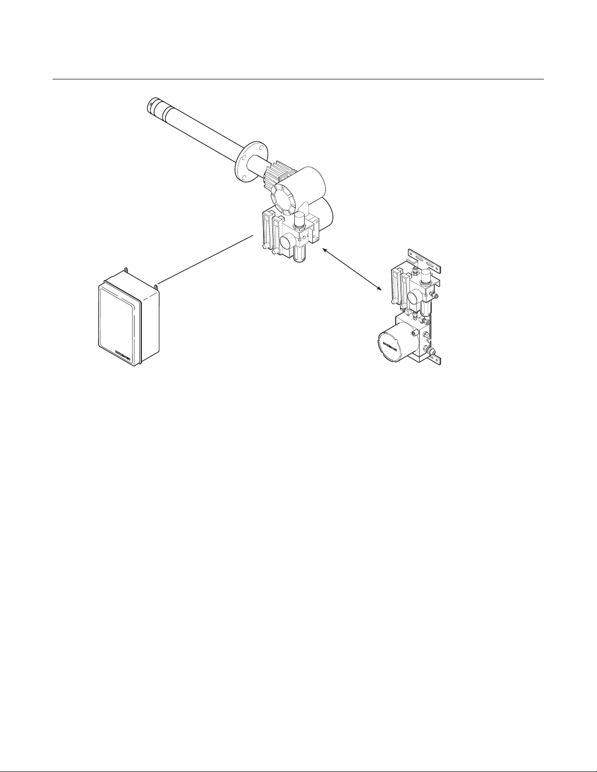
The SPS 4000 can be mounted either directly to
an In situ Oxymitter 4000 or at a remote location
if space is limited. See Figure 1-2. However, this
instruction bulletin only covers remote mounted
sequencers. For information regarding integrally
mounted sequencers, refer to the Oxymitter
4000 Oxygen Transmitter Instruction Bulletin.
For information on equipping your existing
Oxymitter 4000 with an integrally mounted SPS
4000, contact Rosemount.
1
3
1. Instruction Bulletin
2. SPS 4000 (shown with optional reference air components)
3. Optional Mounting Hardware (for pipe mounting)
Figure 1-1. Typical SPS 4000 Package
2
26010001
Rosemount Analytical Inc. A Division of Emerson Process Management Description and Specifications 1-1

Instruction Manual
IB-106-340AC Rev. 1.1
April 2001
Table 1-1. Product Matrix
SPS 4000 B Autocalibration System for Oxymitter 4000 or Oxymitter 5000. Mounted separate from the probe.
SPS 4000 Autocalibration System - Instruction Bulletin
Code Oxygen Analyzer System
20 Used with Oxymitter 4000 or Oxymitter 5000 system (remote mounted only)
SPS 4000
Code Reference Air
1 No reference air required
2 Reference air provided
Code Fittings and Tubing
1 Brass Fittings, Teflon Tubing
2 Stainless Steel Fittings and Tubing
Code Electrical Classification
10 NEMA 4X
20 Hazardous Area Classifications - Cenelec EExd IIB + H2
30 Hazardous Area Classifications (Class I, Div. I, Group B,C,D) - PENDING
SPS 4000 B 20 1 1 10 Example
Notes:
(1)
Reference air is recommended with 9 ft (2.74 m) and 12 ft (3.66 m) long probes. Reference air is also recommended when ambient air may
not contain the normal 20.95% O
unit nearby with leaks.
2)
Customer to pipe from remote SPS 4000 to probe.
3)
Hazardous area classifications require stainless steel fittings and tubing.
, such as when the probe is mounted into a positive pressure duct with leaks or where there is a process
2
(1)
(2)
(3)
(3)
Table 1-2. Calibration Components
Part Number Description
1A99119G01 Two disposable calibration gas bottles—0.4% and 8%
O
, balance nitrogen—550 liters each, includes bottle
2
rack*
1A99119G02 Two flow regulators for calibration gas bottles
*Calibration gas bottles cannot be shipped via airfreight.
When the bottles are used with “CALIBRATION RECOMMENDED” features,
the bottles should provide 2 to 3 years of calibrations in normal service.
1-2 Description and Specifications Rosemount Analytical Inc. A Division of Emerson Process Management
SPS 4000
1
Instruction Manual
IB-106-340AC Rev. 1.1
April 2001
OXYMITTER 4000
INTEGRAL OR
REMOTE
INTEGRALLY
MOUNTED SPS 4000
SINGLE PROBE
AUTOCALIBRATION
SEQUENCER
(1 PROBE)
REFER TO IB-106-340
INTELLIGENT MULTIPROBE
IMPS 4000
TEST GAS SEQUENCER
FOR USE WITH OXYMITTER 4000
(1 TO 4 PROBES)
Figure 1-2. Autocalibration System Installation Options
In addition to the SPS 4000, multiprobe sequencers are also available as shown in Figure
1-2. Rosemount has offered multiprobe autocalibration sequencer systems for many years.
These autocalibration systems are most cost
REMOTE MOUNTED SPS 4000
SINGLE PROBE
AUTOCALIBRATION SEQUENCER
FOR USE WITH OXYMITTER 4000
(EXPLO VERSIONS MUST BE REMOTE MOUNTED)
(1 PROBE)
26010003
effective for boilers and other combustion processes that utilize many probes. Users with only
one probe per combustion process can now
take advantage of Rosemount’s autocalibration
capability by utilizing the SPS 4000.
Rosemount Analytical Inc. A Division of Emerson Process Management Description and Specifications 1-3

Instruction Manual
IB-106-340AC Rev. 1.1
April 2001
1-3 SPECIFICATIONS
Mounting ............................................................. Integral to Oxymitter 4000
Remote from Oxymitter 4000
Materials of Construction
Manifold/electronics enclosure ................. Aluminum
Mounting brackets .................................... 316 stainless steel (SS)
Pneumatic fittings ..................................... 1/8 in. brass NPT (SS optional)
Pneumatic tubing ...................................... 1/4 in. Teflon (SS optional)
Assembly hardware .................................. Galvanized and stainless steel
Humidity range .................................................... 100% relative humidity
Ambient temperature range ................................ -40° to 149°F (-40° to 65°C)
Electrical classification ........................................ NEMA 4X (IP56)
Explosion-proof option (both pending) ................ CENELEC EExd IIB + H2
(Class 1, Div. 1, Group B, C, D)
SPS 4000
Electrical feedthroughs........................................ 1/2 in. NPT
Input power.......................................................... 90 to 250VAC, 50/60Hz
Power consumption............................................. 5VA maximum
External electrical noise ...................................... EN 50 082-2, includes 4KV electrostatic discharge
Handshake signal to/from
Oxymitter 4000 (self-powered) ................. 5V (5mA maximum)
Cal initiate contact input from control room......... 5 to 30VDC, Form A (SPST)
(one “In-Cal”, one “Cal Failed”)
Cabling distance between SPS 4000 and
Oxymitter 4000 ......................................... Maximum 1000 ft (303 m)
Piping distance between SPS 4000 and
Oxymitter 4000 ......................................... Maximum 300 ft (91 m)
Approximate shipping weight .............................. 10 lbs (4.5 kg)
Fisher-Rosemount has satisfied all obligations coming from the European legislation to harmonize
the product requirements in Europe.
1-4 Description and Specifications Rosemount Analytical Inc. A Division of Emerson Process Management

SPS 4000
1
Instruction Manual
IB-106-340AC Rev. 1.1
April 2001
1-4 PHYSICAL DESCRIPTION
The main components of the SPS 4000 are described in the following paragraphs and illustrated in Figure 1-3.
a. Manifold
The manifold provides a mounting platform
for the circuit board(s) and terminations and
contains the electrical feedthroughs. Also,
calibration gases are piped into and sequenced through solenoids mounted on the
manifold.
b. Calibration Gas Solenoids
The calibration gas solenoids sequence the
calibration gases. One solenoid controls
calibration gas 1 (high calibration gas), and
the other controls calibration gas 2 (low
calibration gas). The solenoids activate and
deactivate to allow the calibration gases to
flow between the sequencer and Oxymitter
4000.
c. Pressure Switch
The pressure switch detects if the pressure
of a calibration gas is low, which can be
caused by an empty gas bottle, a disconnected gas line, etc. Calibration is prohibited when calibration gas pressure is low.
d. Power Supply Board
This board converts the incoming line voltage from AC to DC for use by the solenoids,
terminations, and the programmable logic
device. The power supply board also has a
5 A, 250 V, slow blow fuse.
REFERENCE AIR
PRESSURE REGULATOR
(OPTIONAL)
NOTE:
CALIBRATION GAS
FLOWMETER
MANIFOLD COVER IS
REMOVED TO SHOW
INTERNAL COMPONENTS.
ALSO, BOARD COMPONENTS
ARE NOT SHOWN FOR CLARITY.
PRESSURE
SWITCH
CALIBRATION GAS 1
(HIGH CAL GAS)
SOLENOID
INTERFACE
BOARD
Figure 1-3. SPS 4000 Components
REFERENCE AIR
FLOWMETER
(OPTIONAL)
MANIFOLD
CALIBRATION GAS 2
(LOW CAL GAS)
SOLENOID
POWER
SUPPLY BOARD
TERMINAL COVER
26010002
Rosemount Analytical Inc. A Division of Emerson Process Management Description and Specifications 1-5
Loading...