


Model SCS 921A
Reagent-Based Chlorine System
Instruction Manual
PN 51-SCS921A/rev.A
November 2003
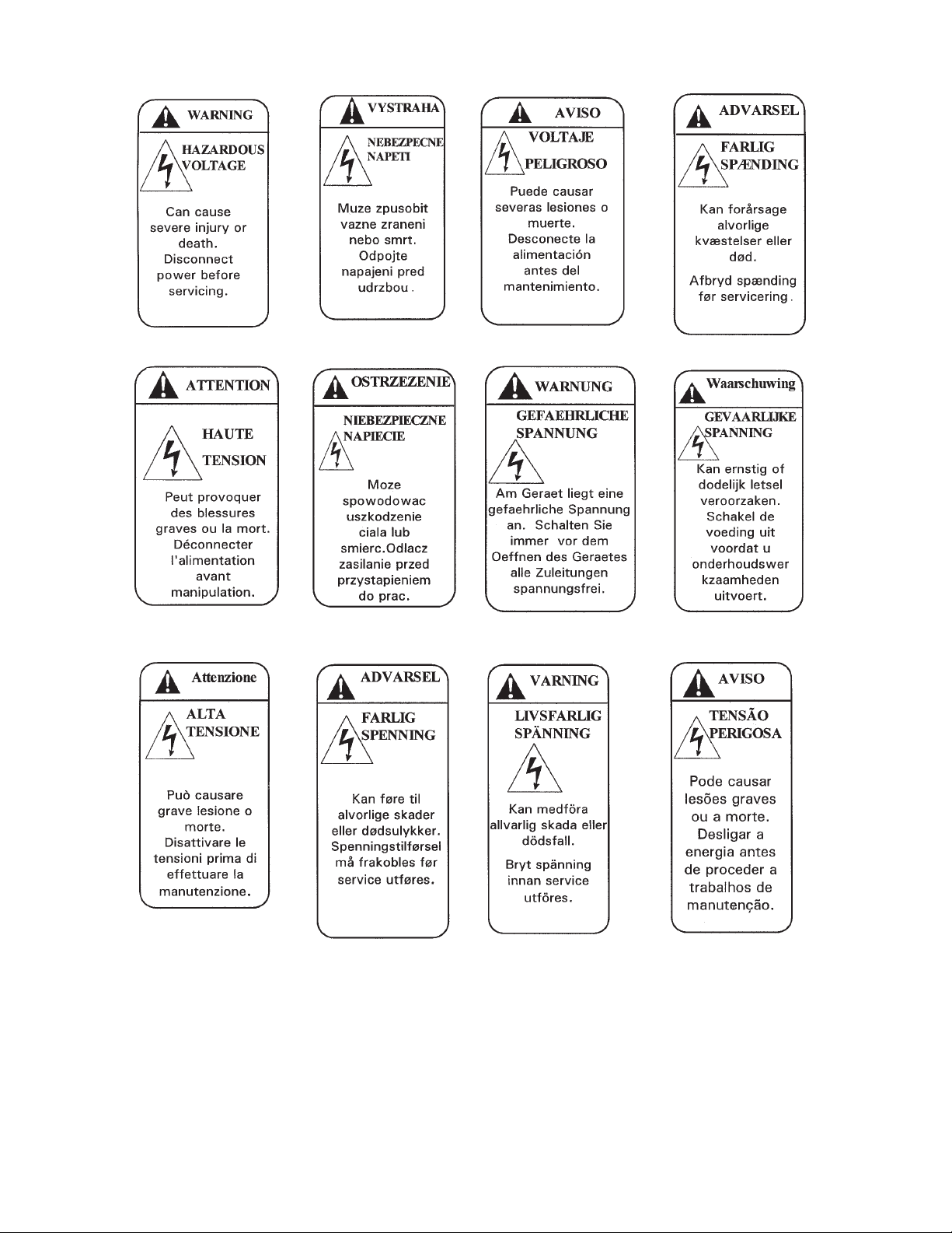
WARNING
ELECTRICAL SHOCK HAZARD
Making cable connections to and servicing
this instrument require access to shock hazard level voltages which can cause death or
serious injury.
Be sure to disconnect all hazardous voltage
before opening the enclosure.
Relay contacts made to separate power
sources must be disconnected before servicing.
Electrical installation must be in accordance
with the National Electrical Code
(ANSI/NFPA-70) and/or any other applicable
national or local codes.
Unused cable conduit entries must be
securely sealed by non-flammable closures
to provide enclosure integrity in compliance
with personal safety and environmental protection requirements.
The unused conduit openings need to be
sealed with NEMA 4X or IP65 conduit plugs
to maintain the ingress protection rating
(IP65).
For safety and proper performance this
instrument must be connected to a properly
grounded three-wire power source.
Proper relay use and configuration is the
responsibility of the user.
No external connection to the instrument of
more than 69VDC or 43V peak allowed with
the exception of power and relay terminals.
Any violation will impair the safety protection
provided
Do not operate this instrument without front
cover secured. Refer installation, operation
and servicing to qualified personnel.
ESSENTIAL INSTRUCTIONS
READ THIS PAGE BEFORE
PROCEEDING!
Rosemount Analytical designs, manufactures, and tests its
products to meet many national and international standards. Because these instruments are sophisticated technical products, you must properly install, use, and maintain
them to ensure they continue to operate within their normal
specifications. The following instructions must be adhered
to and integrated into your safety program when installing,
using, and maintaining Rosemount Analytical products.
Failure to follow the proper instructions may cause any one
of the following situations to occur: Loss of life; personal
injury; property damage; damage to this instrument; and
warranty invalidation.
• Read all instructions prior to installing, operating, and
servicing the product. If this Instruction Manual is not the
correct manual, telephone 1-800-654-7768 and the
requested manual will be provided. Save this Instruction
Manual for future reference.
• If you do not understand any of the instructions, contact
your Rosemount representative for clarification.
• Follow all warnings, cautions, and instructions marked on
and supplied with the product.
• Inform and educate your personnel in the proper installation, operation, and maintenance of the product.
• Install your equipment as specified in the Installation
Instructions of the appropriate Instruction Manual and
per applicable local and national codes. Connect all
products to the proper electrical and pressure sources.
• T o ensure proper performance, use qualified personnel to
install, operate, update, program, and maintain the product.
• When replacement parts are required, ensure that qualified people use replacement parts specified by
Rosemount. Unauthorized parts and procedures can
affect the product’s performance and place the safe operation of your process at risk. Look alike substitutions may
result in fire, electrical hazards, or improper operation.
• Ensure that all equipment doors are closed and protective covers are in place, except when maintenance is
being performed by qualified persons, to prevent electrical shock and personal injury.
WARNING
This product is not intended for use in the light industrial, residential or commercial environment, per the
instrument’s certification to EN50081-2.
Emerson Process Management
Rosemount Analytical Inc.
2400 Barranca Parkway
Irvine, CA 92606 USA
Tel: (949) 757-8500
Fax: (949) 474-7250
http://www.raihome.com
© Rosemount Analytical Inc. 2003
CAUTION
SENSOR/PROCESS
APPLICA
TION COMPATIBILITY
Wetted materials may not be compatible with process composition and
operating conditions. Application
compatibility is entirely the responsibility of the user.
DANGER
HAZARDOUS
AREA INSTALLATION
Installations near flammable liquids or in hazardous area locations must be carefully evaluated by qualified on site safety personnel.
This device is not Intrinsically Safe or
Explosion Proof.
To secure and maintain an intrinsically safe
installation, the certified safety barrier,
transmitter, and sensor combination must
be used. The installation system must comply with the governing approval agency (FM,
CSA or BASEEFA/CENELEC) hazardous
area classification requirements. Consult
your analyzer/transmitter instruction manual
for details.
Proper installation, operation and servicing
of this device in a Hazardous Area Installation is entirely the responsibility of the user.
About This Document
This manual contains instructions for installation and operation of the Model SCS921A
Reagent-Based Chlorine System.
The following list provides notes concerning all revisions of this document.
Rev. Level Date Notes
A 11/03 This is the initial release of the product manual. The manual
has been reformatted to reflect the Emerson documentation
style and updated to reflect any changes in the product offering.

MODEL SCS 921A TABLE OF CONTENTS
MODEL SCS 921A
REAGENT-BASED CHLORINE SYSTEM
TABLE OF CONTENTS
Section Title Page
1.0 DESCRIPTION AND SPECIFICATIONS.................................................... 1
Specifications.............................................................................................. 1
Ordering Information................................................................................... 2
2.0 INSTALLATION.......................................................................................... 4
Unpacking and Inspection .......................................................................... 4
Installation................................................................................................... 4
3.0 PRINCIPLES OF OPERATION.................................................................. 6
4.0 START-UP.................................................................................................. 7
Install the Sensor........................................................................................ 7
Install the Sample and Drain Lines............................................................. 7
Connect the Sample Conditioning Cabinet to a Power Source.................. 7
Start Sample Flow....................................................................................... 7
Zero the Sensor.......................................................................................... 8
Prepare and Install the Reagent................................................................. 8
Begin Operation.......................................................................................... 8
5.0 CALIBRATION ........................................................................................... 9
6.0 MAINTENANCE AND TROUBLESHOOTING........................................... 10
Inspection ................................................................................................... 10
Sample Conditioning Reagent.................................................................... 10
Peristaltic Pump.......................................................................................... 10
Sensor ........................................................................................................ 10
Reagent Flow Check Procedure................................................................. 11
Cleaning the Sample Conditioning System ................................................ 11
Troubleshooting.......................................................................................... 12
i

MODEL SCS 921A TABLE OF CONTENTS
TABLE OF CONTENTS CONT'D.
LIST OF FIGURES
Figure No. Title Page
2-1 Recommended Arrangement of Analyzer & Sample Conditioning Cabinet. 4
2-2 Dimensions of SCS 921A Case.................................................................. 5
3-1 Schematic of Sample Conditioning System and Analyzer.......................... 6
3-2 Sample Conditioning System...................................................................... 6
ii
 Loading...