

Manual: Rosemount™ DP Level Transmitters and 1199 Diaphragm Seal Systems
Table of contents
 Loading...
Rosemount Manual: Rosemount™ DP Level Transmitters and 1199 Diaphragm Seal Systems Manuals & Guides

Reference Manual
00809-0100-4002, Rev FA
Rosemount™ DP Level Transmitters and
Diaphragm Seal Systems
April 2022

Safety Messages
NOTICE
For technical assistance. contacts are listed below:
Customer Central
Technical support, quoting, and order related questions.
United States:
Asia Pacific:
Europe/Middle East/Africa:
North American Response Center
Equipment service needs
1-800-654-7768 (24 hours - includes Canada)
Outside of these areas, contact your local Emerson representative.
1-800-999-9307 (7:00 a.m. to 7:00 p.m. CST)
65 777 8211
49 (8153) 9390
WARNING
Follow instructions
Failure to follow these installation guidelines could result in death or serious injury.
Ensure only qualified personnel perform the installation.
Explosion
Explosions could result in death or serious injury.
Do not remove the transmitter cover in explosive atmospheres when the circuit is live.
Before connecting a handheld communicator in an explosive atmosphere, ensure that the instruments in the loop are installed in
accordance with intrinsically safe or non-incendive field wiring practices.
Both transmitter covers must be fully engaged to meet explosion-proof requirements.
Verify the operating atmosphere of the transmitter is consistent with the appropriate hazardous locations certifications.
Electical hazard
Electrical shock could cause death or serious injury.
If the sensor is installed in a high-voltage environment and a fault or installation error occurs, high voltage may be present on
transmitter leads and terminals.
Use extreme caution when making contact with the leads and terminals.
Process leaks
Process leaks could result in death or serious injury.
Install and tighten all four flange bolts before applying pressure.
Do not attempt to loosen or remove flange bolts while the transmitter is in service.
Replacement equipment or spare parts not approved by Emerson for use as spare parts could reduce the pressure retaining
capabilities of the transmitter and may render the instrument dangerous.
Use only bolts supplied or sold by Emerson as spare parts.
Manifold installation
Improper assembly of manifolds to traditional flange can damage sensor module.
For safe assembly of manifold to traditional flange, bolts must break back plane of flange web (i.e., bolt hole) but must not contact
sensor module housing.
2

WARNING
Sensor module and electronics housing
Sensor module and electronics housing must have equivalent approval labeling in order to maintain hazardous location approvals.
When upgrading, verify sensor module and electronics housing certifications are equivalent. Differences in temperature class
ratings may exist, in which case the complete assembly takes the lowest of the individual component temperature classes (for
example, a T4/T5 rated electronics housing assembled to a T4 rated sensor module is a T4 rated transmitter.)
Physical access
Unauthorized personnel may potentially cause significant damage to and/or misconfiguration of end users’ equipment. This could
be intentional or unintentional and needs to be protected against.
Physical security is an important part of any security program and fundamental to protecting your system. Restrict physical access
by unauthorized personnel to protect end users’ assets. This is true for all systems used within the facility.
CAUTION
The products described in this document are NOT designed for nuclear-qualified applications.
Using non-nuclear qualified products in applications that require nuclear-qualified hardware or products may cause inaccurate
readings.
Individuals who handle products exposed to a hazardous substance can avoid injury if they are informed of and understand the
hazard. If the product being returned was exposed to a hazardous substance as defined by OSHA, a copy of the required Material
Safety Data Sheet (MSDS) for each hazardous substance identified must be included with the returned goods.
3

4

Reference Manual Contents
00809-0100-4002 April 2022
Contents
Chapter 1 Introduction.............................................................................................................. 7
1.1 Using this manual........................................................................................................................ 7
1.2 Product recycling/disposal...........................................................................................................7
Chapter 2 Remote Seal Systems................................................................................................. 9
2.1 DP Level and remote seal system measurement.......................................................................... 9
2.2 Terminology of system components............................................................................................9
2.3 Seal system performance...........................................................................................................10
2.4 Balanced vs. Tuned-System assemblies......................................................................................12
2.5 Specifying the right solution for vacuum applications................................................................14
2.6 Diaphragm weld types...............................................................................................................15
2.7 Differences between electronic remote sensors and capillary systems.......................................17
2.8 Instrument Toolkit: seal ordering and application process......................................................... 17
2.9 Rosemount Thermal Range Expander: proper use and applications........................................... 18
2.10 Thermal optimizer: proper use and applications...................................................................... 20
Chapter 3 Installation...............................................................................................................23
3.1 Seal handling and installation.................................................................................................... 23
3.2 Gaskets......................................................................................................................................25
3.3 Tagging..................................................................................................................................... 26
3.4 Torque sequence....................................................................................................................... 27
3.5 FFW flush flanged seal................................................................................................................28
3.6 Offline (RFW) remote flanged seal............................................................................................. 31
3.7 EFW extended flanged seal........................................................................................................ 35
3.8 PFW pancake seal...................................................................................................................... 36
3.9 FCW flush flanged seal—ring type joint (RTJ) gasket surface....................................................... 39
3.10 RCW remote flanged seal - ring type joint (RTJ) gasket surface.................................................41
3.11 FUW flush flanged groove type seals........................................................................................43
3.12 FVW flush flanged tongue type seals........................................................................................45
3.13 RTW remote threaded type seals............................................................................................. 47
3.14 HTS male threaded seal........................................................................................................... 50
3.15 SCW hygienic Tri-Clover Tri Clamp seals...................................................................................51
3.16 SSW hygienic tank spud seal.................................................................................................... 54
3.17 STW hygienic thin wall tank spud seal......................................................................................58
3.18 EES hygienic flanged tank spud extended seal..........................................................................59
3.19 VCS Tri Clamp in-line seal.........................................................................................................60
3.20 SVS VARIVENT® compatible hygienic connection seal..............................................................62
3.21 SHP hygienic Cherry-Burrell® “I” line seal................................................................................. 63
Rosemount DP Level 5

Contents Reference Manual
April 2022 00809-0100-4002
3.22 SLS dairy process connection–female thread seal per DIN 11851.............................................64
3.23 WSP saddle seal....................................................................................................................... 65
3.24 UCP union connection pipe mount seal....................................................................................67
3.25 PMW paper mill sleeve seal......................................................................................................70
3.26 CTW chemical tee seal.............................................................................................................72
3.27 TFS wafer style In-line seal........................................................................................................73
3.28 WFW flow-thru flanged seal.....................................................................................................75
Chapter 4 Configuration...........................................................................................................77
4.1 Calculating range points............................................................................................................ 77
4.2 DP Level transmitter installation best practices..........................................................................84
Chapter 5 Fill Fluids..................................................................................................................91
5.1 Quality.......................................................................................................................................91
5.2 Fill fluid selection....................................................................................................................... 91
5.3 Fill fluid vapor pressure curves................................................................................................... 92
Chapter 6 Maintenance and Troubleshooting...........................................................................95
6.1 Cleaning.................................................................................................................................... 95
6.2 Troubleshooting........................................................................................................................95
6.3 Return of materials.................................................................................................................... 97
6.4 Service support..........................................................................................................................97
Chapter 7 Reference data......................................................................................................... 99
7.1 Product certifications.................................................................................................................99
7.2 Ordering information, specifications, and drawings...................................................................99
7.3 Spare parts................................................................................................................................ 99
6 Emerson.com/Rosemount

Reference Manual Introduction
00809-0100-4002 April 2022
1 Introduction
1.1 Using this manual
This manual is designed to assist in installing, operating, and maintaining the Rosemount
Diaphragm Seal Systems for Pressure Transmitters and diaphragm seal systems that are
part of Rosemount DP Level Transmitters including the Rosemount 3051SAL, Rosemount
3051L and Rosemount 2051L. The manual contains information about the seal system
assemblies that are not covered in the corresponding transmitter manuals. For
information regarding transmitter configuration, operation, and maintenance, reference
the appropriate transmitter manual.
The information is organized into the following categories:
• Remote Seal Systems provides an overview of Remote Seal Systems.
• Installation contains mechanical and electrical installation instructions.
• Configuration outlines how to range a DP Level Remote Seal System.
• Fill Fluids describes the offering of fill fluids available with Remote Seal Systems.
• Maintenance and Troubleshooting provides techniques for cleaning and maintaining
the system as well as addressing the most common operating problems.
• Reference data provides resources for product certifications, ordering information,
specifications, drawings, and spare parts.
See Rosemount DP Level Transmitters and 1199 Seal Systems Product Data Sheet or 1299
Seal System Product Data Sheet for more detailed information on specific Rosemount
Remote Seals.
A remote seal system consists of a pressure transmitter, a remote diaphragm, and either a
direct mount or capillary style connection filled with a secondary fill fluid.
Rosemount uses both the 1199 and 1299 models for specifying remote seals. This manual
includes information for both.
1.2 Product recycling/disposal
Recycling of equipment and packaging should be taken into consideration and disposed of
in accordance with local and national legislation/regulations.
Rosemount DP Level 7

Introduction Reference Manual
April 2022 00809-0100-4002
8 Emerson.com/Rosemount

A
B
C D
E
B
C
F
Reference Manual Remote Seal Systems
00809-0100-4002 April 2022
2 Remote Seal Systems
2.1 DP Level and remote seal system measurement
DP Level is a reliable measurement solution for measuring level, density, interface, or mass
of a process media inside a tank.
Remote seal system measurement is unaffected by agitation, foam, or internal obstacles.
Remote diaphragm seals extend limitations due to process conditions such as high and
low temperatures, corrosive processes, viscous mediums, and hygienic applications.
2.2 Terminology of system components
Figure 2-1 lists the basic components for seal assemblies.
Figure 2-1: Components on a Two- and Single-Seal Assembly
Two-seal assembly
A. Pressure, differential pressure, or multivariable transmitter
B. Process flange
C. Remote diaphragm
D. Capillary
E. Flushing ring (optional)
F. Direct mount
Single-seal assembly
Rosemount DP Level 9
A
B
C
D
Remote Seal Systems Reference Manual
April 2022 00809-0100-4002
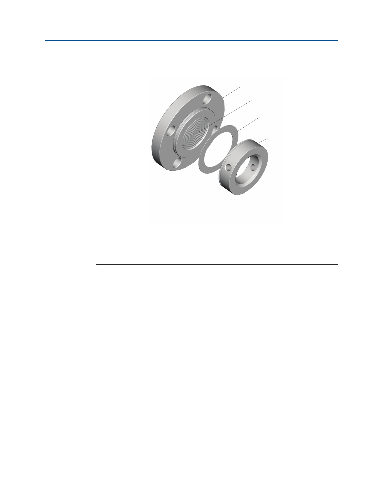
Figure 2-2: Flushed Flanged (FFW) Seal and Components
A. Process flange
B. Diaphragm
C. Gasket
D. Flushing ring (optional)
2.3 Seal system performance
2.3.1 Volume temperature effects (process temperature effects)
Fill fluids expand or contract with temperature changes, creating a volume change that is
absorbed by the diaphragm seal and is seen as back pressure at the transmitter. This back
pressure creates a shift in the transmitter reading. For symmetrical or balanced systems,
this error is usually minimal due to the back pressure being equal on both sides. However,
head temperature effect is still present.
Note
Other factors that affect seal temperature effect include diaphragm thickness, seal type
and size, capillary length, and inner diameter.
Figure 2-3 shows how diaphragm size can affect the measurement reading at the
transmitter. For smaller seal sizes, such as the 1½-in. size, the amount of back pressure on
the transmitter causes an additional 12.1 inH2O (307 mmH2O)error. Moving to the 2-in.
size gives 1.7 inH2O (43 mmH2O)and the largest 3-in. size shown only has 0.5 inH2O (13
mmH2O)error. Using a larger diaphragm can drastically improve performance and
provides a more stable reading.
10 Emerson.com/Rosemount

Reference Manual Remote Seal Systems
00809-0100-4002 April 2022
Note
Calculations done in Instrument Toolkit™ with Silicone 200 fill fluid with Rosemount 3051
Transmitter.
Figure 2-3: Back Pressure on Diaphragm Causing Error
2.3.2
2.3.3
Note
Diaphragm temperature effects decrease as seal size increases.
Density temperature effects (head temperature effects)
Density temperature effect is due to the change in specific gravity of the fill fluid caused by
a change in ambient temperature. When installed, the weight of the fill fluid will produce
an initial pressure read by the transmitter, equaling the height between the high and low
connection taps multiplied by the fill fluid's specific gravity. As ambient temperature
changes, the fill fluid specific gravity will change causing the weight of the fill fluid to
change, thus changing the pressure read by the transmitter. Density effect will be seen in
both
Tuned-System™ Assemblies and Balanced System Assemblies and will have the same
impact on the transmitter regardless of where the transmitter is mounted.
System time response and performance
The time response of a system is based on the type of transmitter, its sensor range, the
length and inner diameter (ID) of the capillary, and the viscosity of the fill fluid (which is
directly affected by the process and ambient temperatures). These factors all play a role in
the overall performance of any seal system. The relationship between system time
response and temperature error is illustrated in Figure 2-4. It can be seen that changing
the capillary ID has an inverse affect between the time response and temperature effect of
a capillary system. As the capillary ID is increased, the time response of the system
decreases while the temperature effect increases.
Rosemount DP Level 11

Remote Seal Systems Reference Manual
April 2022 00809-0100-4002
Figure 2-4: Response Time vs. Total Performance Example
Note
Calculations conducted using Instrument Toolkit.
Parameters: Silicone 200 fill fluid, Rosemount 3051CD2 Transmitter, 15 ft. capillary
length, 2-in. FFW Seal, and calibrated at 25 °C.
2.4 Balanced vs. Tuned-System assemblies
A balanced remote seal system is a symmetrical system that utilizes equal seals and
capillary length on the high and low pressure sides of the transmitter. Since the capillary
lengths are the same, each side ideally has the same amount of fill fluid, minimizing or
completely eliminating the seal temperature effect due to equal pressure on both sides of
the transmitter diaphragm. The balanced systems are still affected by the head pressure as
shown in Figure 2-5.
12 Emerson.com/Rosemount
Reference Manual Remote Seal Systems
00809-0100-4002 April 2022
Figure 2-5: Balanced System
+3.6 inH2O
(9.0 mbar)
No error
(Cancels out)
+3.6 inH2O
(9.0 mbar)
Head temperature
effect
Seal temperature
effect
Total temperature
effect on system
Note
Temperature effects were calculated in Instrument Toolkit using a 2-in. (DN 50) FFW seal,
Silicone 200, 10 ft. (3 m) between the taps, over a 50 °F (28 °C) temperature change.
Tuned-Systems assemblies are asymmetrical remote seal systems with one seal directly
mounted to the high side of the differential pressure transmitter, and the other side
connected to a seal via capillary. Another possible Tuned-System assembly is any remote
seal system with unequal lengths of capillary or two different remote seals on the high and
low pressure connections. Due to the unequal lengths of capillary, there are seal
temperature effects. However, this seal temperature effect counters the head pressure
from the oil-filled capillary and reduces total temperature effects on the entire system.
Figure 2-6: Tuned-System Assembly
Head temperature
effect
Seal temperature
effect
Total temperature
effect on system
+3.6 inH2O
(9.0 mbar)
-1.7 inH2O
(4.2 mbar)
+1.9 inH2O
(4.7 mbar)
Note
Temperature effects were calculated in Instrument Toolkit using a 2-in. (DN 50) FFW seal,
Silicone 200, 10 ft. (3 m) between the taps, over a 50 °F (28 °C) temperature change.
Rosemount DP Level 13

Remote Seal Systems Reference Manual
April 2022 00809-0100-4002
2.5 Specifying the right solution for vacuum applications
2.5.1 Vacuum application overview
When a vessel is operating in a vacuum (negative gauge pressure), it is important to
specify the correct transmitter remote seal system to measure level accurately and
reliably. Failure to do so can result in output drift or complete system failure. The
combination of high process temperature and vacuum process pressure conditions
creates additional requirements when specifying the transmitter remote seal system.
2.5.2 Vacuum applications
There are three primary transmitter-seal system components necessary to successfully
specify vacuum application solutions:
• Seal system construction
2.5.3
2.5.4
• Fill fluid selection
• Transmitter mounting position
Seal system construction for vacuum applications
Emerson offers welded-repairable or all-welded vacuum system construction styles on
diaphragm seal assembles.
The all-welded vacuum construction was designed specifically for vacuum applications. In
this construction, the sensor module gaskets are removed and a disk is welded over the
sensor isolators. This eliminates the possibility of air being drawn into the seal system in
deep vacuum conditions. This premium design is strongly suggested for vacuum pressures
below 6 psia (310 mmHga).
Transmitter mounting position
Mounting the pressure transmitter at or below the bottom vessel tap is an important
factor to ensure a stable measurement with vacuum applications. The static pressure limit
for a differential pressure transmitter is 0.5 psia (25 mmHgA), which ensures the
transmitter sensor module fill fluid remains within the liquid phase of the vapor pressure
curve.
If the vessel static limit is below 0.5 psia, mounting the transmitter below the bottom tap
provides a capillary fill fluid head pressure on the module. A general rule is to always
mount the transmitter approximately 3 ft. (1 m) below the bottom tap of the vessel.
14 Emerson.com/Rosemount

A
B
A C
D
Reference Manual Remote Seal Systems
00809-0100-4002 April 2022
2.5.5 Fill fluid selection
When the process is under vacuum conditions, the fill fluid can vaporize at a lower
temperature than when it is under normal atmospheric or greater pressure. Each fill fluid
has a specific vapor-pressure curve. The vapor-pressure curve indicates the pressure and
temperature relationship where the fluid is in a liquid or a vapor state. Proper seal
operation requires the fill fluid to remain in a liquid state.
For vacuum applications, specify fluids that are specifically designed for use in these types
of applications such as Silicone 704 for vacuum applications, Silicone 705 for vacuum
applications, or UltraTherm™ 805 for vacuum applications. These fluids have been
specially processed to deliver the maximum vapor pressure curve performance possible.
For more information on Rosemount Diaphragm Seal fill fluids, reference the Rosemount
Fill Fluid Specifications Technical Note.
2.6 Diaphragm weld types
Weld-type is factory-determined as best for the seal typed specified. Pancake Flanged
(PFW) and FFW seals have ordering options that specify welding options.
2.6.1
Solid faceplate design
The solid faceplate design is used when diaphragm and upper housing material are the
same.
A. Material A
B. Upper housing
C. Diaphragm
D. TIG weld point
Rosemount DP Level 15

A
B D
C
E
F
A
B
C
D
E
Remote Seal Systems Reference Manual
April 2022 00809-0100-4002
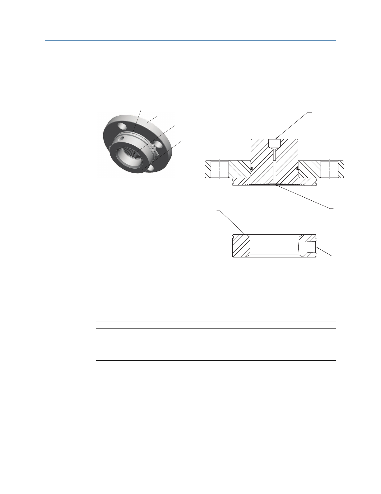
2.6.2 Seam weld design
A seam weld design is used when the upper housing material is different from the
diaphragm material. The seam welded design has a hermetic weld at the inner diameter of
the diaphragm and a TIG weld at the outer edge. The diaphragm floats on the upper
housing over the gasket surface area and could tear if a metallic gasket were used.
A. Material A
B. Material B
C. Upper housing
D. Diaphragm
E. TIG weld point
F. Seam weld point
2.6.3
Brazed design
This process uses a brazing ring where the metals are brazed to attach the diaphragm to
the upper housing. This allows the gasket surface area to solidify as it is melted to the
upper housing.
This option is used with Tantalum diaphragm when a metallic gasket is required.
A. Material A
B. Tantalum
C. Upper housing
D. Brazing ring
E. Diaphragm
16 Emerson.com/Rosemount

A
B
Reference Manual Remote Seal Systems
00809-0100-4002 April 2022
2.7 Differences between electronic remote sensors and capillary systems
Rosemount 3051S Electronic Remote Sensors (ERS™) System technology utilizes two
Rosemount 3051S Pressure Transmitters connected via an electrical wire instead of a
single pressure transmitter with remote seals and capillary tubing. As the Rosemount
3051S ERS System calculates the differential pressure between the two transmitters,
capillary tubing is not needed, and thus eliminates all head temperature affects on the
system. Seals are not required, but may still be necessary on certain applications that
include high temperature, corrosive, or viscous processes. For more information, refer to
the Rosemount 3051S Series Product Data Sheet.
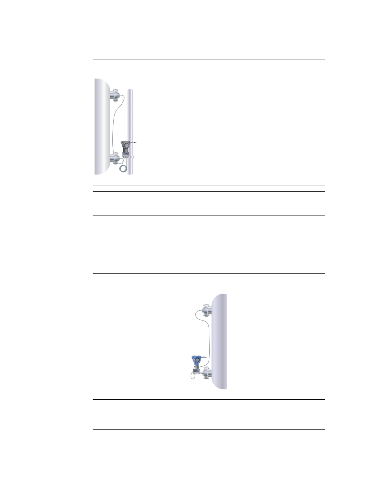
Figure 2-7: ERS vs. Capillary
Rosemount 3051S ERS
A. Non-proprietary electrical cable
B. Oil-filled capillary system
Traditional capillary system
2.8 Instrument Toolkit: seal ordering and application process
Rosemount Instrument Toolkit Software is an instrumentation specification tool that can
be used to assist in product selection. This program analyzes application and process
conditions against a configured Rosemount model number and calculates the total system
Rosemount DP Level 17
performance including expected head and seal temperature effects and system response
times.
Visit the Emerson website for information on how to obtain and use Instrument Toolkit.

Remote Seal Systems Reference Manual
April 2022 00809-0100-4002
2.9 Rosemount Thermal Range Expander: proper use and applications
Figure 2-8: Rosemount Thermal Range Expander
A. Intermediate diaphragm
B. High temperature fill fluid (viscous)
C. Ambient temperature fill fluid
The Rosemount Thermal Range Expander increases the application range where DP Level
technology can be used by expanding the ambient and process temperature ranges of the
system.
Traditional remote seal systems are filled with a single fill fluid to operate in applications
with varying ambient and process conditions. Silicone 704 and 705 are commonly used
fluids for hot process applications going above 570 °F (300 °C); these fluids must be kept
above 32 °F (0 °C) and 68 °F (20 °C), respectively, in order to properly transmit the pressure
signal to the transmitter. This can prove to be difficult for outdoor installations where
extremely cold ambient conditions cause these fill fluids to gel.
The Rosemount Thermal Range Expander is a seal system that uses two different fill fluids
to extend the operating temperature range of the system. A high temperature fill fluid,
which is next to the hot process, is kept warm enough to stay responsive. A second fill
fluid, located on the other side of the intermediate diaphragm, operates over a wide
ambient temperature range. The Rosemount Thermal Range Expander can operate in
ambient temperatures as low as –103 °F (–75 °C), and process temperatures up to 770 °F
(410 °C) and 850 °F (454 °C) design temperature
percent and eliminates the need for mechanical heat tracing.
The Rosemount Thermal Range Expander can be used with any Rosemount 3051S DP
Level configuration including Balanced Systems, Tuned-System Assembles, Electronic
Remote Sensors (ERS), or direct mounted to a transmitter.
(1)
. This improves response time up to 46
UltraTherm 805 supports maximum design temperature of 850 °F (454 °C). Design temperature rating is for non-
(1)
continuous use with a cumulative exposure time less of than 12 hours. Continuous use temperature is rated to 770 °F (410
°C).
18 Emerson.com/Rosemount

Reference Manual Remote Seal Systems
00809-0100-4002 April 2022
Figure 2-9: Rosemount Thermal Range Expander Temperature Operating Range
Rosemount DP Level 19

212 °F (100 °C)
176 °F (80°C)
140 °F (60 °C)
104 °F (40 °C)
68 °F (20 °C)
32 °F (0 °C)
-4 °F (-20 °C)
-40 °F (-40 °C)
-76 °F (-60 °C)
-112 °F (-80 °C)
212 °F (100 °C)
176 °F (80°C)
140 °F (60 °C)
104 °F (40 °C)
68 °F (20 °C)
32 °F (0 °C)
-4 °F (-20 °C)
-40 °F (-40 °C)
-76 °F (-60 °C)
-112 °F (-80 °C)
32 °F (0 °C)
122 °F (50 °C)
302 °F (150 °C)
482 °F (250 °C)
662 °F (350 °C)
842 °F (450 °C)
401 °F (205 °C)
185 °F (85 °C)
185 °F (85 °C)
599 °F (315 °C)
-58 °F (-50 °C)
91 °F (33 °C)
Process temperature °F (°C)
Ambient temperature °F (°C)
Ambient temperature °F (°C)
Process temperature °F (°C)
122 °F (50 °C)
302 °F (150 °C)
482 °F (250 °C)
662 °F (350 °C)
842 °F (450 °C)
185 °F (85 °C)
185 °F (85 °C)
-58 °F (-50 °C)
401 °F (205 °C)
-69 °F (-56 °C)
-76 °F (-60 °C)
68 °F (20 °C)
698 °F (370 °C)
68 °F (20 °C)
68 °F (20 °C)
77 °F (25 °C)
Remote Seal Systems Reference Manual
April 2022 00809-0100-4002
2.10 Thermal optimizer: proper use and applications
The thermal optimizer keeps fill fluids from gelling in cold
ambient temperatures by using high process temperatures to
heat the transmitter and capillary.
High temperature silicone fill fluid has a low temperature limit in
ambient conditions below 32 °F (0 °C). The thermal optimizer
allows direct mounting down to –94 °F (–70 °C).
Figure 2-10: Fill Fluid Temperature Limits
Thermal optimizer with Silicone 704
Thermal optimizer with Silicone 705
20 Emerson.com/Rosemount

Reference Manual Remote Seal Systems
00809-0100-4002 April 2022
2.10.1 Thermal optimizer limitations
Figure 2-10 shows the process and ambient temperature limits for the thermal optimizer
with Silicone 704 and Silicone 705 Fill Fluids respectively. The shaded areas represent the
temperature limitations; applications outside of the shaded area cannot be used with a
thermal optimizer.
For example, an application with an ambient temperature of 50 °F (10 °C) and a process
temperature of 300 °F (149 °C) is within the limits, a thermal optimizer can be used in this
application.
However, an application with an ambient temperature of 122 °F (50 °C) and a process
temperature of 464 °F (240 °C) is outside of the limits. These high temperatures would be
detrimental to the transmitter electronics.
Rosemount DP Level 21

Remote Seal Systems Reference Manual
April 2022 00809-0100-4002
22 Emerson.com/Rosemount

Reference Manual Installation
00809-0100-4002 April 2022
3 Installation
3.1 Seal handling and installation
3.1.1 Diaphragm
The remote seal diaphragm is designed to withstand pressure and wear from process, but
outside of process connection conditions, remote seals are delicate and should be handled
with care.
The protective cover should remain on the seal until the moment before installation. Try
to avoid touching the diaphragm with fingers or objects and refrain from setting the
diaphragm side of the seal down on a hard surface.
Even minor dents or scratches in the diaphragm material may impair the performance of
the seal system assembly. Care should be taken to ensure the seal diaphragm is not
dented or damaged during seal installation.
3.1.2
3.1.3
Capillary
When unpacking or handling seal system assemblies, do not lift the seal or transmitter by
gripping the capillaries. Avoid sharply bending or crimping the capillary tubing. The
minimum bending radius of the capillary tubing is 3-in. (8 cm).
Rosemount Thermal Range Expander
The Rosemount Thermal Range Expander system uses the heat from the process in order
to keep both fluids within the system functioning properly; therefore insulation is not
always required. However, it is always best practice to insulate systems to keep them
functioning with optimum performance. The Rosemount Thermal Range Expander should
never be insulated above the line marked on the seal itself.
Rosemount DP Level 23

Rosemount 3051SAL with Thermal Range Expander
Marking:
“Do Not Insulate
Above this Line”
Ok to
Insulate
Do Not
Insulate
Installation Reference Manual
April 2022 00809-0100-4002
Figure 3-1: Rosemount 3051SAL with Rosemount Thermal Range Expander Insulation
Guidelines
3.1.4 Heat tracing
When using heat or steam tracing, exercise caution if PVC coating is added onto capillary,
as PVC coating should not be exposed to temperatures above 212 °F (100 °C) to avoid the
possibility of thermal breakdown.
Best practice for heat and steam tracing is to regulate the temperature slightly above the
maximum ambient temperature for a consistent result. To avoid accuracy effects and
thermal stress, the capillary should not be partially heated.
CAUTION
NEVER attempt to disconnect the seals or capillaries from the transmitter or loosen
bolts.
Doing so will result in loss of fill fluid and will void the product warranty.
Failing to recognize incorrect materials during installation may cause process leaks, which
can result in damage to the diaphragm seal system or death and/or serious injury to
personnel. Proper wetted material is required for specific process materials.
24 Emerson.com/Rosemount

Reference Manual Installation
00809-0100-4002 April 2022
3.2 Gaskets
WARNING
When installing remote seal systems which employ a gasket or a gasket and flushing
connection ring, make sure the gasket is aligned properly on the gasket sealing surface.
The user is responsible to ensure the gasket used does not exceed the temperature limits
of the process. Failure to properly install the gasket may cause process leaks, which can
result in death or serious injury.
In addition, make sure the gasket does not press down upon the diaphragm face. Anything
pressing on the diaphragm will be read by the transmitter as pressure. A misaligned gasket
may cause a false reading.
The intermediate gasket between the seal and lower housing is supplied when the lower
housing or flushing connection is provided when ordered on an 1199. The default gaskets
are listed in Table 3-1 based on seal type. The process gasket must be supplied by the end
user. Tantalum diaphragms are not supplied with default gasket, so a gasket option must
be selected when applicable.
If a lower housing is supplied, then the following gaskets are the default gaskets for each
seal unless another gasket option is selected.
When ordering a 1299 seal system, the gasket option must be selected in the model
number, there will not be a default gasket shipped.
Table 3-1: Gasket Materials for 1199
Seal type Gaskets
Flanged seals assemblies
FFW Klingersil® C-4401
RFW Klingersil C-4401
EFW No gasket is supplied
PFW Klingersil C-4401
FCW No gasket is supplied
RCW Klingersil C-4401
FUW/FVW No gasket is supplied
Threaded seal assemblies
RTW Klingersil C-4401
HTS No gasket is supplied
Hygienic seal assemblies
(1)
SCW
No gasket is supplied
SSW Ethylene propylene O-ring
STW Ethylene propylene O-ring
EES No gasket is supplied
Rosemount DP Level 25

Installation Reference Manual
April 2022 00809-0100-4002
Table 3-1: Gasket Materials for 1199 (continued)
Seal type Gaskets
(1)
VCS
(1)
SVS
SHP No gasket is supplied
(1)
SLS
Specialty seals
WSP Klingersil C-4401
UCP Barium-Sulfate filled PTFE O-ring
CTW No gasket is supplied
TFW No gasket is supplied
WFW Klingersil C-4401
(1) Use EHEDG approved gasket for EHEDG conformity.
No gasket is supplied
No gasket is supplied
No gasket is supplied
WARNING
The end-user is responsible for choosing a gasket and ensuring the process temperature
does not exceed the temperature limits of the gasket used. Failure to properly install the
gasket may cause process leaks, which can result in death or serious injury.
3.3 Tagging
Each remote seal system is tagged in accordance with the end-user requirements. The
remote seal model number is identified on the transmitter label, shown in Figure 3-2,
Figure 3-3, and Figure 3-4.
Figure 3-2: Rosemount 3051S Sample Label
Figure 3-3: Rosemount 3051 Sample Label
26 Emerson.com/Rosemount

A
C
D
B
Reference Manual Installation
00809-0100-4002 April 2022
Figure 3-4: Rosemount 2051 Sample Label
3.3.1 Max working pressure
The maximum working pressure (MWP) of the seal system assembly is stamped on the
transmitter neck tag. This can be dependent upon the maximum pressure rating of the
seal system or transmitter upper range limit.
3.4 Torque sequence
When tightening the assembly bolts, use a cross-pattern to ensure even installation. Best
practice is to tighten 20 to 30 percent, check the gap, tighten 50 to 70 percent, check
flange gap and uniformity, and continue to tighten in the appropriate pattern until you
reach 100 percent torque value. Time permitting, wait a minimum of four hours and
repeat the torque pattern to restore any short-term creep/relaxation in the connection.
Figure 3-5: Cross-Pattern Sequence
A. 4-bolt flange
B. 8-bolt flange
C. 12-bolt flange
D. 16-bolt flange
Rosemount DP Level 27
B
C
D
A
C
E
F
D
Installation Reference Manual
April 2022 00809-0100-4002
3.5 FFW flush flanged seal
Figure 3-6: FFW Two-Piece Design (Shown with Optional Flushing Ring)
A. Alignment clamp (option code SA)
B. Process flange
C. Diaphragm
D. Flushing ring (optional)
E. Connection to transmitter
F. Flushing connection
Standard expanded
Note
Two-piece design seal assembly and process flange are separate components and can be
rotated independent of each other. Alignment clamp (A) can be ordered using option
code SA on the 1199.
28 Emerson.com/Rosemount

B
D
E
C
Reference Manual Installation
00809-0100-4002 April 2022
Figure 3-7: FFW One-Piece Design (Shown with Optional Flushing Ring)
A. Process flange
B. Diaphragm
C. Flushing ring (optional)
D. Connection to transmitter
E. Flushing connection
3.5.1
Note
Alignment clamp (option code SA) not available for FFW one-piece design.
Parts required for installation
The parts required to install the FFW flush flanged seal will be defined here. Prior to
installation, you will need the following:
• Torque wrench
• Mounting hardware (end-user-supplied)
• Gasket (end-user-supplied)
Note
Flushing rings include an Emerson-supplied gasket. If an alignment clamp is used, a Phillips
or slotted screwdriver is required for installation
Verify the gasket materials are appropriate for the application.
Inspect bolts to ensure the material is compatible with industry standards per the
application such as ASME PCC-1.
Rosemount DP Level 29

Installation Reference Manual
April 2022 00809-0100-4002
3.5.2 Installation steps
If a flushing ring is ordered and no alignment clamp is used, it is recommended that two
people install the FFW flush flanged seal to ensure proper alignment during installation.
Follow these steps to install the FFW flush flanged seal on an existing flanged process
connection:
Procedure
1. Remove the protective cover from the diaphragm of the remote seal. Use extreme
caution during installation to ensure the diaphragm is not damaged.
2. If installing a flushing ring, ensure flushing connections are sealed before
completing installation. Flushing rings may be ordered with or without, one or two
threaded flushing connections, factory supplied plugs, or drain vent valves. If no
flushing ring was purchased, proceed to Step 3. Assemble the flushing ring,
Emerson-supplied gasket, and remote seal together. If using an alignment clamp
(option code SA on the 1199) attach the flushing ring to the remote seal. Place the
alignment clamp in the machined groove on both the remote seal and the flushing
ring. Using the applicable screwdriver, tighten the screw on the clamp to hold the
flushing ring in place.
3. Insert end-user-supplied bolts in the bottom two bolt holes of the flange on the
remote seal.
4. Place the appropriate end-user-supplied gasket on the remote seal or flushing ring
and align the gasket so that it is not inside the diaphragm weld as this will induce
errors.
WARNING
Failure to properly install the gasket may cause process leaks, which can result in
death or serious injury.
5. Using the previously installed bolts, attach the remote seal and gasket to the
process connection. Secure with nuts and hand-tighten.
6. Insert end-user-supplied bolts in the top two bolt holes of the flange on the remote
seal. Secure with nuts and hand-tighten.
7. Using a torque wrench on the nut, tighten the assembly in a cross-pattern to ensure
even installation (see Torque sequence). The bolts should be torqued to the
applicable flange requirements. Required torque is a function of the gasket material
and surface treatment of the bolts and nuts which are end-user-supplied. Consider
leak checking the installation to ensure a robust connection.
30 Emerson.com/Rosemount
Loading...