

00809-0100-5800 , Rev BB
Rosemount™ CT5800 Continuous Gas
Analyzer
Reference Manual
August 2020

Preface
Published by Emerson.
All possible care has been taken in the preparation of this publication, but Emerson and its agents and distributors accept no
liability for any inaccuracies that may be found. This manual reflects the state of the product at the issue date below, but further
enhancements while in service may mean that the manual does not reflect your particular system.
Emerson reserves the right to make changes without notice both to this publication and the products which it describes.
No part of this publication may be reproduced, stored in a retrieval system, or transmitted in any form or by any means electronic,
mechanical, photocopying, recording, or otherwise without the express prior written permission of the copyright holder.
If you require additional technical assistance, request help from cascade.support@emerson.com or Emerson distribution partners.
Send general inquiries to cascade.support@emerson.com.
2

Important information
NOTICE
This section is in accordance with IEC 60079-0: 2011 Clause 30. This section must not be changed, amended, or removed.
Important
Users must read, understand, and comply with the following information before proceeding.
All users, installers, operators, and maintainers must be familiar with operating the analyzer. To install, start up, operate, maintain,
and service the analyzer in a safe manner, it is MANDATORY to read all additional instruction manuals shipped with the analyzer.
The following instruction manual(s) are available and/or referenced within this manual:
Rosemount CT5800 Quick Start Guide: 00825-0100-5800
User information
NOTICE
This section is in accordance with IEC 60079-0: 2011 Clause 30. This section must not be changed, amended, or removed.
Important
All users must read this page before proceeding!
Emerson (Rosemount) designs, manufactures, and tests its products to meet many national and international standards. The
Rosemount CT5800 is a sophisticated technical product, and to ensure it continues to operate as designed and within normal
specifications, it MUST be installed, used, and maintained correctly. The following instructions MUST be adhered to and
integrated into your safety program when installing, using, and maintaining Emerson (Rosemount) products.
• Failure to follow the proper instructions may cause:
— Loss of life
— Personal injury
— Damage to property
— Damage to this instrument
— Warranty invalidation
• Read all instructions prior to installing, operating, and servicing the product.
• If you do not understand any of the instructions, contact your Emerson (Rosemount) representative for clarification.
• Follow all warnings, cautions, and instructions marked on and supplied with the product.
• Inform and educate your personnel in the proper installation, operation, and maintenance of the product.
• Install your equipment as specified in the installation instructions of the appropriate manual and in accordance with applicable
local and national codes.
• Connect all products to the proper electrical and pressure sources.
• To ensure proper performance, use qualified personnel to install, operate, update, program, and maintain the product.
• When replacement parts are required, ensure that qualified people use replacement parts specified by Emerson (Rosemount).
• Unauthorized parts and procedures can affect the product’s performance, place the safe operation of your process at risk, and
VOID YOUR WARRANTY. Look-alike substitutions may result in fire, electrical hazards, or improper operation.
• To prevent electrical shock and personal injury, all equipment doors must be closed and protective covers in place, except
when maintenance is being performed by qualified personnel.
• The information contained in this document is subject to change without notice.
3

General safety notice/residual risk
Installation, operation, and maintenance of the analyzer must be in accordance with these instructions.
When operated as intended and all applicable safety instructions are observed, an element of risk will remain, including, but not
limited to, the following:
• Explosion protection measures may become ineffective on the occurrence of one failure (for Category 3 instruments).
• The emission of gases hazardous to health may be possible when all gas connections have been correctly made.
To avoid exposure to the dangers of residual risks, take particular care when installing, operating, maintaining, and servicing the
analyzer.
Authorized personnel
NOTICE
This section is in accordance with IEC 60079-0: 2011 Clause 30. This section must not be changed, amended, or removed.
In-depth specialist knowledge is an absolute requirement for working with and on the analyzer. Personnel installing, operating,
servicing, and maintaining the analyzer must be instructed, trained, qualified, and authorized for hazardous areas with the
operating company and the manufacturer. It is the operating company's responsibility to:
• Train staff
• Observe safety regulations
• Follow the safety instructions and procedures in the product manual
Operators must:
• Be trained
• Read and understand all relevant sections of the product manual before commencing work
• Know the safety mechanisms and regulations
WARNING
To avoid explosions, loss of life, personal injury, and damage to this equipment and on-site property, do not install, operate,
maintain, or service this instrument before reading and understanding this instruction manual and receiving appropriate training.
4

Regulations and standards
Regulations / Standards Description
2014/35/EU The Low Voltage Directive
94/9/EC (until April 19, 2016)
2014/34/EU (from April 20, 2016)
(1)
(2)
The ATEX Directive
2014/30/EU The Electromagnetic Compatibility Directive
2012/19/EU Waste Electrical and Electronic Equipment (WEEE) Directive
USA 21 CFR 1040.1 Laser products
NEC 505 National Electrical Code (issued by ANSI: American National
Standards Institute and NFPA 70: National Fire Protection
Association)
EN 6223: 2008 EMC Safety Standard
IEC 60079-10: 2002-06 Electrical apparatus for explosive gas atmospheres. Part 10:
Classification of hazardous areas
IEC 60529:1992 + A2 2013 Ingress protection
BS EN 60825-1:2007 Safety of laser products. Equipment classification and requirements
(identical to IEC 608250-1 2007).
BS EN 61010-1 2010 IEC 61010-1 2010 Safety requirements for electrical equipment for measurements,
control, and laboratory use. General requirements.
IEC 61241-10: 2004-06 Electrical apparatus for use in the presence of combustible dust.
Part 10: Classification of areas where combustible dusts are or may
be present.
BS EN 61326-1: 2013 Electrical equipment for measurement, control, and laboratory use.
EMC requirements. General requirements.
BS EN60079-0: 2012 Explosive atmospheres - Part 0: Equipment - General requirements
BES EN 60079-1: 2014 Explosive atmospheres. Equipment protection by flameproof
enclosures d
IEC 60079-0:2011 Ed 6 Explosive atmospheres - Part 0: Equipment - General requirements
IEC 60079-1:2014 Ed 7 Explosive atmospheres, Part 1: Equipment protection by flameproof
enclosures d
(1) May affect equipment tested prior to April 20, 2016, but shipped at a later date.
(2) All equipment tested from April 20, 2016 will be subject to the directive.
Associated publications
Quick Start Guide
Compliance approvals
This product complies with USA 21 CFR 1040.10.
This product is designed and manufactured under an approved quality management
system to ISO 9001: 2015.
Emerson and the Rosemount CT5800 have satisfied the requirements for applying
the CE marking to the Rosemount CT5800 Gas Analyzer.
This equipment meets all requirements of the EMC and Low Voltage directives.
5

Explosive / hazardous area protection This article is in accordance with IEC 60079-0: 2011 Clause 30.
This article must not be changed, amended, or removed.
Emerson has satisfied the requirements of and complies with IEC, ATEX, and North
American regulators for operation of electrical/electronic equipment in hazardous
locations .
Waste disposal
Do not dispose of measuring tools into household waste.
Only for EC countries:
In accordance with European Directive 2012/19/EU for Waste Electrical and
Electronic Equipment and its implementation into national right, measuring tools
that are no longer usable must be collected separately and disposed of in an
environmentally correct manner.
6

Safety and information notices
This article is in accordance with IEC 60079-0: 2011 Clause 30. This article must not be changed amended or removed. All
authorized users, installation, operation and maintenance personnel, must observe the following safety precautions and
warnings.
DANGER
WILL CAUSE DEATH
Failure to follow this warning will result in death or serious injury to personnel.
WARNING
DANGER TO PERSONNEL
Failure to follow this warning may result in death or serious injury to personnel.
CAUTION
MAY CAUSE DAMAGE TO EQUIPMENT
Failure to follow this warning may result in damage to the equipment.
NOTICE
Important or tip messages will appear in this format.
7

Safety information
All authorized users, including installation, operation, and maintenance personnel, must observe the following safety precautions
and warnings.
This article is in accordance with IEC 60079-0: 2011 Clause 30.
This article must not be changed, amended, or removed.
DANGER
FLAMMABLE SUBSTANCES
This article is in accordance with IEC 60079-0: 2011 Clause 30.
Internal parts of the analyzer may reach temperatures of 140 °F (60 °C) and may present an ignition source. Failure to observe this
warning will cause death, personal injury, and/or damage to persons and/or property.
Exercise care when using oil, paint, cleaning rags, and other flammable substances near the analyzer. A fire may result if this
precaution is not observed. Always assume that the interior of an analyzer is hot unless it has been switched off and allowed to
cool down.
DANGER
ELECTRIC SHOCK
This article is in accordance with IEC 60079-0: 2011 Clause 30.
Failure to observe this precaution will cause death, personal injury, and/or damage to persons and/or property.
This analyzer operates using mains voltage that is dangerous to life.
Make sure the circuit breakers are set to OFF and tagged off before opening the front cover.
DANGER
FAILURE TO LOCK-OUT GAS HANDLING SYSTEM WILL CAUSE DEATH.
This article is in accordance with IEC 60079-0: 2011 Clause 30.
Unauthorized operation of the gas handling system when maintenance is being performed on the analyzer or its associated pipes/
hoses may result in highly flammable gas being released, causing fire or explosion.
Always lock out the gas handling system when shutting down the analyzer.
DANGER
FAILURE TO VENT SAMPLE GAS WILL CAUSE DEATH.
This article is in accordance with IEC 60079-0: 2011 Clause 30.
The sample gas in the system must be vented to prevent fire or explosion during maintenance and to prevent damage to the
analyzer during startup.
The sample gas in the pipes leading to the analyzer must be purged to prevent hazards to personnel during maintenance.
Purging the sample gas must be done in accordance with the safe working procedures for the site.
Allow the analyzer and system for returning the sample gas to run for five minutes to allow any sample gas in the system to be
returned to the exhaust.
WARNING
EXPLOSION HAZARD
The unit described in this manual may not be used in explosive atmospheres without additional safety measures.
8

WARNING
ELECTRICAL SHOCK
This article is in accordance with IEC 60079-0: 2011 Clause 30.
Installation requires access to live parts which can cause death or serious injury.
Do not operate without covers secure.
Do not open while energized.
For safety and proper performance, this instrument must be connected to a properly grounded three-wire source of power.
WARNING
TOXIC GASES
The analyzer's exhaust may contain toxic gases, such as (but not limited to) sulfur dioxide. These gases can cause serious injuries.
Avoid inhaling exhaust gases.
Connect the exhaust pipe to a suitable flue and inspect the pipes regularly for leaks.
Make sure all connections are airtight to avoid leaks.
WARNING
GASES HAZARDOUS TO HEALTH
Follow the safety precautions for all gases (sample and span gases) and gas cylinders.
Before opening the gas lines, purge them with air or neutral gas (N2) to avoid danger from escaping toxic, flammable,
explosive, or hazardous gases.
WARNING
FLAMMABLE OR EXPLOSIVE GASES
When supplying explosive gases or flammable gases with concentrations of more than 25% of the lower explosion limit, Emerson
recommends implementing one or more additional safety measures:
Purging the unit with inert gas
Stainless steel internal pipes
Flame arrestors on gas inlets and outlets
Infallible measuring cells
WARNING
CONNECTING UNITS FOR PERMANENT INSTALLATION
Failure to complay may cause the risk of injury or death and invalidate the analyzer's warranty. Working on units equipped with
screw-type terminals for electrical components may result in the exposure of energized components.
Only qualified personnel familiar with possible risks should install the analyzer.
Wall-mounted units have no power switch and are operational when connected to a power supply. The operating company is
therefore required to have a power switch or circuit breaker (as per IEC 60947-1/-3) available on the premises. This switch
must be installed near the unit, easily accessible to operators, and labeled as a power cut-off for the analyzer.
WARNING
EXPLOSION HAZARD
Exhaust gases may contain hydrocarbons and other toxic gases, such as carbon monoxide. Carbon monoxide is toxic. Faulty gas
connections may lead to explosion and death.
Ensure that all gas connections are connected as labeled and airtight.
9

WARNING
EXPLOSION HAZARD
This article is in accordance with IEC 60079-0: 2011, Clause 30.
Failure to observe this warning and/or follow safety instructions could cause an explosion or potentially hazardous situation, which
if not avoided, could result in death or serious injury.
Read all instruction manuals (including versions for auxiliary equipment) before installing this instrument.
WARNING
EXPLOSION HAZARD
This article is in accordance with IEC 60079-0: 2011 Clause 30.
Failure to observe this warning and/or follow safety instructions could cause an explosion or potentially hazardous situation which,
if not avoided, could result in death or serious injury.
When installing and wiring this equipment, comply with all relevant national legislative requirements and regulations.
Consider all safety instructions within this manual and all associated analyzer manuals.
WARNING
EXPLOSION HAZARD
This article is in accordance with IEC 60079-0: 2011 Clause 30.
Failure to observe this warning and/or follow safety instructions could cause an explosion or potentially hazardous situation which,
if not avoided, could result in death or serious injury.
When the analyzer is out of order, shut off all inputs and outputs connected to external equipment.
WARNING
EXPLOSION HAZARD
This article is in accordance with IEC 60079-0: 2011 Clause 30.
Failure to observe this warning and/or follow safety instructions could cause an explosion or potentially hazardous situation which,
if not avoided, could result in death or serious injury.
Only properly trained personnel who understand the content of all applicable manuals and related instructions must conduct the
startup procedure.
WARNING
EXPLOSION HAZARD
This article is in accordance with IEC 60079-0: 2011 Clause 30.
Failure to observe this warning and/or follow safety instructions could cause an explosion or potentially hazardous situation which,
if not avoided, could result in death or serious injury.
Do not open in an explosive atmosphere.
WARNING
Do not open when energized.
10

WARNING
EXPLOSION HAZARD
This article is in accordance with IEC 60079-0: 2011 Clause 30.
Failure to comply will void certification and may cause explosions. Failure to observe this warning and/or follow safety instructions
could cause an explosion or potentially hazardous situation which, if not avoided, could result in death or serious injury.
Use only replacement parts and components authorized by Emerson. All replacement parts and components must be suitable Excertified components for use in hazardous areas.
WARNING
EXPLOSION HAZARD BY BATTERY
This article is in accordance with IEC 60079-0: 2011 Clause 30.
Failure to observe this warning and/or follow safety instructions could cause an explosion or potentially hazardous situation which,
if not avoided, could result in death or serious injury.
The Rosemount CT5800 contains a low voltage battery for data backup purposes on the CPU.
Under normal operating conditions, there is no need to replace the battery during the analyzer lifetime. However, if you do
replace it, make sure to only use the same type and model.
WARNING
OPTICAL RADIATION EXPOSURE HAZARD
The analyzer contains lasers. Opening the analyzer and attempting to perform adjustments or procedures other than those
specified in this manual may result in hazardous optical radiation exposure.
Failure to follow the correct procedures may cause damage to the eye.
The Rosemount CT5800 is Class 1. The beams are fully enclosed, and there is no access to the laser beams while the product is in
operation or during maintenance. Do not look at the lasers with any kind of magnifier or optical measuring device.
The use of control or adjustments or performance of procedures other than those specified herein may result in hazardous
radiation exposure.
In accordance with USA 21 CFR 1040, the Rosemount CT5800 has warning labels at appropriate positions.
The locations of the safety labels in the analyzer are specified in Safety and system labels and annotation.
Classification
There are three types of lasers that may be included in the Rosemount CT5800: Quantum Cascade Lasers (QCLs), Interband
Cascade Lasers (ICLs), and Tunable Diode Lasers (TDLs). The characteristics of the lasers contained within are given in the table
below.
Parameter
Operation mode Pulsed Pulsed Pulsed
Lasers per system 1 - 6 1 - 6 1 - 6 Maximum of 6 lasers
Wavelength 4 -10 µm 2 - 5 µm 760 nm
Power < 5 mW < 5 mW < 5 mW
Pulse duration < 1 µs 1 µs < 5 µs
QCL ICL TDL Comments
per system
11

Parameter QCL ICL TDL Comments
Pulse repetition
frequency
Duty cycle < 5% < 5% < 5%
< 100 kHz < 100 kHz < 100 kHz
WARNING
HAZARDOUS SUBSTANCES
Gas handling components within the analyzer will contain particulate matter residue from the sample gases. Over the life of the
analyzer, the concentration of the particulate matter will become enriched within the gas handling components.
When performing repairs or maintenance on the analyzer:
— Handle used gas handling components with extreme caution.
— Avoid direct skin contact with used gas handling components.
— Do not smoke, drink, or eat in the work area.
— Wear goggles or eye shields.
— Wear a suitable face mask to protect against inhalation of particulate matter.
— Do not wet fingers, eyes, or any exposed skin.
— Pack used gas handling components for disposal in sealed packaging and label them Contaminated.
— Dispose of contaminated items as hazardous material according to the applicable local, national, or international health and
safety regulations and pollution regulations.
WARNING
EXPLOSION HAZARD
This article is in accordance with IEC 60079-0: 2011 Clause 30.
Unauthorized operation of the gas handling system when maintenance is being performed on the analyzer or its associated pipes/
hoses may release highly flammable gas, causing fire or explosion.
Always lock-out tag-out the gas handling system when shutting down the analyzer.
WARNING
HEAVY ITEM
Handle the analyzer with caution during unpacking, installing, maintaining, and transporting to prevent crushing of hands,
feet, or other body parts.
The analyzer weighs 176.4 lb. (80 kg). Always use suitable lifting/moving equipment when moving the analyzer.
Wear suitable protective gloves and protective footwear.
When preparing the analyzer for transport by air, road, or rail, safeguard the analyzer against movement or break-away during
transport by securely strapping it in place.
12

WARNING
HEAVY INSTRUMENT
Failure to observe this warning and/or follow safety instructions could result in death or serious injury.
The analyzer weighs 176.4 lb. (80 kg) and must be wall or frame mounted.
Emerson recommends that a minimum of two people move and lift the analyzer using suitable lifting and transportation
equipment.
Use suitable fasteners for weight of the analyzer.
Make sure the wall or stand the analyzer is mounted on is solid, stable, and of suitable material to hold the analyzer.
Do not mount the analyzer on stud or partition walls.
WARNING
HAZARDOUS GAS
This article is in accordance with IEC 60079-0: 2011 Clause 30.
The product stream that the analyzer is examining may be hazardous even at low concentrations.
Therefore, take special care to ensure that the sample gas return port either returns the sample gas to the product stream or
discharges the sample gas to a location that will not cause a hazard.
WARNING
ELECTROSTATIC CHARGING HAZARD
This article is in accordance with IEC 60079-0: 2011 Clause 30.
The keypad is non-conducting and may generate an ignition capable level of electrostatic charges under certain extreme
conditions.
Ensure that the equipment is not installed in a location where it may be subjected to external conditions (such as high pressure
steam) which might cause a build-up of electrostatic charges on non-conducting surfaces. Only clean equipment with a damp
cloth.
WARNING
HIGH PRESSURE GAS AND AIR
This article is in accordance with IEC 60079-0: 2011 Clause 30.
The calibration gas supply and compressed air supply operate at a pressure that can cause injury, e.g., damage to eyes and skin
punctures from debris blown by the high pressure gas or compressed air.
Always lock off or tag off the calibration gas supply and compressed air supply when shutting down the analyzer.
WARNING
BURNS
Some parts of the analyzer may be heated to 140 °F (60 °C). Failure to allow sufficient cooling may cause serious burn injury to
personnel.
Do not touch any part of the analyzer.
Assume all parts of the analyzer are hot unless it has been switched off and allowed to cool down.
Always wear proper protective equipment when handling the analyzer.
Switch off the analyzer and allow it to cool for at least two hours before fitting, removing, or performing any maintenance.
The analysis cell is insulated against heat loss. Allow the analyzer to cool for at least 12 hours before performing any
maintenance on, or in the vicinity of, the analysis cell.
13

WARNING
CRUSHING HAZARD
Take care not to crush hands when closing the frront door of analyzer field housings.
Keep out of the closing area between the enclosure cover and base.
WARNING
EXPLOSION
Danger of explosion if battery is incorrectly replaced.
Replace with only the same or equivalent type of battery.
WARNING
Physical access
Unauthorized personnel may potentially cause significant damage to and/or misconfiguration of end users’ equipment. This could
be intentional or unintentional and needs to be protected against.
Physical security is an important part of any security program and fundamental to protecting your system. Restrict physical access
by unauthorized personnel to protect end users’ assets. This is true for all systems used within the facility.
CAUTION
EQUIPMENT DAMAGE
Failure to follow the startup procedure may result in damage to the analyzer.
Always follow the startup procedure.
CAUTION
EQUIPMENT DAMAGE
Failure to follow the shutdown procedure may result in damage to the analyzer.
Always follow the shutdown procedure.
CAUTION
UNSERVICEABLE EQUIPMENT
If the pressure and temperature measurements are out of tolerance, refer to Troubleshooting and diagnostics for guidance.
CAUTION
EMC
This is a Class A product. In a domestic environment, this product may cause radio interference, in which case you may be required
to take adequate measures.
14

CAUTION
EQUIPMENT DAMAGE
If the equipment is used in a manner not specified by the manufacturer, the protection provided by the equipment may be
impaired.
CAUTION
EQUIPMENT DAMAGE
Ensure that the local power voltage where the unit is to be installed corresponds to the unit’s nominal voltage as given on the
name plate label.
CAUTION
EQUIPMENT DAMAGE
Do not power up or try to operate the analyzer unless it is physically secure and all electrical and pneumatic connections to the
analyzer are in place.
Before commencing the start-up process, it is important to ensure that electrical power, sample gas handling facilities, and
any calibration gases that are required are available to the analyzer.
CAUTION
EQUIPMENT DAMAGE
Additional notes for units with screw-type terminals:
Cables for external data processing must be double-insulated against mains power.
If this is not possible, cables must be laid in such a way as to guarantee a clearance of at least 0.2 in. (5 mm) from power
cables. This clearance must be permanently secured (e.g., with cable ties).
15

Safety and system labels and annotation
The labels and annotation applied to the analyzer are specified in the table below.
Label type Example Location
Identification label (including serial
number, model number, and USA FDA
compliance label
Laser radiation CAUTION label Interior on analysis cell
Made in the UK
Manufactured XXXX 2017
Rosemount CT5800 Continuous Gas
Analyzer
Serial number: CT5800-XXXX
Model number: CT5800
Glendevon House
Castle Business Park
Stirling, FK9 4TZ
United Kingdom
Tel. +44 (0)1786 447 721
Fax: +44 (0) 1786 475 822
Emerson.com/RosemountGasAnalysis
Bottom right
Laser module identification label On each laser module housing
Earth identification label Back plate
WARNING statement Interior adjacent to electric power
AC power supply voltage label Interior adjacent to electric power
AC power supply Danger label External on base adjacent to mains power
connections
connections
input conduit
16

Reference Manual Contents
00809-0100-5800 August 2020
Contents
Chapter 1 Plan......................................................................................................................... 19
1.1 Description................................................................................................................................19
1.2 Equipment purpose and role......................................................................................................20
1.3 System overview........................................................................................................................21
1.4 Customer information............................................................................................................... 23
1.5 Safety precautions and conditions for safe use...........................................................................24
1.6 Qualified personnel....................................................................................................................25
1.7 Software version........................................................................................................................25
1.8 Gas detection............................................................................................................................ 25
1.9 Detailed system specifications...................................................................................................26
1.10 Unpacking the analyzer........................................................................................................... 30
Chapter 2 Install.......................................................................................................................33
2.1 Site requirements...................................................................................................................... 33
2.2 Mounting...................................................................................................................................35
2.3 Connecting the system..............................................................................................................37
2.4 Test connections....................................................................................................................... 49
2.5 Closing the housing................................................................................................................... 53
2.6 Commissioning..........................................................................................................................54
Chapter 3 Start-up procedure...................................................................................................55
3.1 Introduction.............................................................................................................................. 55
3.2 Preparation for use.................................................................................................................... 55
3.3 Start-up procedure.................................................................................................................... 56
Chapter 4 Operating the analyzer.............................................................................................59
4.1 Introduction.............................................................................................................................. 59
4.2 Normal operation...................................................................................................................... 59
4.3 Front panel controls and indicators............................................................................................60
4.4 Display controller.......................................................................................................................62
4.5 Gas Sensor Main Screen............................................................................................................. 63
4.6 Pressure and Temperature screen..............................................................................................64
4.7 Help system...............................................................................................................................65
4.8 Main menu................................................................................................................................ 66
4.9 BACK button..............................................................................................................................66
Chapter 5 Verifying gas concentrations....................................................................................67
5.1 Verification................................................................................................................................67
Chapter 6 Gas calibration......................................................................................................... 77
6.1 Required tools........................................................................................................................... 77
Rosemount CT5800 17

Contents Reference Manual
August 2020 00809-0100-5800
6.2 Gas service menu definitions..................................................................................................... 77
6.3 Calibration.................................................................................................................................78
Chapter 7 Troubleshooting and diagnostics............................................................................. 87
7.1 Troubleshooting, repairs, and failure diagnostics.......................................................................87
7.2 Using the Built-in Self-Test (BIST) fault diagnostics.....................................................................91
7.3 Faults menu...............................................................................................................................95
7.4 Diagnostics menu......................................................................................................................97
7.5 Visual examination.................................................................................................................... 98
7.6 Failure diagnostics..................................................................................................................... 99
7.7 Repairable items......................................................................................................................103
7.8 Tools required for troubleshooting.......................................................................................... 104
7.9 Opening the enclosure............................................................................................................ 105
7.10 Replacing the display and control buttons............................................................................. 107
7.11 Replacing the fuses................................................................................................................111
7.12 Replacing the terminal electric cooler (TEC) board.................................................................115
7.13 Replacing the peripheral board..............................................................................................118
7.14 Replacing the motherboard...................................................................................................121
7.15 Replacing the DIN rail components........................................................................................125
7.16 Optical and pneumatic repairs............................................................................................... 143
7.17 Closing the enclosure............................................................................................................ 152
Chapter 8 Shutdown procedure............................................................................................. 155
8.1 Safety precautions .................................................................................................................. 155
8.2 Shutdown procedure...............................................................................................................156
Chapter 9 Preventative maintenance..................................................................................... 161
9.1 Maintaining the analyzer..........................................................................................................161
9.2 Scheduled maintenance.......................................................................................................... 161
Appendix A CSA / IECEx Certificates...........................................................................................163
A.1 CSA Certification..................................................................................................................... 164
A.2 IECEx Certification................................................................................................................... 168
Appendix B Theory of operation................................................................................................173
B.1 Overview................................................................................................................................. 173
B.2 Laser measurement principle...................................................................................................173
B.3 Gas concentration measurements........................................................................................... 173
Appendix C Spare parts list....................................................................................................... 175
Appendix D Engineering drawings............................................................................................ 177
D.1 List of engineering drawings....................................................................................................177
Appendix E Glossary and abbreviations.................................................................................... 183
18 Emerson.com/Rosemount

Reference Manual Plan
00809-0100-5800 August 2020
1 Plan
1.1 Description
The Rosemount™ CT5800 Continuous Gas Analyzer, referred to hereafter as Rosemount
CT5800 or analyzer, is an electronic sensor that uses laser spectroscopy to perform
analysis of process gas streams.
The function of the analyzer is to detect and measure up to twelve different types of gas at
concentrations ranging from parts per million (ppm) to percentage levels in the process
gas stream.
Built within a flameproof enclosure, the analyzer is designed for operation in potentially
explosive environments to measure industrial process applications requiring Ex hazardous
area certification.
The analyzer is designed to be wall mounted. However, take care to make sure that the
analyzer is not exposed to vibration and/or excess low frequency.
1.1.1
WARNING
HEAVY ITEM
In accordance with IEC 60079-0: 2011 Clause 30.
Failure to properly handle the analyzer may cause injury to personnel.
Make sure the wall the unit is mounted on is solid, stable, and of a suitable material to
hold the weight of the analzyer.
Handle the analyzer with caution during unpacking, installing, maintenance, and
transporting to prevent crushing of hands, feet, or other body parts.
The analyzer weighs 176.4 lb. (80 kg).
Emerson recommends that a minimum of two people move and lift the analyzer.
Wear suitable protective gloves and protective footwear.
Note
This manual is intended for the personnel who install, operate, and maintain the
equipment.
Intended use
The Rosemount CT5800 is intended to be used as an analyzer for industrial purposes. Do
not use the analyzer in medical, diagnostic, or life support applications or as a safety
device.
WARNING
An interruption of the protective earth line (e.g. in an extension cable) may result in risk to
operators.
Rosemount CT5800 19
Plan
August 2020 00809-0100-5800
Reference Manual
WARNING
Live parts are accessible when operating the analyzer with doors open or covers removed.
WARNING
The emission of gases hazardous to health may be possible even when all gas connections
have been correctly made.
1.1.2 Notes on batteries
This analyzer contains an Li battery (button cell) of type CR 2032. The battery is soldered
into position and usually does not need to be replaced during the analyzer's lifetime.
At the end of lifetime, dispose of the analyzer in compliance with the waste regulations.
WARNING
EXPLOSION
Batteries may leak, overheat, or explode if not handled propery.
Do not open or try to charge a battery.
Do not expose batteries to heat or fire.
Replace batteries only with the same or equivalent type of battery.
1.1.3 Installing and connecting the unit
The following notices should be followed to ensure compliance with the low voltage
directive (Europe) and other applicable regulations.
• Suitably ground all connectors provided for this purpose.
• Properly reinstate all safety covers and grounding connections after maintenance work
or troubleshooting.
• Provide a fuse at the installation site which will completely disconnect the analyzer in
case of failure. Installing an isolating switch may also be beneficial. In either case, these
components must be constructed to conform to recognized norms.
1.2 Equipment purpose and role
The analyzer is a gas sensor system that can be configured to measure the concentrations
of multiple small molecules in a gas sample that is provided to the analyzer via a sample
line.
20 Emerson.com/Rosemount
Reference Manual Plan
00809-0100-5800 August 2020
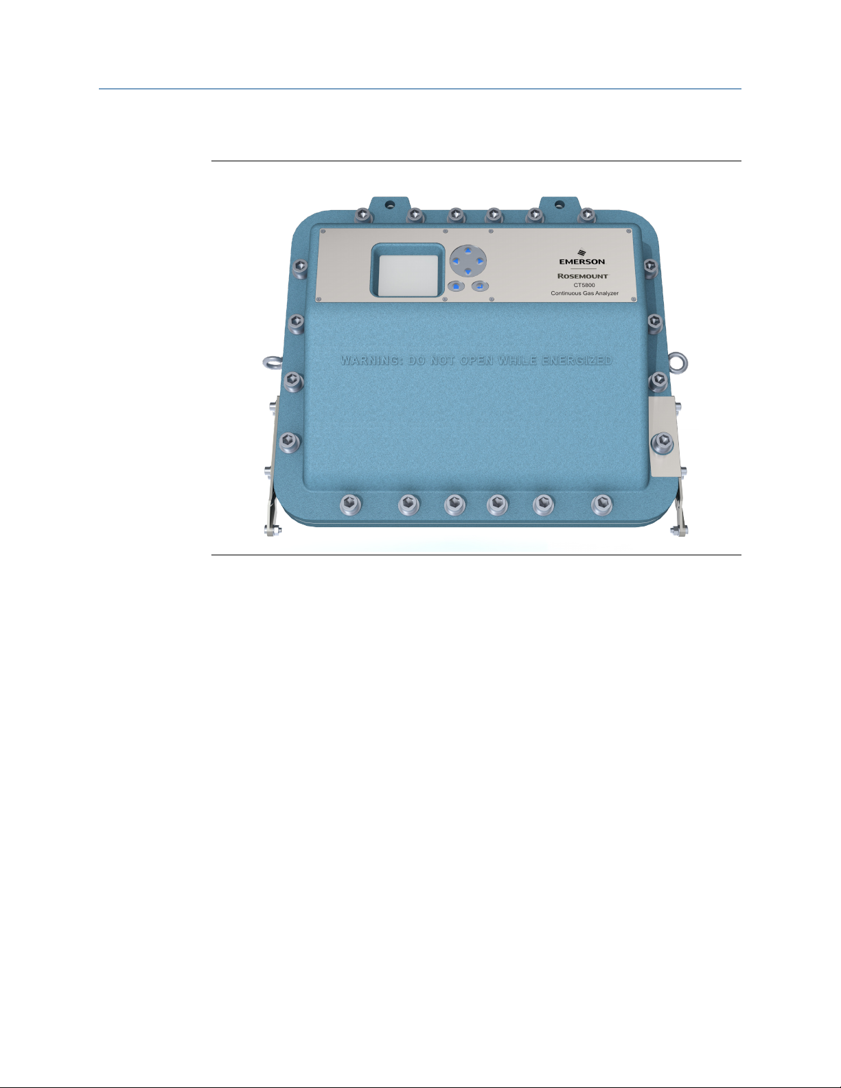
The types of molecules that are measured depend on the system configuration.
Figure 1-1: Rosemount CT5800
The analyzer can be configured to detect and measure up to twelve different gases,
depending on the combination of laser modules fitted.
1.3 System overview
A complete Rosemount™ CT5800 system consists of a gas handling system, the analyzer,
and the associated interconnecting wiring and gas piping.
Measurement data from the analyzer can be displayed in the process control center.
The Rosemount CT5800 is supplied by Emerson. The gas handling system may be
provided by either you or Emerson, depending upon the specific installation. The circuit
breakers used to control the application of electrical power to the analyzer, the
interconnecting wires, and gas piping are provided by you. In Figure 1-2, the items
supplied by Emerson are colored blue, customer-supplied items are colored purple, and
items that can be supplied by either Emerson or you are green. Table 1-1 lists the main
items of the system.
Rosemount CT5800 21
Plan Reference Manual
August 2020 00809-0100-5800
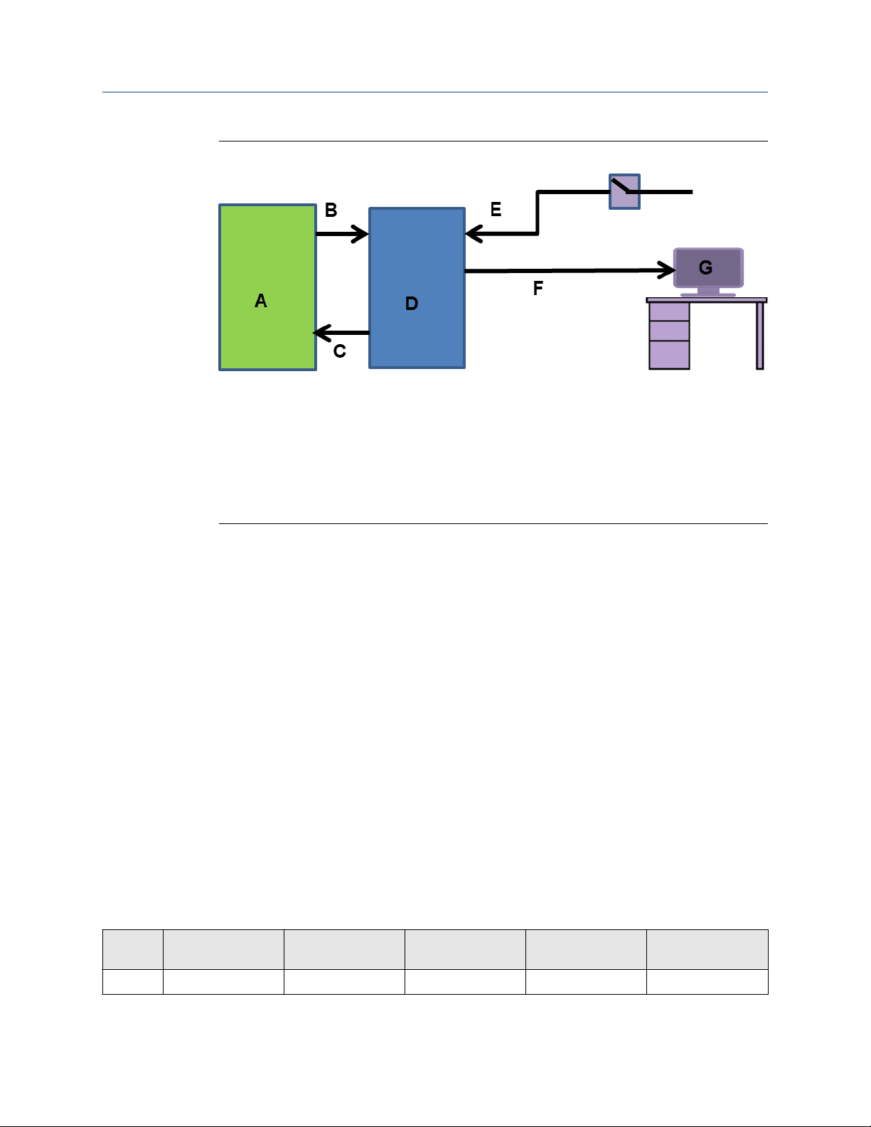
Figure 1-2: Complete Rosemount CT5800 Gas Analysis System
A. Gas handling system
B. Sample supply line
C. Sample ENTER (exhaust) line
D. Rosemount CT5800 gas analyzer
E. Electrical power
F. Measurement data
G. Control center
Emerson has designed the analyzer for industrial process applications requiring ATEX Zone
1 hazardous area certification; the analyzer has an Ex d flameproof enclosure. It contains
an optical system with multiple lasers and a series of optical components that provide an
optical path, a heated multi-pass analysis cell, and sample inlet and outlet ports that can
be connected to a gas handling system and control and analysis electronics. The number
of lasers installed depends upon customer requirements. The complete system operates
Vac from a 110/240 Vac 50/60 Hz supply.
The analyzer uses mid-infrared optical absorption spectroscopy to measure gas
concentrations. The light sources are lasers, which are operated to produce wavelength
sweeps that cover the absorption lines of the gases. The light from each laser is routed
through an optical path to the analysis cell, which provides measurement of low
concentrations of the subject gases. An external sample handling system conditions the
sample gas and draws it through the analysis cell. The light exits the multi-pass analysis
cell and is directed to a receiver in the analyzer. The variation in the intensity of light in the
vicinity of the absorption lines is measured, and the concentration is determined using a
comprehensive spectral fitting routine.
There is no sample conditioning provided within the analyzer; the sampled gas must be
brought within the parameters shown in Detailed system specifications before entering
the analyzer. Detailed characteristics of the analyzer are also given in Detailed system
specifications.
Table 1-1: Main Items of the Rosemount CT5800 System
Item Name or
description
Supplied by Part number Quantity Notes
1 Rosemount CT5800 Emerson 1 N/A
22 Emerson.com/Rosemount

Reference Manual
Plan
00809-0100-5800 August 2020
Table 1-1: Main Items of the Rosemount CT5800 System (continued)
Item Name or
description
2 Rosemount CT5800
software package,
version 5.x.x
3 Gas handling
system
4 Heated gas sample
line hose
5 Exhaust line hose
(for sample gas)
6 Reference gas
cylinders
(instrument gas) for
calibration purposes
7 Pressure regulator Customer Customer choice 1 per gas cylinder N/A
8 Pneumatic T-piece Customer Customer choice 1 N/A
9 Excess flow line Customer Customer choice 1 Required for
Supplied by Part number Quantity Notes
Emerson N/A 1 Software is
embedded in PC
board.
Version described in
manual
Customer
(optionally by
Emerson)
Customer/Emerson Customer choice 1 Optional supply by
Customer /Emerson Customer choice 1 Optional supply by
Customer Customer choice Dependent upon
Customer choice or
Emerson
1 Optional supply by
Emerson
Emerson
Emerson
N/A
number of gases
being measured
calibration
10 240 Vac power
cable
11 Cable from analyzer
to control center
12 Main circuit breaker Customer Customer choice 1 N/A
Customer Customer choice 1 Connect
Rosemount CT5800
to mains power
supply
Customer Customer choice 1 N/A
1.4 Customer information
This manual contains all the important information that must be followed to ensure the
correct operation and safety of personnel when operating the analyzer.
All personnel must read this manual carefully before commencing any work on the
analyzer.
For information regarding installation, consult Install and the Quick Start Guide.
Emerson is committed to continuously improving its products and documentation. Every
effort will be made to include in the documentation any modifications by the
manufacturer. However, this document reflects the supplied sensor at the revision date on
the front cover.
Should you require further information, or should particular problems arise that are not
covered in this manual, you can request additional help from Cascade Technical Support
Rosemount CT5800 23

Plan
August 2020 00809-0100-5800
(cascade.support@emerson.com) or Emerson distribution partners. Further contact
details for Emerson can be found on the back page of this manual.
Reference Manual
1.5 Safety precautions and conditions for safe use
WARNING
SAFE USE PRECAUTIONS
Before installing or performing any maintenance on the analyzer, read and understand the
safety information given in the preliminary information of this manual.
The analyzer described in this document has been quality control tested and left the
manufacturer in pristine condition. To achieve the correct and safe operation of this
product, it must be transported, installed, operated, and maintained as described by the
manufacturer.
All lasers used within the analyzer are Class 1. The emitted laser light is invisible (midinfrared) and the pulse duration so short that the unprotected eye will not be damaged.
The nature of the laser beam path and beam width further ensures that it should be
impossible to cause any eye damage. The analyzer has warning labels at appropriate
positions in accordance with USA 21 CFR 1040.10.
IECEx - Specific Condition of Use
• This equipment has flamepaths which differ from those in IEC 60079-1. Cascade
Technologies Ltd (cascade.support@emerson.com)shall be contacted for guidance
when maintaining the flamepaths.
• The fasteners which secure the cover are non-standard and shall therefore only be
replaced by fasteners supplied by the manufacturer for this purpose. The fasteners
must always be fitted with the washer supplied by the manufacturer.
• The equipment has non-conductive surfaces which are a potential electrostatic
charging hazard – see the instructions for guidance.
• The user shall ensure that the flow of process gas is limited to a maximum flow rate of 6
litres per minute.
• The equipment shallonly be used with process gases which are classified for equipment
group IIB + H2 and must not contain oxygen or any other oxidizer in concentrations
greater than that found in normal air.
CSA Certificate North American - Conditions of Acceptability
• The equipment has flameproof joints with dimensions which are other than those
specified in Table 2 of ANSI/UL 60079-1: 6th Edition and Table 3 of CSA C22.2
60079-1:16. These flameproof joints are not intended to be repaired but where
necessary the original manufacturer (cascade.support@emerson.com) shall be
contacted for guidance and information on the dimensions of the flameproof joints.
• The fasteners which secure the cover are non-standard and shall therefore only be
replaced by fasteners supplied by the manufacturer for this purpose. The fasteners
must always be fitted with the washer supplied by the manufacturer.
24 Emerson.com/Rosemount

Reference Manual Plan
00809-0100-5800 August 2020
• The equipment has non-conductive surfaces which are a potential electrostatic
charging hazard – see the instructions for guidance.
• The user shall ensure that the flow of process gas is limited to a maximum flow rate of 6
litres per minute.
• The equipment shall only be used with process gases which are in gas groups B, C or D
(Divisions) or IIB + H2 (Zones) and must not contain oxygen or any other oxidizer in
concentrations greater than that found in normal air.
• This assessment does not cover reliable function, performance, or other properties of
the equipment not related to safety.
• The equipment is to be installed using wire no larger than 1mm2 (18 AWG).
• The equipment is only to be installed by manufacturer trained personnel.
• If at any time there is a conflict between the system safety provisions and any relevant
local (national or regional) requirements, the local requirements always take
precedence.
• The equipment is not to be used with flammable liquids.
1.6 Qualified personnel
This manual provides installation, operation, and maintenance personnel with the level of
knowledge required to safely start, operate, and switch off the analyzer.
Only technically qualified personnel in the field of analysis and control who are familiar
with this manual and have been specially trained on the analyzer should install, operate,
switch off, and service the analyzer. Only qualified and trained persons have the required
specific knowledge to correctly interpret the general safety information, warnings, and
procedures given in this manual and apply them to this particular application. Emerson or
its distribution partners can provide this training on request.
Knowledge of the safety information within this manual and its technically correct
implementation are prerequisites for danger-free installation, operation, and maintenance
of the analyzer.
1.7 Software version
The analyzer includes software that is used to control the operation of the analyzer. This
document describes the software version as: 5.12.7 minimum.
1.8 Gas detection
The analyzer is highly configurable in the gases that can be detected and their range of
concentrations.
Rosemount CT5800 25

Plan Reference Manual
August 2020 00809-0100-5800
1.9 Detailed system specifications
Table 1-2 gives the physical characteristics of the analyzer. Figure 1-3 shows schematic
diagrams of the sensor and mounting points. Table 1-3 gives the general characteristics of
the analyzer.
Table 1-2: Physical Characteristics
Rosemount CT5800 Value Comment
External dimensions (closed) 694.5 x 292 x 515 mm
27.34 x 11.5 x 20.28 in.
External dimensions (open) 27.34 x 11.5 x 41.24 in.
694.5 x 292 x 1047.5 mm
Front panel swept radius 21.46 in.
545 mm
Weight 80 kg
176.37 lb.
Length x width x height
Nominal dimensions
Nominal dimensions, front panel at lowest point
To open the enclosure, the minimum height
required is 1030 mm (40.55 in.)
Allow sufficient space for the front panel to
swing through an arc of 180 ° (see Figure 1-5).
Approximate weight
The analyzer must be wall mounted. Do not
mount it on stud or partitioned walls.
Table 1-3: General Characteristics
Rosemount CT5800 Value Comment
Voltage 220/240 ± 10% Vac
110/120 ± 10% Vac
Peak power consumption 1100 W Max consumption per gas analyzer
Continuous steady-state power
consumption
Electrical compartment
enclosure
Optical compartment enclosure N/A Aluminum
800 W N/A
N/A Aluminum
50 Hz ± 5% (factory set)
60 Hz ± 5% (factory set)
Measurement technique N/A Mid IR absorption spectroscopy
Mid IR source N/A Quantum Cascade™ Laser
Near IR source N/A Interband Cascade Laser Tunable diode laser
Laser classification Class 1 BS EN 60825-1: 2007 safety of laser products. Equipment
classification and requirements (identical to IEC 60825-1
2007)
Inlet gas port connector ¼ in.
6 mm
Outlet (exhaust) gas port
connector
Measurement result signals 4 to 20 mA 4 or 8 channel outputs, specify on order
Warm-up time 90 minutes N/A
26 Emerson.com/Rosemount
¼ in.
6 mm
Swagelok® type, factory-configured, specify on order
Swagelok type, factory-configured, specify on order
Reference Manual Plan
00809-0100-5800 August 2020
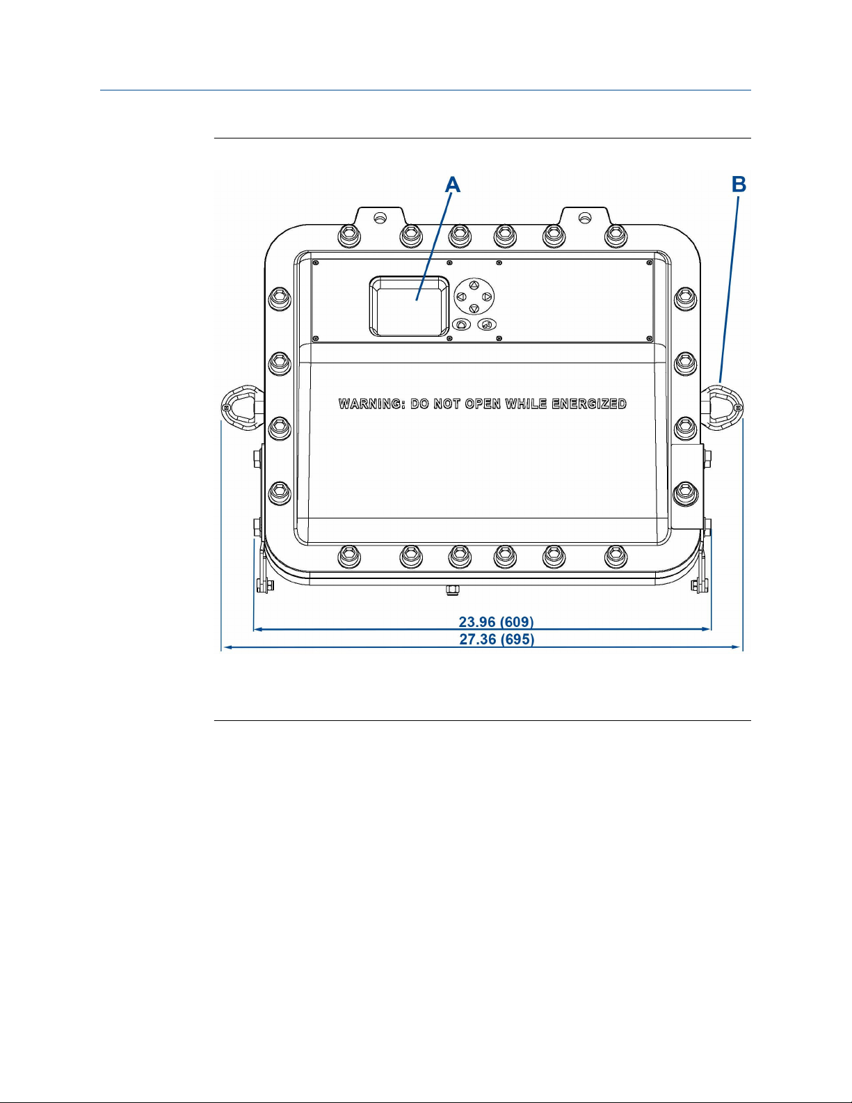
Figure 1-3: Rosemount CT5800 Dimensions: Front View
Dimensions are in inches (mm).
A. User interface
B. 2 off lifting eyelets
Rosemount CT5800 27

Plan Reference Manual
August 2020 00809-0100-5800
Figure 1-4: Rosemount CT5800 Dimensions: Side View
Dimensions are in inches (mm).
A. Rating plate
B. External earth point
28 Emerson.com/Rosemount

Reference Manual Plan
00809-0100-5800 August 2020
Figure 1-5: Rosemount CT5800 Radius for Opening
Dimensions are in inches (mm).
A. Opening arc
Table 1-4: Environmental Characteristics
Environmental characteristic Value Comment
Operating temperature range -4 to 131 °F (-20 to 55 °C) Ambient temperature
Sample gas temperature range 39 to 140 °F (4 to 60 °C)
Sample gas moisture content 8% Maximum (dependent on analyser
configuration)
Sample gas particulate density 5 mg/m
Sample gas particulate size 10 µm Maximum
IP code 66 IP to IEC 60529
Ambient humidity range 10 to 95% Relative humidity (non-condensing) at
3
Maximum
113 °F (45 °C)
Rosemount CT5800 29

Plan Reference Manual
August 2020 00809-0100-5800
1.9.1 Optical description
The laser modules are located in the core of the analyzer. Each laser module produces a
separate light beam, and these beams are combined linearly as the modules are aligned in
the system. The combined beams are closely coupled, parallel, and coaxial about a virtual
line. The laser light beams pass through an optical steering assembly, which directs the
laser beam through the sample cell.
The sample cell contains a set of mirrors to create a path through the sample gas that is
between 0.7 ft. (0.2 m) and 49.2 ft. (15 m) through multiple reflections along the length of
the cell. The laser beams exit the cell at the opposite end from where they entered and are
directed using a second optical block to a receiver.
By measuring and analyzing the light detected by the receiver unit, it is possible to
accurately determine the concentrations of the target molecules within the gas sample
cell.
1.10 Unpacking the analyzer
WARNING
HEAVY ITEM
In accordance with IEC 60079-0: 2011 Clause 30.
Failure to propery handle the analyzer may cause injury to personnel.
Make sure the wall the analyzer is mounted on is solid, stable, and of suitable material to
hold the weight of the analyzer.
Handle the analyzer with caution during unpacking, installing, maintaining, and
transporting to prevent crushing of hands, feet, or other body parts.
The analyzer weighs 176.4 lb. (80 kg).
Emerson recommends that a minimum of two people move and lift the analyzer.
Wear suitable protective gloves and protective footwear.
WARNING
TRANSPORTATION HAZARD
Failure to use proper lifting procedures may cause injury to personnel or damage the
analyzer.
Use safety-approved lifting equipment.
Follow safe lifting procedures for the weight and mass of the analyzer.
30 Emerson.com/Rosemount
 Loading...