

Installation, Operations, and Maintenance Manual
D-7010-0045, Rev C
January 2018
Rosemount™ CT5400 Continuous Gas Analyzer

Preface
Published by Emerson.
All possible care has been taken in the preparation of this publication, but Emerson and its agents and distributors accept no liability
for any inaccuracies that may be found. This manual reflects the state of the product at the issue date below, but further
enhancements while in service may mean that the manual does not reflect your particular system.
Emerson reserves the right to make changes without notice both to this publication and the products which it describes.
Document Number: D-7010-0045
Rev C, January 2018
©
Emerson 2017. All rights reserved.
No part of this publication may be reproduced, stored in a retrieval system, or transmitted in any form or by any means electronic,
mechanical, photocopying, recording, or otherwise without the express prior written permission of the copyright holder.
If you require additional technical assistance, request help from Cascade Technical Support (qcl.csc@emerson.com) or Emerson
distribution partners.
General inquiries about this or other Cascade Technologies products should be sent to qcl.csc@emerson.com.
All trademarks used within this document are the property of their respective owners.

Important information
NOTICE
This section is in accordance with IEC 60079-0: 2011 Clause 30. This section must not be changed, amended, or removed.
IMPORTANT: Users must read, understand and comply with the following information before proceeding.
All users, installers, operators, and maintainers must be familiar with operating the analyzer. To install, start up, operate, maintain
and service the analyzer in a safe manner, it is MANDATORY to read all additional instruction manuals shipped with the analyzer. The
following instruction manual(s) are available and / or referenced within this manual:
Rosemount CT5400 Quick Start Guide: D-7010-0061
All instructions must be saved for future use. Contact your local service center or sales office if you are missing documents.
User information
NOTICE
This section is in accordance with IEC 60079-0: 2011 Clause 30. This section must not be changed, amended, or removed.
Important
All users must read this page before proceeding!
Emerson (Rosemount) designs, manufactures, and tests its products to meet many national and international standards. The
Rosemount CT5400 is a sophisticated technical product, and to ensure it continues to operate as designed and within normal
specifications, it MUST be installed, used, and maintained correctly. The following instructions MUST be adhered to and integrated
into your safety program when installing, using, and maintaining Emerson (Rosemount) products.
• Failure to follow the proper instructions may cause:
- Loss of life
- Personal injury
- Damage to property
- Damage to this instrument
- Warranty invalidation
• Read all instructions prior to installing, operating, and servicing the product.
• If you do not understand any of the instructions, contact your Emerson (Rosemount) representative for clarification.
• Follow all warnings, cautions, and instructions marked on and supplied with the product.
• Inform and educate your personnel in the proper installation, operation, and maintenance of the product.
• Install your equipment as specified in the Installation Instructions of the appropriate manual and in accordance with
applicable local and national codes.
• Connect all products to the proper electrical and pressure sources.
• To ensure proper performance, use qualified personnel to install, operate, update, program, and maintain the product.
• When replacement parts are required, ensure that qualified people use replacement parts specified by Emerson
(Rosemount).
• Unauthorized parts and procedures can affect the product’s performance, place the safe operation of your process at risk,
and VOID YOUR WARRANTY. Look-alike substitutions may result in fire, electrical hazards, or improper operation.
• To prevent electrical shock and personal injury, all equipment doors must be closed and protective covers in place, except
when maintenance is being performed by qualified personnel.
• The information contained in this document is subject to change without notice.

General safety notice/residual risk
Installation, operation, and maintenance of the analyzer must be in accordance with these instructions.
When operated as intended and all applicable safety instructions are observed, an element of risk will remain, including, but not
limited to, the following:
• Explosion protection measures may become ineffective on the occurrence of one failure (for Category 3 instruments).
• The emission of gases hazardous to health may be possible when all gas connections have been correctly made.
To avoid exposure to the dangers of residual risks, take particular care when installing, operating, maintaining, and servicing the
analyzer.
Authorized personnel
NOTICE
This section is in accordance with IEC 60079-0: 2011 Clause 30. This section must not be changed, amended, or removed.
In-depth specialist knowledge is an absolute requirement for working with and on the analyzer. Personnel installing, operating,
servicing, and maintaining the analyzer must be instructed, trained, qualified, and authorized for hazardous areas with the
operating company and the manufacturer. It is the operating company's responsibility to:
• Train staff.
• Observe safety regulations.
• Follow the safety instructions and procedures in the product manual.
Operators must:
• Be trained.
• Read and understand all relevant sections of the product manual before commencing work.
• Know the safety mechanisms and regulations.
WARNING!
To avoid explosions, loss of life, personal injury, and damage to this equipment and on-site property, do not install, operate,
maintain, or service this instrument before reading and understanding this instruction manual and receiving appropriate training.

Regulations and standards
Regulations / Standards Description
2014/35/EU The Low Voltage Directive
2014/30/EU The Electromagnetic Compatibility Directive
2012/19/EU Waste Electrical and Electronic Equipment (WEEE) Directive
USA 21 CFR 1040.1 Laser products
NEC 505 National Electrical Code (issued by ANSI: American National Stand-
ards Institute and NFPA 70: National Fire Protection Association)
EN 6223: 2008 EMC Safety Standard
BS EN 60825-1:2007 Safety of laser products. Equipment classification and requirements
(identical to IEC 608250-1 2007).
BS EN 61010-1 2010 IEC 61010-1 2010 Safety requirements for electrical equipment for measurements,
control, and laboratory use. General requirements.
BS EN 61326-1: 2013 Electrical equipment for measurement, control, and laboratory use.
EMC requirements. General requirements.
Associated publications
Quick Start Guide: D-7010-0061
Compliance approvals
Waste disposal
Do not dispose of measuring tools into household waste.
Only for EC countries:
In accordance with European Directive 2012/19/EU for Waste Electrical and Electronic Equipment and its implementation into national right, measuring tools that are no longer usable must be collected separately and disposed of in
an environmentally correct manner.
This product complies with USA 21 CFR 1040.10. It is also designed and manufactured under an approved quality management system to ISO 9001:2008.
Emerson and the Rosemount CT5400 Gas Analyzer have satisfied the requirements for applying the CE marking to the Rosemount CT5400 Gas Analyzer.
This equipment meets all requirements of the EMC and Low Voltage directives.

Safety and information notices
DANGER!
WILL CAUSE DEATH
Failure to follow this warning will result in death or serious injury to personnel.
WARNING!
DANGER TO PERSONNEL
Failure to follow this warning may result in serious injury to personnel.
CAUTION!
MAY CAUSE DAMAGE TO EQUIPMENT
Failure to follow this warning may result in damage to the equipment.
NOTICE
Important or tip messages will appear in this format.

Safety Information
All authorized users, including installation, operation, and maintenance personnel, must observe the following safety precautions
and warnings.
DANGER!
ELECTRIC SHOCK
The analyzer operates using mains voltage that is dangerous to life. Make sure that the power ON/OFF switch at the rear of the panel
is set to OFF and tagged off before removing the top cover.
The analyzer must be earthed.
Death or personal injury may result if this is not observed.
DANGER!
FAILURE TO LOCK-OUT GAS HANDLING SYSTEM MAY CAUSE DEATH.
Always lock out the gas handling system when shutting down the analyzer. Unauthorized operation of the gas handling system
when maintenance is being performed on the analyzer or its associated pipes/hoses may result in highly flammable gas being
released, causing fire or explosion.
DANGER!
FAILURE TO VENT SAMPLE GAS MAY CAUSE DEATH.
The sample gas in the system must be vented to prevent fire or explosion during maintenance and to prevent damage to the
analyzer during startup.
The sample gas in the pipes leading to the analyzer must be purged to prevent hazards to personnel during maintenance. Purging
the sample gas must be done in accordance with the safe working procedures for the site.
Allow the analyzer and system for returning the sample gas to run for five minutes to allow any sample gas in the system to be
returned to the exhaust.
WARNING!
ELECTRICAL SHOCK HAZARD
Do not operate without covers secure.
Do not open while energized.
Installation requires access to live parts which can cause death or serious injury.
For safety and proper performance, this instrument must be connected to a properly grounded three-wire source of power.

WARNING!
LASER OPTICAL RADIATION EXPOSURE HAZARD
The analyzer contains lasers. Opening the analyzer and attempting to perform adjustments or procedures other than those specified
in this manual may result in hazardous optical radiation exposure.
All lasers used within the analyzer are Class 1. The emitted laser light is invisible (mid-infrared) and the combined laser powers are
sufficiently low at the first accessible aperture that the unprotected eye will not be damaged. This class is eye safe under all
operating conditions.
It is, however, possible to cause damage to the eye through not following correct procedures. Do not look at the laser with any kind
of magnifier or optical measuring device.
The use of control or adjustments or performance of procedures other than those specified herein may result in hazardous radiation
exposure.
WARNING!
HAZARDOUS SUBSTANCES
The analyzer may contain hazardous substances. Always handle the analyzer assemblies and components with extreme caution.
Gas handling components within the analyzer will contain particulate matter residue from the sample gases. Over the life of the
analyzer, the concentration of particulate matter will become enriched within the gas handling components. When performing
repairs and maintenance on the analyzer:
• Handle used gas handling components with extreme caution.
• Avoid direct skin contact with used gas handling components.
• Do not smoke, drink, or eat in the work area.
• Wear goggles or eye shields.
• Wear a suitable face mask to protect against inhalation of particulate matter.
• Do not wet fingers, eyes, or any exposed skin.
• Pack used gas handling components for disposal in sealed packaging and label them Contaminated.
Dispose of contaminated items as hazardous material according to the applicable local, national, or international health and safety
regulations and pollution regulations.
WARNING!
EXPLOSION HAZARD
Always lock-out tag-out the gas handling system when shutting down the analyzer. Unauthorized operation of the gas handling
system when maintenance is being performed on the analyzer or its associated pipes/hoses may result in highly flammable gas being
released, causing fire or explosion.
WARNING!
HEAVY ITEM
Handle the analyzer with caution during unpacking, installing, maintaining, and transporting to prevent crushing of hands, feet, or
other body parts.
The analyzer weighs 31 kg (68 lb). Always use suitable lifting/moving equipment when moving the analyzer. Wear suitable
protective gloves and protective footwear.
Failure to properly handle the analyzer may cause injury to personnel.
WARNING!
HAZARDOUS GAS
The product stream that the analyzer is examining may be hazardous even at low concentrations. Therefore, take special care to
ensure that the sample gas return port either returns the sample gas to the product stream or discharges the sample gas to a
location that will not cause a hazard.

WARNING!
HIGH PRESSURE GAS AND AIR
The calibration gas supply and compressed air supply operate at a pressure that can cause injury, e.g., damage to eyes and skin
punctures from debris blown by the high pressure gas or compressed air.
Always lock out or tag off the calibration gas supply and compressed air supply when shutting down the analyzer.
WARNING!
EXPLOSION HAZARD
The sample gas in the system must be vented to prevent fire or explosion during maintenance and to prevent damage to the
analyzer during startup.
The sample gas in the pipes leading to the analyzer must be purged to prevent hazards to personnel during maintenance. Purging
the sample gas must be done in accordance with the safe working procedures for the site.
Allow the analyzer and system for returning the sample gas to run for five minutes to allow any sample gas in the system to be
returned to the exhaust.
WARNING!
EXPLOSION
Danger of explosion if battery is incorrectly replaced. Replace only with the same or equivalent type.
CAUTION!
EQUIPMENT DAMAGE
Always follow the startup procedure. Damage to the analyzer may result from a failure to follow this procedure.
Failure to perform pre-system startup checks may cause damage to equipment.
CAUTION!
EQUIPMENT DAMAGE
Always follow the shutdown procedure. Damage to the analyzer may result from a failure to follow this procedure.
CAUTION!
UNSERVICEABLE EQUIPMENT
If the pressure and temperature measurements are out of tolerance, refer to Chapter 7 for guidance.
CAUTION!
EMC
This is a Class A product. In a domestic environment, this product may cause radio interference, in which case you may be required to
take adequate measures.
CAUTION!
EQUIPMENT DAMAGE
Ensure that the local power voltage where the unit is to be installed corresponds to the unit’s nominal voltage as given on the name
plate label.

CAUTION!
EQUIPMENT DAMAGE
Do not power up or try to operate the analyzer unless it is physically secure and all electrical and pneumatic connections to the
analyzer are in place.
Before commencing the start-up process, it is important to ensure that electrical power, sample gas handling facilities, and any
calibration gases that are required are available to the analyzer.

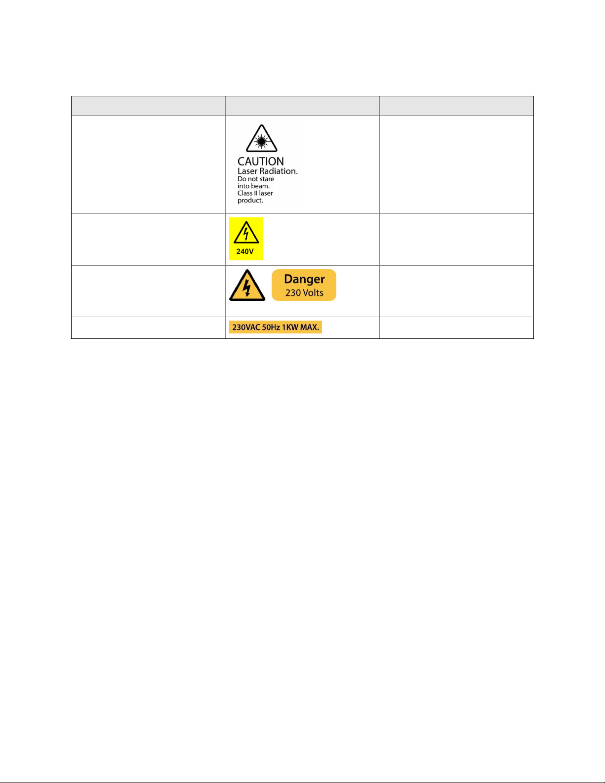
Safety and system labels and annotation
The labels and annotation applied to the analyzer are specified in the table below.
Label type Example Location
Identification label (including serial number, model number, and USA FDA compliance label
CAUTION - Hot label 1. Cell insulation
Laser radiation CAUTION label Baseplate
Made in the UK
Manufactured Sept. 2015
Rosemount CT5400 Continuous Gas
Analyzer
Serial number: CT5400-10008
Model number: CT5400
Glendevon House
Castle Business Park
Stirling, FK9 4TZ
United Kingdom
Tel. +44 (0)1786 447 721
Emerson.com/RosemountGasAnalysis
Rear panel
2. Both heated lines
3. Rack lid, near ventilation holes
Laser module identification label On each laser module housing
Earth identification label Back plate
WARNING statement Rear panel
Label type Example Location
CAUTION Laser Radiation safety statement Rear panel
AC power supply voltage label On analysis cell insulation
AC power supply Danger label 1. Rear panel, above mains power input
socket
2. On reverse of front panel, next to On/
Off switch
AC power supply label Rear panel, below power socket

Abbreviations
The following abbreviations are used in this manual.
Abbreviation Description
©
% Percent
< Less than
° Degree
AC Alternating current
Barg Pressure, in units of bars, above or below atmospheric pressure
BS British Standard
C Celsius
CE European Conformity
CFR Code of Federal Regulations
CH
4
CO Carbon monoxide
CO
2
DC Direct current
Deg Degree (temperature)
e.g. For example
EC European Community
EMC Electromagnetic compatibility
EU European Union
Hrs Hours
Hz Hertz
H2O Water
ICL Interband Cascade Laser
IEC International Electro-technical Commission
in. Inches
IP Ingress protection
IPxx Ingress protection (xx are numbers that define the protection level)
IS Intrinsically safe
ISO International Organization for Standardization
k Thousand
kg Kilogram
kHz Kilo hertz
L Liter
lb Pound
Copyright
Methane
Carbon dioxide

Abbreviation Description
LCD Liquid crystal display
LED Light emitting diode
L/min Liters per minute
m Meter
3
m
Cubic meter
mA Milliamp
Max Maximum
mBar milli-Bar
mbps Megabits per second
mg Milligram
3
mg/m
Microgram/cubic meter
Mid IR Mid Infrared
min Minute
mm Millimeter
N
2
Nitrogen
NEC National Electrical Code
NFPA National Fire Protection Association
nm Nanometer
NO Nitric oxide
NO
2
Nitrogen dioxide
N2O Nitrous oxide
NH
3
Ammonia
No. Number
O
2
Oxygen
PC Personal computer
PM Preventative maintenance
ppm Parts per million
psi Pounds per square inch
QCL Quantum Cascade Laser
TDL Tunable Diode Laser
Torr Unit of pressure defined as exactly 1/760 of a standard atmosphere
UKAS United Kingdom Accreditation Service
USA United States of America
USB Universal serial bus
V Volt
VA Volt-ampere
Vac Volt alternating current
Vdc Volt direct current
W Watt

Abbreviation Description
WEEE Waste electrical and electronic equipment
μm Micro-meter


Contents
Contents
Chapter 1 Plan ............................................................................................................................... 1
1.1 Description .................................................................................................................................. 1
1.2 Equipment purpose and role ........................................................................................................1
1.3 System overview ..........................................................................................................................2
1.4 Customer information ................................................................................................................. 4
1.5 Safety precautions and conditions for safe use .............................................................................5
1.6 Qualified personnel ......................................................................................................................6
1.7 Software version .......................................................................................................................... 6
1.8 Gas detection .............................................................................................................................. 6
1.9 Detailed system specifications .....................................................................................................6
1.9.1 Optical description ...................................................................................................... 10
1.10 Unpacking the analyzer ............................................................................................................. 10
Chapter 2 Install ...........................................................................................................................13
2.1 Site selection ............................................................................................................................. 13
2.2 Rack mounting the analyzer .......................................................................................................14
2.3 Gas inputs and outputs .............................................................................................................. 16
2.4 Connecting the electrical/electronic inputs and outputs ............................................................17
2.5 Commissioning the analyzer ......................................................................................................19
Chapter 3 Startup procedure ........................................................................................................21
3.1 Introduction .............................................................................................................................. 21
3.2 Preparation for use .................................................................................................................... 21
3.3 Startup procedure ..................................................................................................................... 22
Chapter 4 Operating the analyzer .................................................................................................25
4.1 Introduction .............................................................................................................................. 25
4.2 Normal operation ...................................................................................................................... 25
4.3 Front panel controls and indicators ............................................................................................26
4.4 Rear panel controls .................................................................................................................... 28
4.5 Display controller .......................................................................................................................28
4.6 Gas Sensor Main screen ............................................................................................................. 30
4.7 Pressure and Temperature screen ..............................................................................................31
4.8 Help system ...............................................................................................................................31
4.9 Main menu ................................................................................................................................ 32
4.10 BACK button .............................................................................................................................. 33
Chapter 5 Verifying Gas Concentrations ....................................................................................... 35
5.1 Verification ................................................................................................................................ 35
5.1.1 Zero verification .......................................................................................................... 35
5.1.2 Span verification ......................................................................................................... 39
Chapter 6 Gas Calibration Procedures ...........................................................................................45
6.1 Required tools ........................................................................................................................... 45
6.2 Main menu ................................................................................................................................ 45
6.3 Calibration .................................................................................................................................46
6.3.1 Zero calibration ........................................................................................................... 46
6.3.2 Span calibration .......................................................................................................... 51
6.4 Reference gas - suggested concentration ranges ....................................................................... 56
Installation, Operations, and Maintenance Manual i

Contents
Chapter 7 Troubleshooting and diagnostics ................................................................................. 57
7.1 Troubleshooting, repairs, and failure diagnostics .......................................................................57
7.2 Using the Built-in-Test (BIT) fault diagnostics .............................................................................59
7.3 Visual examination .................................................................................................................... 64
7.4 Failure diagnostics ..................................................................................................................... 65
7.5 Repairable items ........................................................................................................................68
7.6 Tools and test equipment required for troubleshooting .............................................................68
7.7 Removing the top cover .............................................................................................................69
7.8 Removing the bottom cover ...................................................................................................... 72
7.9 Replacing the LCD display ..........................................................................................................73
7.10 Replacing the USB circuit board ................................................................................................. 76
7.11 Replacing the power socket fuses .............................................................................................. 80
7.12 Replacing the internal fuses ....................................................................................................... 82
7.13 Replacing the fans ..................................................................................................................... 87
7.14 Replacing the terminal electric cooler (TEC) board .....................................................................89
7.15 Replacing the peripheral PCA board ...........................................................................................92
7.16 Replacing the motherboard ....................................................................................................... 95
7.17 Replacing the DIN Rail ................................................................................................................98
7.17.1 Replacing the analog input unit ...................................................................................98
7.17.2 Replacing the DC power supply .................................................................................101
7.17.3 Replacing the temperature controller ....................................................................... 102
7.17.4 Replacing the Ethernet switch ...................................................................................104
7.17.5 Replacing the laser modules ......................................................................................107
7.18 Replacing the gas temperature sensor ..................................................................................... 110
7.19 Replacing the pressure sensor ..................................................................................................112
7.20 Replacing the thermal cut-out ................................................................................................. 114
7.21 Replacing the gas input line ..................................................................................................... 117
7.22 Replacing the gas output line ...................................................................................................119
7.23 Replacing the analysis cell ........................................................................................................121
7.24 Cleaning the analysis cell mirrors ............................................................................................. 124
7.25 Installing the Top Cover ........................................................................................................... 127
7.26 Installing the bottom cover ......................................................................................................127
7.27 Downloading data for diagnostics and service ......................................................................... 128
7.27.1 Downloading data to a USB flash drive ...................................................................... 128
7.27.2 Downloading data using TFTP .................................................................................. 133
Chapter 8 Shutdown procedure ................................................................................................. 139
8.1 Shutdown procedure safety precautions .................................................................................139
8.2 Shutdown procedure ............................................................................................................... 140
Chapter 9 Preventative maintenance ......................................................................................... 145
9.1 Maintaining the analyzer ..........................................................................................................145
9.2 Scheduled maintenance .......................................................................................................... 145
Appendices and reference
Appendix A Theory of Operation ................................................................................................... 147
A.1 Overview ................................................................................................................................. 147
A.2 Quantum Cascade Laser measurement principle ..................................................................... 147
A.3 Process analyzer - gas concentration measurements ............................................................... 148
Appendix B Spare parts list ........................................................................................................... 149
ii Rosemount CT5400

Contents
Appendix C Engineering Drawings ................................................................................................151
C.1 Engineering drawings .............................................................................................................. 151
Installation, Operations, and Maintenance Manual iii

Contents
iv Rosemount CT5400

1 Plan
1.1 Description
The Rosemount™ CT5400 Continuous Gas Analyzer, hereafter referred to as the
Rosemount CT5400 or the analyzer, is an electronic sensor that uses laser spectroscopy to
perform analysis of process gas streams.
The function of the analyzer is to detect and measure up to twelve different types of gas at
concentrations ranging from parts per million (ppm) to percentage levels in the process
gas stream. The analyzer is designed to be mounted in a standard 482.6 mm (19 in.) rack.
WARNING!
HEAVY ITEM
Handle the analyzer with caution during unpacking, installing, maintaining, and transporting
to prevent crushing of hands, feet, or other body parts.
Plan
1.2
The analyzer weighs 31 kg (68 lb). Emerson™ recommends that the analyzer is only moved and
lifted by a minimum of two people. Wear suitable protective gloves and protective footwear.
Failure to properly handle the analyzer may cause injury to personnel.
This manual is intended for the personnel who install, operate, and maintain the
equipment.
Equipment purpose and role
The analyzer is a gas sensor system that can be configured to measure the concentrations
of multiple small molecules in a gas sample that is provided to the analyzer via a sample
line.
The types of molecules that are measured depend on the system configuration.
Installation, Operations, and Maintenance Manual 1
Plan
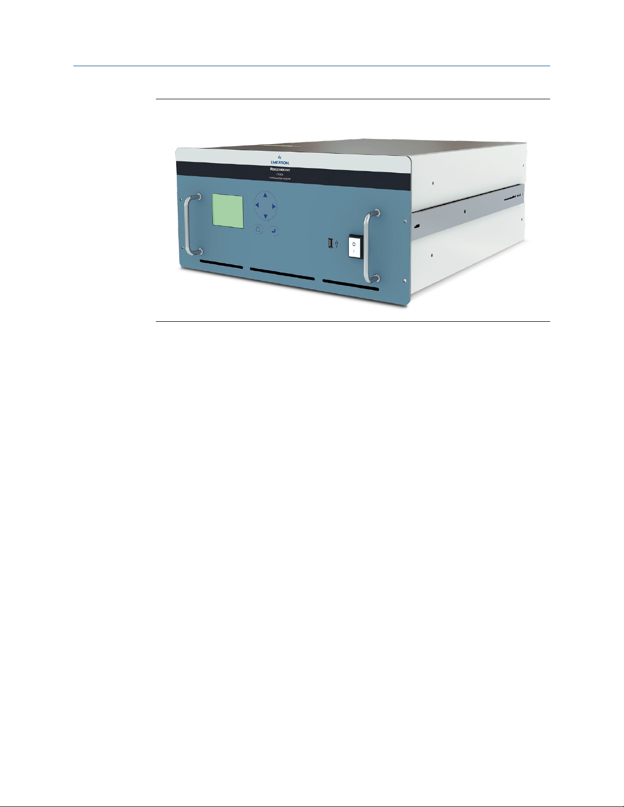
Rosemount CT5400Figure 1-1:
The analyzer can be configured to detect and measure up to twelve different gases,
depending on the combination of laser modules fitted.
1.3 System overview
A complete Rosemount CT5400 system consists of a gas handling system, the analyzer,
and the associated interconnecting wiring and gas piping.
Measurement data from the analyzer can be displayed in the process control center. You
must provide the gas handling system and interconnecting wiring and gas piping; Emerson
supplies the CT5400.
In Figure 1-2, the items supplied by Emerson are colored orange; the items supplied by you
are colored blue. Table 1-1 lists the main items of the system.
2 Rosemount CT5400

Plan
Complete Rosemount CT5400 Gas Analysis SystemFigure 1-2:
A. Gas handling system
B. Sample supply line
C. Sample return (exhaust) line
D. Rosemount CT5400 Gas Analyzer
E. Electrical power
F. Measurement data
G. Control center
The analyzer contains an optical system with multiple lasers and a series of optical
components that provide an optical path, a heated multi-pass analysis cell, and sample
and outlet ports that can be connected to a gas handling system, and control and analysis
electronics. The number of lasers installed depends upon customer requirements. The
complete system operates from a 240 Vac 50 Hz supply.
Gas concentrations are measured using mid-infrared optical absorption spectroscopy. The
light sources are quantum cascade lasers (QCLs), which are operated to produce
wavelength sweeps that cover the absorption lines of the gases. The light from each laser
is routed through an optical path to the analysis cell, which provides measurement of low
concentrations of the subject gases. An external sample handling system conditions the
sample gas and draws it through the analysis cell. The light exits the multi-pass analysis cell
and is directed to a receiver in the analyzer. The variation in the intensity of light in the
vicinity of the absorption lines is measured, and the concentration is determined using a
comprehensive spectral fitting routine.
There is no sample conditioning provided within the analyzer; the sampled gas must be
brought within the parameters shown in Section 1.9 before entering the analyzer. Detailed
characteristics of the analyzer are also given in Section 1.9.
Main Items of the Rosemount CT5400 SystemTable 1-1:
Item Name or description Supplied by Part number Quantity Notes
1 Rosemount CT5400 Emerson CT5400 1
2 Rosemount CT5400 software
package, version 5.x.x
3 Gas handling system Customer Customer choice 1
Emerson N/A 1 Software is
embedded in
PC board.
Version described in
manual
Installation, Operations, and Maintenance Manual 3

Plan
Main Items of the Rosemount CT5400 System (continued)Table 1-1:
Item Name or description Supplied by Part number Quantity Notes
4 Heated gas sample line hose Customer Customer choice 1
5 Exhaust line hose (for sample
gas)
6 Reference gas cylinders (in-
strument gas) for calibration
purposes
7 Pressure regulator Customer Customer choice 1 per gas cylin-
8 Pneumatic T-piece Customer Customer choice 2 Required for
9 Excess flow line Customer Customer choice 1 Required for
10 240 Vac power cable Customer Customer 1
11 Cable from analyzer to con-
trol center
12 482.6 mm (19 in.) rack sys-
tem
Customer Customer choice 1
Customer Customer choice Dependent
upon number of
gases being
measured
Required for
der
Customer Customer choice 1 1
Customer Customer choice 1 Holds the
calibration
calibration
calibration
CT5400
1.4 Customer information
This manual contains all the important information that must be followed to ensure the
correct operation and safety of personnel when operating the analyzer.
All personnel must read this manual carefully before commencing any work on the
analyzer.
For information regarding installation, consult Chapter 2 and the Quick Start Guide
(D-7010-0052).
Emerson is committed to continuously improving its products and documentation. Every
effort will be made to include in the documentation any modifications by the
manufacturer. However, it should be noted that this document reflects the supplied
sensor at the revision date on the front cover.
Should you require further information, or should particular problems arise that are not
covered in this manual, you can request additional help from Cascade Technical Support
(qcl.csc@emerson.com) or Emerson distribution partners. Further contact details for
Emerson can be found on the back page of this manual.
4 Rosemount CT5400

1.5 Safety precautions and conditions for safe use
WARNING!
Before installing or performing any maintenance on the analyzer, read and understand the
safety information given in the preliminary information of this manual.
The analyzer described in this manual has been quality control tested and left the
manufacturer in pristine condition. To achieve the correct and safe operation of this
product, it must be transported, installed, operated, and maintained as described by the
manufacturer.
All lasers used within the instrument are Class 1. The emitted laser light is invisible (midinfrared) and the pulse duration so short that the unprotected eye will not be damaged.
The nature of the laser beam path and beam width further ensures that it should be
impossible to cause any eye damage. The instrument has warning labels at appropriate
positions in accordance with USA 21 CFR 1040.10.
Conditions for safe use
• This equipment has flamepaths which differ from those in IEC60079-1/EN 60079-1.
Cascade Technologies, Ltd (qcl.csc@emerson.com) must be contacted for guidance
when maintaining the flamepaths.
• The fasteners which secure the cover are non-standard and shall therefore only be
replaced by fasteners supplied by the manufacturer for this purpose. The fasteners
must always be fitted with the washer supplied by the manufacturer.
• The equipment has non-conductive surfaces which are a potential electrostatic
charging hazard - see instructions for guidance.
• The process gas flow rate is limited to a maximum of 6 liters per minute.
• The equipment shall only be used with process gases which are in gas groups B, C or
D (Divisions) or IIB + H 2 (Zones) and must not contain oxygen or any other oxidizer
in concentrations greater than that found in normal air.
Plan
CSA Certificate North American conditions
• The equipment has flameproof joints with dimensions which are other than those
specified in Table 2 of ANSI/UL 60079-1: 6th edition and Table 3 of CSA C22.2
60079-1:16. These flameproof joints are not intended to be repaired, but where
necessary the original manufacturer shall be contacted for guidance and
information on the dimensions of the flameproof joints.
• The fasteners which secure the cover are non-standard and shall therefore only be
replaced by fasteners supplied by the manufacturer for this purpose. The fasteners
must always be fitted with the washer supplied by the manufacturer.
• The equipment has non-conductive surfaces which are a potential electrostatic
charging hazard – see the instructions for guidance.
• The user shall ensure that the flow of process gas is limited to a mazimum flow rate
of 6 liters per minute.
Installation, Operations, and Maintenance Manual 5

Plan
• The equipment shall only be used with process gases which are in gas groups B, C or
D (Divisions) or IIB + H2 (Zones) and must not contain oxygen or any other oxidizer in
concentrations greater than that found in normal air.
• This assessment does not cover reliable function, performance, or other properties
of the equipment not related to safety.
• The equipment is to be installed using wire no larger than 1mm2 (18 AWG).
• The equipment is only to be installed by manufacturer trained personnel.
• If at any time there is a conflict between the system safety provisions and any
relevant local (national or regional) requirements, local requirements always take
precedence.
• The equipment is not to be used with flammable liquids.
1.6 Qualified personnel
This manual provides installation, operation, and maintenance personnel with the level of
knowledge required to safely start, operate, and switch off the analyzer.
1.7
1.8
Only technically qualified personnel in the field of instrumentation and control who are
familiar with this manual and have been specially trained on the analyzer should install,
operate, switch off, and service the analyzer. Only qualified and trained persons have the
required specific knowledge to correctly interpret the general safety information,
warnings, and procedures given in this manual and apply them to this particular
application. Emerson or its distribution partners can provide this training on request.
Knowledge of the safety information within this manual and its technically correct
implementation are prerequisites for danger-free installation, operation, and maintenance
of the analyzer.
Software version
The analyzer includes software that is used to control the operation of the instrument. This
manual describes software version 5.x.x.
Gas detection
The analyzer is highly configurable in the gases that can be detected and their range of
concentrations.
1.9
6 Rosemount CT5400
Detailed system specifications
Table 1-2 gives the physical characteristics of the analyzer. Schematic diagrams of the
sensor and mounting points are shown in Figure 1-3, Figure 1-4, and Figure 1-5. Table 1-3
gives the general characteristics of the instrument.

Physical CharacteristicsTable 1-2:
Rosemount CT5400 Value Units Comment
External dimensions 482.6 x 673 x 221.5
19 x 26.5 x 8.7
Weight 31
68.34
mm
in.
kg
lb
Length x Width x Height
Nominal dimensions
Approximate weight
General CharacteristicsTable 1-3:
Rosemount CT5400 Value Units Comment
Supply voltage 240 Vac 50 Hz
Peak power consumption
Continuous steadystate power consumption
Frame and structure
material
Housing material - - Powder coated steel
Wetted materials PFA coated aluminum, 315 stainless steel,
Measurement technique
Mid IR source - - Quantum Cascade Laser
Laser classification Class 1 BS EN 60825-1: 2007 safety of laser products.
Inlet gas port connector
Outlet (exhaust) gas
port connector
Measurement result
signals
Warm-up time 90 minutes
600 W Max consumption
300 W Once the gas analyzer has stabilized and the
analysis cell has reached the temperature set
point
- -
- - Mid IR absorption spectroscopy
6
1/4
6
1/4
4 to 20 mA 4 or 8 channel outputs, specify on order
mm
in.
mm
in.
Anodized and powder coated aluminum
FKM and FFKM seals, CaF2 and BaF2 windows,
protected gold coated aluminum mirrors
Equipment classification and requirements
(identical to IEC 60825-1 2007)
Swagelok type, factory-configured, specify on
order
Swagelok type, factory-configured, specify on
order
Plan
Installation, Operations, and Maintenance Manual 7
Plan
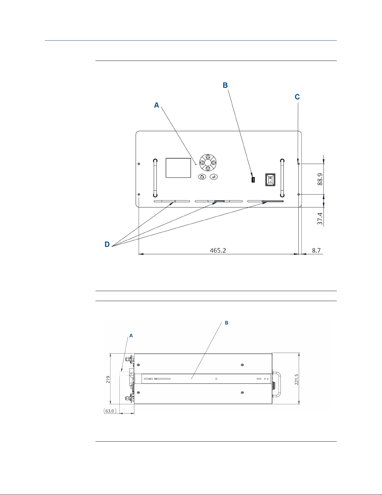
Dimensions - Front ViewFigure 1-3:
A. User interface
B. Data extraction port
C. 4 off Ø system locking holes
D. Ventilation. Do not obstruct.
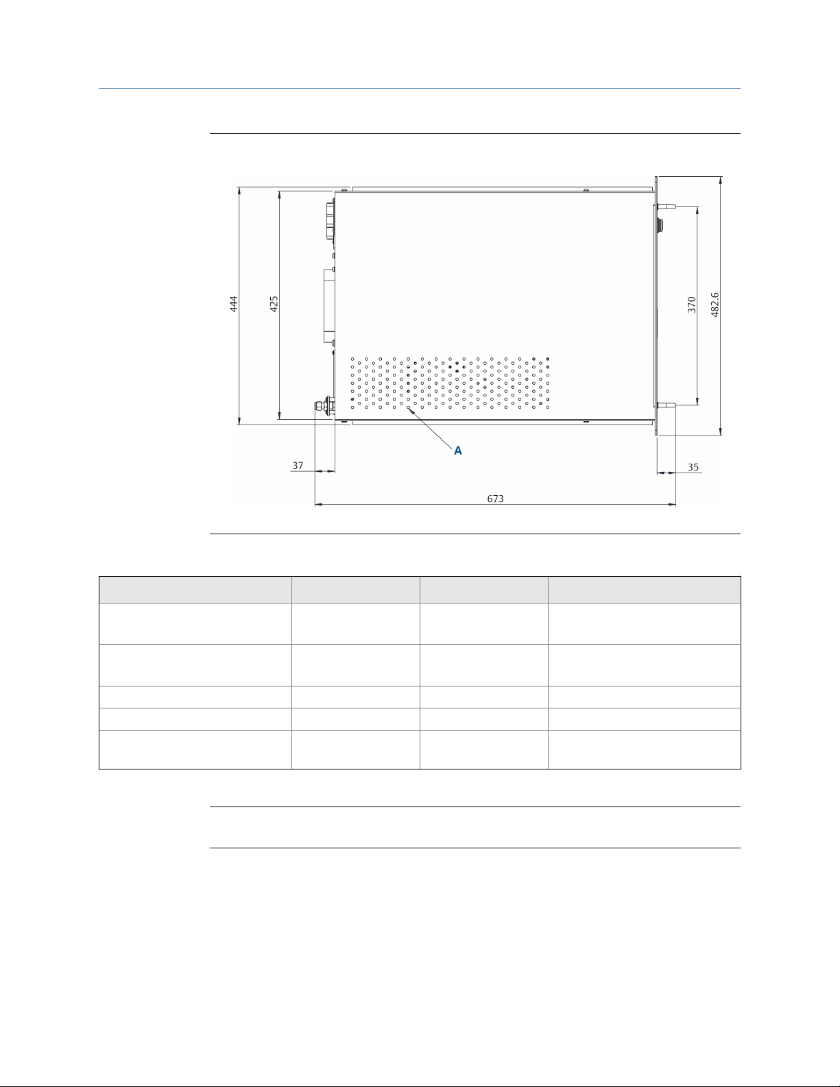
Dimensions - Side ViewFigure 1-4:
A. Handle swings out 63 mm (2.5 in.)
B. 2 off telescopic slide, 610 mm (24 in.) long, 55 kg (121.3 lb.) max load. 50.8 mm (2 in.) over travel.
9.6 mm (.4 in.) slide thickness. Lock-out. Front disconnect.
8 Rosemount CT5400
Plan
Dimensions - Top ViewFigure 1-5:
A. Ventilation. Do not obstruct.
Environmental CharacteristicsTable 1-4:
Environmental characteristic Value Units Comment
Operating temperature range 0 to 45
32 to 113
Sample gas temperature range 50 to 195
122 to 383
Sample gas particulate density 5 mg/m
Sample gas particulate size 10 μm Maximum
Sensor humidity range 10 to 95 % Relative humidity (non-condens-
Note
The CT5400 Continuous Gas Analyzer is suitable for indoor use only
°C
°F
°C
°F
Ambient temperature
Factory set, specify on order
3
Maximum
ing) at 45 °C (113 °F)
Installation, Operations, and Maintenance Manual 9

Plan
1.9.1 Optical description
The laser modules are located in the core of the analyzer. Each laser module produces a
separate light beam, and these beams are combined linearly as the modules are aligned in
the system. The combined beams are closely coupled, parallel, and coaxial about a virtual
line. The laser light beams pass through a baseplate onto an optical steering assembly,
which directs the laser beam through the sample cell.
The sample cell contains a set of mirrors to create a path through the sample gas that is
between 2 m and 5 m through multiple reflections along the length of the cell. The laser
beams exit the cell at the opposite end from where they entered and are directed using a
second optical block to a receiver.
By measuring and analyzing the light detected by the receiver unit, it is possible to
accurately determine the concentrations of the target molecules within the gas sample
cell.
1.10 Unpacking the analyzer
This procedure may require a minimum of two people to safely remove the equipment
from the shipping container.
WARNING!
HEAVY ITEM
Handle the analyzer with caution during unpacking, installing, maintaining, and transporting
to prevent crushing of hands, feet, or other body parts.
The analyzer weighs 31 kg (68 lb). Emerson™ recommends that the analyzer is only moved and
lifted by a minimum of two people. Wear suitable protective gloves and protective footwear.
Failure to properly handle the analyzer may cause injury to personnel.
WARNING!
TRANSPORTATION HAZARD
Use safety-approved lifting equipment. You must ensure safe lifting procedures for the weight
and mass of the equipment are followed.
Failure to use proper lifting procedures may cause injury to personnel or damage the analyzer.
Procedure
1. Visually inspect the exterior of the analyzer for signs of damage, corrosion, gas
leaks, or signs of previously overheating.
2. Report anything found to the maintenance organization.
3. One person carefully guides and assists the other person lifting the equipment from
the container.
4. If necessary, use safety approved and tested lifting equipment to remove the
analyzer from the shipping container.
10 Rosemount CT5400
 Loading...