

Reference Manual
00809-0100-4731, Rev FA
April 2003
TM
and Radar Gauges
www.rosemount.com

Reference Manual
00809-0100-4731, Rev FA
April 2003
APEX™ and APEX Sentry™ Radar Gauge
APEX™ and APEX Sentry™
Radar Gauge
NOTICE
Read this manual before working with the product. For personal and system safety, and for
optimum product performance, make sure you thoroughly understand the contents before
installing, using, or maintaining this product.
Within the United States, Rosemount Inc. has two toll-free assistance numbers.
Customer Central: 1-800-999-9307(7:00 a.m. to 7:00 p.m. CST)
Technical support, quoting, and order-related questions.
North American1-800-654-7768 (24 hours a day – Includes Canada)
Response Center: Equipment service needs.
For equipment service or support needs outside the United States, contact your local
Rosemount representative.
The products described in this document are NOT designed for nuclear-qualified
applications.
Using non-nuclear qualified products in applications that require nuclear-qualified hardware
or products may cause inaccurate readings.
For information on Rosemount nuclear-qualified products, contact your local Rosemount
Sales Representative.
Rosemount APEX Radar Gauge may be protected by U.S. Patent Nos. 4,945,360 and 5,546,088 and
other U.S. and foreign patents and patents pending.
Rosemount and the Rosemount logotype are registered trademarks of Rosemount Inc.
PlantWeb is a trademark of the Fisher-Rosemount group of companies.
APEX, APEX Sentry, and the APEX logotypes are trademarks of Rosemount Inc.
HART is a registered trademark of the HART Communication Foundation.
Teflon, VITON, and Kalrez are registered trademarks of E.I. du Pont de Nemours & Co.
Cover Photo: APEX002C
www.rosemount.com


Reference Manual
00809-0100-4731, Rev FA
April 2003
APEX™ and APEX Sentry™ Radar Gauge
Table of Contents
SECTION 1
Introduction
SECTION 2
Installation
Using This Manual . . . . . . . . . . . . . . . . . . . . . . . . . . . . . . . . . . . . . . . . 1-1
Safety Messages . . . . . . . . . . . . . . . . . . . . . . . . . . . . . . . . . . . . . . . . . 1-2
Overview . . . . . . . . . . . . . . . . . . . . . . . . . . . . . . . . . . . . . . . . . . . . . . . 1-3
Components of the APEX and
APEX Sentry Radar Gauges . . . . . . . . . . . . . . . . . . . . . . . . . . . . . 1-5
System Architecture. . . . . . . . . . . . . . . . . . . . . . . . . . . . . . . . . . . . . . . 1-6
APEX /Hybrid System Overview
(APEX Radar Gauge Only). . . . . . . . . . . . . . . . . . . . . . . . . . . . . . . 1-7
Addressing Concerns about Exposure to
The APEX and APEX Sentry Radar Gauges . . . . . . . . . . . . . . . . . 1-7
Service Support . . . . . . . . . . . . . . . . . . . . . . . . . . . . . . . . . . . . . . . . . . 1-8
Safety Messages . . . . . . . . . . . . . . . . . . . . . . . . . . . . . . . . . . . . . . . . . 2-2
Before You Install . . . . . . . . . . . . . . . . . . . . . . . . . . . . . . . . . . . . . . . . 2-3
Considerations. . . . . . . . . . . . . . . . . . . . . . . . . . . . . . . . . . . . . . . . . . . 2-4
Telecommunications Agency Requirements . . . . . . . . . . . . . . . . . 2-4
Operation Requirements . . . . . . . . . . . . . . . . . . . . . . . . . . . . . . 2-4
Tank Requirements . . . . . . . . . . . . . . . . . . . . . . . . . . . . . . . . . . 2-4
Unpacking the APEX and APEX Sentry Radar Gauges. . . . . . . . . 2-5
Installation Considerations . . . . . . . . . . . . . . . . . . . . . . . . . . . . . . . 2-5
Process Characteristics . . . . . . . . . . . . . . . . . . . . . . . . . . . . . . . . . 2-5
Dielectric Constant . . . . . . . . . . . . . . . . . . . . . . . . . . . . . . . . . . 2-5
Foam and Vapors . . . . . . . . . . . . . . . . . . . . . . . . . . . . . . . . . . . 2-6
Changing Density, Temperature, or Pressure. . . . . . . . . . . . . . 2-6
Turbulence or Vortices . . . . . . . . . . . . . . . . . . . . . . . . . . . . . . . 2-6
Coating, Condensate, or Corrosion. . . . . . . . . . . . . . . . . . . . . . 2-7
Vessel Characteristics . . . . . . . . . . . . . . . . . . . . . . . . . . . . . . . . . . . . . 2-7
General Vessel Considerations . . . . . . . . . . . . . . . . . . . . . . . . . . . 2-9
Heating Coils and Agitators. . . . . . . . . . . . . . . . . . . . . . . . . . . . 2-9
Cables, Floats, Baffles, or Trays . . . . . . . . . . . . . . . . . . . . . . . . 2-9
Inlet Pipes or Flows . . . . . . . . . . . . . . . . . . . . . . . . . . . . . . . . . 2-10
Specific Tank Shapes. . . . . . . . . . . . . . . . . . . . . . . . . . . . . . . . . . 2-10
Spherical Vessel Considerations. . . . . . . . . . . . . . . . . . . . . . . 2-10
Horizontal Vessel Mounting Surface . . . . . . . . . . . . . . . . . . . . 2-11
Stilling Well, Bypass Cage, and
Bridle Connection Considerations . . . . . . . . . . . . . . . . . . . . . . 2-12
Nozzle Considerations . . . . . . . . . . . . . . . . . . . . . . . . . . . . . . . . . 2-13
Non-horizontal Mounting Surface . . . . . . . . . . . . . . . . . . . . . . 2-13
Tank Nozzle Considerations . . . . . . . . . . . . . . . . . . . . . . . . . . 2-14
Process Windows . . . . . . . . . . . . . . . . . . . . . . . . . . . . . . . . . . . . . . . 2-16
Mechanical Installation . . . . . . . . . . . . . . . . . . . . . . . . . . . . . . . . . . . 2-20
www.rosemount.com

APEX™ and APEX Sentry™ Radar Gauge
Mounting Considerations . . . . . . . . . . . . . . . . . . . . . . . . . . . . . . . 2-20
Flange Sizes . . . . . . . . . . . . . . . . . . . . . . . . . . . . . . . . . . . . . . 2-20
Access Clearances . . . . . . . . . . . . . . . . . . . . . . . . . . . . . . . . . 2-20
Wall, Nozzle, or Standoff Clearance . . . . . . . . . . . . . . . . . . . . 2-20
Mounting the Gauge . . . . . . . . . . . . . . . . . . . . . . . . . . . . . . . . . . . . . 2-21
Electrical Installations . . . . . . . . . . . . . . . . . . . . . . . . . . . . . . . . . . . . 2-22
Check Processor Switches. . . . . . . . . . . . . . . . . . . . . . . . . . . . . . 2-22
Electrical Considerations . . . . . . . . . . . . . . . . . . . . . . . . . . . . . . . 2-23
Conduit Connections . . . . . . . . . . . . . . . . . . . . . . . . . . . . . . . . 2-23
Grounding the Gauge Housing . . . . . . . . . . . . . . . . . . . . . . . . 2-23
Transient Protection . . . . . . . . . . . . . . . . . . . . . . . . . . . . . . . . 2-24
External Power Shut-off Switch. . . . . . . . . . . . . . . . . . . . . . . . 2-24
Electrical Considerations . . . . . . . . . . . . . . . . . . . . . . . . . . . . . . . . . . 2-24
Cable Selection . . . . . . . . . . . . . . . . . . . . . . . . . . . . . . . . . . . . . . 2-24
Power Requirements . . . . . . . . . . . . . . . . . . . . . . . . . . . . . . . . . . 2-24
Power vs. Distance Requirements . . . . . . . . . . . . . . . . . . . . . . . . 2-25
Hazardous Locations . . . . . . . . . . . . . . . . . . . . . . . . . . . . . . . . . . 2-25
DC Main Power Supply with 4–20 mA Loop
Power Supply . . . . . . . . . . . . . . . . . . . . . . . . . . . . . . . . . . . . . . . . 2-25
DC Main Power Supply Fuse Size and Type . . . . . . . . . . . . . 2-26
DC Main Power Supply with No Loop Power Supply . . . . . . . . . . 2-27
AC Main Power Supply with 4–20 mA Loop
Power Supply . . . . . . . . . . . . . . . . . . . . . . . . . . . . . . . . . . . . . . . . 2-28
AC Main Power Supply Fuse Size and Type . . . . . . . . . . . . . 2-29
Wiring Optional Gauge Devices. . . . . . . . . . . . . . . . . . . . . . . . . . . . . 2-29
Model 751 Field Signal Indicator . . . . . . . . . . . . . . . . . . . . . . . . . 2-29
(APEX Radar Gauge and APEX Sentry Radar Gauge) . . . . . 2-29
APEX/Hybrid System Installation (APEX Radar Gauge Only) . . . 2-31
3- or 4-Wire RTD (APEX Radar Gauge Only) . . . . . . . . . . . . . . . 2-32
Powering Up . . . . . . . . . . . . . . . . . . . . . . . . . . . . . . . . . . . . . . . . . . . 2-33
Reference Manual
00809-0100-4731, Rev FA
April 2003
SECTION 3
Configuration
TOC-2
Safety Messages . . . . . . . . . . . . . . . . . . . . . . . . . . . . . . . . . . . . . . . . . 3-1
Basic Configuration Parameters . . . . . . . . . . . . . . . . . . . . . . . . . . . . . 3-2
Key Measurement Values . . . . . . . . . . . . . . . . . . . . . . . . . . . . . . . 3-2
Reference Gauge Height. . . . . . . . . . . . . . . . . . . . . . . . . . . . . . 3-2
Minimum Clearance to Product Level . . . . . . . . . . . . . . . . . . . . 3-3
Maximum Range . . . . . . . . . . . . . . . . . . . . . . . . . . . . . . . . . . . . 3-3
Upper Range Value (20 mA Point) . . . . . . . . . . . . . . . . . . . . . . 3-3
Lower Range Value (4 mA Point) . . . . . . . . . . . . . . . . . . . . . . . 3-3
Volume Parameters. . . . . . . . . . . . . . . . . . . . . . . . . . . . . . . . . . 3-4
Special Cases. . . . . . . . . . . . . . . . . . . . . . . . . . . . . . . . . . . . . . . . . 3-4
Dish-bottom Tanks, Empty Tank Detection . . . . . . . . . . . . . . . . 3-4
Null Zones . . . . . . . . . . . . . . . . . . . . . . . . . . . . . . . . . . . . . . . . . 3-6
Field Configuration Using the Integral
Display Option . . . . . . . . . . . . . . . . . . . . . . . . . . . . . . . . . . . . . . . . . . . 3-6
(APEX Radar Gauge Only). . . . . . . . . . . . . . . . . . . . . . . . . . . . . . . 3-6
Starting the Main Menu . . . . . . . . . . . . . . . . . . . . . . . . . . . . . . . . . 3-7
Setting Configuration Options. . . . . . . . . . . . . . . . . . . . . . . . . . . . . 3-8

Reference Manual
00809-0100-4731, Rev FA
April 2003
APEX™ and APEX Sentry™ Radar Gauge
Configuration Options Form . . . . . . . . . . . . . . . . . . . . . . . . . . . . . . 3-9
Setting the Language . . . . . . . . . . . . . . . . . . . . . . . . . . . . . . . 3-11
Setting the Output Units . . . . . . . . . . . . . . . . . . . . . . . . . . . . . 3-11
Setting the Display Units . . . . . . . . . . . . . . . . . . . . . . . . . . . . . 3-11
Setting the Reference Gauge Height . . . . . . . . . . . . . . . . . . . 3-12
Setting the 4 mA Calibration . . . . . . . . . . . . . . . . . . . . . . . . . . 3-13
Setting the 20 mA Calibration . . . . . . . . . . . . . . . . . . . . . . . . . 3-14
Exiting the Main Menu . . . . . . . . . . . . . . . . . . . . . . . . . . . . . . . . . 3-15
Model 275 HART Communication Option . . . . . . . . . . . . . . . . . . . . . 3-15
Commissioning on the Bench With HART . . . . . . . . . . . . . . . . . . 3-15
Setting the Loop to Manual. . . . . . . . . . . . . . . . . . . . . . . . . . . . . . 3-17
Wiring Diagrams . . . . . . . . . . . . . . . . . . . . . . . . . . . . . . . . . . . . . . 3-17
Bench Hook-up . . . . . . . . . . . . . . . . . . . . . . . . . . . . . . . . . . . . 3-17
Field Hook-up . . . . . . . . . . . . . . . . . . . . . . . . . . . . . . . . . . . . . 3-17
Connections and Hardware . . . . . . . . . . . . . . . . . . . . . . . . . . . . . 3-18
Using a Model 275 HART Communicator . . . . . . . . . . . . . . . . 3-18
Set Transmitter Units . . . . . . . . . . . . . . . . . . . . . . . . . . . . . . . . . . 3-18
Set Reference Gauge Height . . . . . . . . . . . . . . . . . . . . . . . . . . . . 3-18
Set 4 and 20 mA Points . . . . . . . . . . . . . . . . . . . . . . . . . . . . . . . . 3-18
Volume Configuration (APEX Radar Gauge Only) . . . . . . . . . . . . 3-18
Set Volume Units . . . . . . . . . . . . . . . . . . . . . . . . . . . . . . . . . . . . . 3-19
Set Primary Variable. . . . . . . . . . . . . . . . . . . . . . . . . . . . . . . . . . . 3-19
Set Range Values
(4 and 20 mA points) . . . . . . . . . . . . . . . . . . . . . . . . . . . . . . . . . . 3-19
Choose Tank Type . . . . . . . . . . . . . . . . . . . . . . . . . . . . . . . . . . . . 3-19
Enter Tank Dimensions . . . . . . . . . . . . . . . . . . . . . . . . . . . . . . . . 3-19
Enter Strapping Table Information . . . . . . . . . . . . . . . . . . . . . . . . 3-19
Standard Volume (Apex Radar Gauge Only) . . . . . . . . . . . . . . . . 3-20
Enable RTD Input . . . . . . . . . . . . . . . . . . . . . . . . . . . . . . . . . . . . . 3-20
Enter Volume Coefficients . . . . . . . . . . . . . . . . . . . . . . . . . . . . . . 3-20
AMS Configuration Tool Option . . . . . . . . . . . . . . . . . . . . . . . . . . . . . 3-21
Basic Setup . . . . . . . . . . . . . . . . . . . . . . . . . . . . . . . . . . . . . . . . . 3-21
Strapping Table . . . . . . . . . . . . . . . . . . . . . . . . . . . . . . . . . . . . . . 3-22
Transmitter Variables . . . . . . . . . . . . . . . . . . . . . . . . . . . . . . . . . . 3-23
Rerange . . . . . . . . . . . . . . . . . . . . . . . . . . . . . . . . . . . . . . . . . . . . 3-24
Radar Configuration Tool (RCT) Option . . . . . . . . . . . . . . . . . . . . . . 3-25
Installing the RCT Software . . . . . . . . . . . . . . . . . . . . . . . . . . . . . 3-25
Specifying the COM Port . . . . . . . . . . . . . . . . . . . . . . . . . . . . . . . 3-26
Using the Setup Wizard . . . . . . . . . . . . . . . . . . . . . . . . . . . . . . . . 3-27
Using the Setup Function . . . . . . . . . . . . . . . . . . . . . . . . . . . . . . . 3-28
Setup - Info . . . . . . . . . . . . . . . . . . . . . . . . . . . . . . . . . . . . . . . 3-29
Setup - Basics . . . . . . . . . . . . . . . . . . . . . . . . . . . . . . . . . . . . . 3-29
Setup- Output . . . . . . . . . . . . . . . . . . . . . . . . . . . . . . . . . . . . . 3-30
Setup - Tank Config . . . . . . . . . . . . . . . . . . . . . . . . . . . . . . . . 3-31
Setup - Volume . . . . . . . . . . . . . . . . . . . . . . . . . . . . . . . . . . . . 3-32
Setup - LCD. . . . . . . . . . . . . . . . . . . . . . . . . . . . . . . . . . . . . . . 3-33
Setup - Advanced . . . . . . . . . . . . . . . . . . . . . . . . . . . . . . . . . . 3-34
Logging Measurement Data . . . . . . . . . . . . . . . . . . . . . . . . . . 3-36
Saving the log to a disk . . . . . . . . . . . . . . . . . . . . . . . . . . . . . . 3-37
Using the Advanced Tab . . . . . . . . . . . . . . . . . . . . . . . . . . . . . . . 3-38
Tank Plotting . . . . . . . . . . . . . . . . . . . . . . . . . . . . . . . . . . . . . . 3-38
Memory Map . . . . . . . . . . . . . . . . . . . . . . . . . . . . . . . . . . . . . . 3-38
TOC-3

APEX™ and APEX Sentry™ Radar Gauge
Reference Manual
00809-0100-4731, Rev FA
April 2003
SECTION 4
Hardware and Software
Maintenance and
Troubleshooting
APPENDIX A
Reference Data
Safety Messages . . . . . . . . . . . . . . . . . . . . . . . . . . . . . . . . . . . . . . . . . 4-1
Preventive Maintenance . . . . . . . . . . . . . . . . . . . . . . . . . . . . . . . . . . . 4-2
Product Buildup . . . . . . . . . . . . . . . . . . . . . . . . . . . . . . . . . . . . . . . 4-2
Splashing and Coating . . . . . . . . . . . . . . . . . . . . . . . . . . . . . . . 4-2
Performance . . . . . . . . . . . . . . . . . . . . . . . . . . . . . . . . . . . . . . . . . . 4-3
Alarm and Diagnostic Messages . . . . . . . . . . . . . . . . . . . . . . . . . . . . . 4-3
Local Operator Interface Display . . . . . . . . . . . . . . . . . . . . . . . . . . . . . 4-7
HART Communicator Software Diagnostics . . . . . . . . . . . . . . . . . . . . 4-7
AMS Configuration Software Diagnostics . . . . . . . . . . . . . . . . . . . . . . 4-8
Removing the Gauge Housing From the Flange . . . . . . . . . . . . . . . . 4-10
Antenna Selection Guidelines . . . . . . . . . . . . . . . . . . . . . . . . . . . . . . . A-1
Telecom Restrictions . . . . . . . . . . . . . . . . . . . . . . . . . . . . . . . . . . . . . .A-2
Equipment Description. . . . . . . . . . . . . . . . . . . . . . . . . . . . . . . . . . . . . A-4
Performance Specifications . . . . . . . . . . . . . . . . . . . . . . . . . . . . . . . . . A-4
Environmental Conditions . . . . . . . . . . . . . . . . . . . . . . . . . . . . . . . . . .A-5
Process Conditions. . . . . . . . . . . . . . . . . . . . . . . . . . . . . . . . . . . . . A-5
Electrical Specifications . . . . . . . . . . . . . . . . . . . . . . . . . . . . . . . . . . . . A-5
Power Supply . . . . . . . . . . . . . . . . . . . . . . . . . . . . . . . . . . . . . . . . .A-7
Input . . . . . . . . . . . . . . . . . . . . . . . . . . . . . . . . . . . . . . . . . . . . . . . . A-7
Output. . . . . . . . . . . . . . . . . . . . . . . . . . . . . . . . . . . . . . . . . . . . . . .A-7
Calibration . . . . . . . . . . . . . . . . . . . . . . . . . . . . . . . . . . . . . . . . . . . . . . A-7
Software Functionality . . . . . . . . . . . . . . . . . . . . . . . . . . . . . . . . . . . . .A-7
Weight . . . . . . . . . . . . . . . . . . . . . . . . . . . . . . . . . . . . . . . . . . . . . . . . . A-7
Materials of Construction . . . . . . . . . . . . . . . . . . . . . . . . . . . . . . . . . . . A-8
Mounting. . . . . . . . . . . . . . . . . . . . . . . . . . . . . . . . . . . . . . . . . . . . .A-8
Size. . . . . . . . . . . . . . . . . . . . . . . . . . . . . . . . . . . . . . . . . . . . . . . . . A-8
Options . . . . . . . . . . . . . . . . . . . . . . . . . . . . . . . . . . . . . . . . . . . . . .A-8
Dimensional Drawings . . . . . . . . . . . . . . . . . . . . . . . . . . . . . . . . . . . . . A-9
Ordering Information . . . . . . . . . . . . . . . . . . . . . . . . . . . . . . . . . . . A-12
Configuration Data Sheet . . . . . . . . . . . . . . . . . . . . . . . . . . . . A-16
Tagging . . . . . . . . . . . . . . . . . . . . . . . . . . . . . . . . . . . . . . . . . .A-16
APPENDIX B
Product Certificates
TOC-4
Approved Manufacturing Locations . . . . . . . . . . . . . . . . . . . . . . . . B-1
European Directive Information . . . . . . . . . . . . . . . . . . . . . . . . . . . . . . B-1
ATEX Directive . . . . . . . . . . . . . . . . . . . . . . . . . . . . . . . . . . . . . . . .B-1
Flame-Proof enclosure Ex d protection type in
accordance with EN50 018 . . . . . . . . . . . . . . . . . . . . . . . . . . . .B-1
European Pressure Equipment Directive (PED) (97/23/EC) . . . . . B-1
Electro Magnetic Compatibility (EMC) (89/336/EEC) . . . . . . . . . . . B-2
Low Voltage Directive (93/68/EEC) . . . . . . . . . . . . . . . . . . . . . . . . B-2
Other important guidelines . . . . . . . . . . . . . . . . . . . . . . . . . . . . . . .B-2
Hazardous Locations Certifications . . . . . . . . . . . . . . . . . . . . . . . . . . . B-2
North American Certifications . . . . . . . . . . . . . . . . . . . . . . . . . . B-2
Approval Drawings. . . . . . . . . . . . . . . . . . . . . . . . . . . . . . . . . . . . . . . . B-3

Reference Manual
00809-0100-4731, Rev FA
April 2003
APEX™ and APEX Sentry™ Radar Gauge
Section 1 Introduction
Using This Manual . . . . . . . . . . . . . . . . . . . . . . . . . . . . . . . page 1-1
Safety Messages . . . . . . . . . . . . . . . . . . . . . . . . . . . . . . . . . page 1-2
Overview . . . . . . . . . . . . . . . . . . . . . . . . . . . . . . . . . . . . . . . page 1-3
System Architecture . . . . . . . . . . . . . . . . . . . . . . . . . . . . . . page 1-6
Service Support . . . . . . . . . . . . . . . . . . . . . . . . . . . . . . . . .page 1-8
USING THIS MANUAL NOTE
All information included refers to both the APEX Radar Gauge
and the APEX Sentry Radar Gauge unless otherwise stated.
Section 2: Installation
• Mechanical considerations
• Electrical considerations
• Mounting, wiring, and field configuration instructions
Section 3: Configuration
• Field Configuration Using the Integral Display
• Level Configuration
• Volume Configuration
Section 4: Hardware and Software Maintenance and Troubleshooting
• Preventive maintenance
• Hardware and software diagnostic messages
Appendix A: Reference Data
• Specifications
• Dimensional Drawings
• Ordering Information
Appendix B: Product Certificates
• European ATEX Directive information
• Examples of intrinsic safety labels
• Approval drawings for installation
www.rosemount.com

Reference Manual
00809-0100-4731, Rev FA
APEX™ and APEX Sentry™ Radar Gauge
April 2003
SAFETY MESSAGES Procedures and instructions in this manual may require special precautions to
ensure the safety of the personnel performing the operations. Information that
raises potential safety issues is indicated by a warning symbol ( ). Refer to
the safety messages listed at the beginning of each section before performing
an operation preceded by this symbol.
Explosions could result in death or serious injury:
Verify that the operating environment of the gauge is consistent with the appropriate
hazardous locations certifications.
Before connecting a HART-based communicator in an explosive atmosphere, make sure
the instruments in the loop are installed in accordance with intrinsically safe or
non-incendive field wiring practices.
Failure to follow safe installation and servicing guidelines could result in death or
serious injury:
Make sure only qualified personnel perform these procedures.
Use the equipment only as specified in this manual. Failure to do so may impair the
protection provided by the equipment.
Do not perform any service other than those contained in this manual unless you are
qualified.
As a matter of routine, shut off the APEX Radar Gauge and all other equipment in the tank
before you enter the tank.
1-2

Reference Manual
00809-0100-4731, Rev FA
April 2003
APEX™ and APEX Sentry™ Radar Gauge
OVERVIEW The APEX and APEX Sentry Radar Gauges use a radar signal to measure
the level of liquid in a vessel. Because the radar gauge is mounted on top of a
vessel and its components do not contact the product, it is a dependable
alternative to a standard insertion device that can become broken or corroded
when inserted into the process. The APEX Radar Gauge also works well in
turbulent, aerated, solids-laden, viscous, or corrosive liquids, and thick pastes
or slurries.
The advanced 24 GHz frequency technology in the gauges significantly
increases the reliability of your level measurement for a wide range of tank
level applications. The gauges use radar technology based on frequency
modulated continuous wave (FMCW) transmission of microwaves. Radar
(microwave) signals are sent from the gauge to the surface of the material
and reflected back to the gauge receiver. The receiver evaluates the
frequency difference between the transmitted and returned signals. The
gauge analyzes the signals to determine the distance to the product surface.
The 24 GHz frequency and advanced electronics allow the radar gauges to
use a small antenna and maintain a narrow beamwidth. The small, lightweight
antenna simplifies installation while the narrow beamwidth allows unwanted
echoes from vessel obstructions such as agitators, heat exchangers, filling
pipes, baffles, thermowells, and intermittent filling streams to be avoided. The
narrow beam also increases mounting flexibility because the gauge can be
mounted on existing flanges located close to tank walls.
1-3
Reference Manual
00809-0100-4731, Rev FA
April 2003
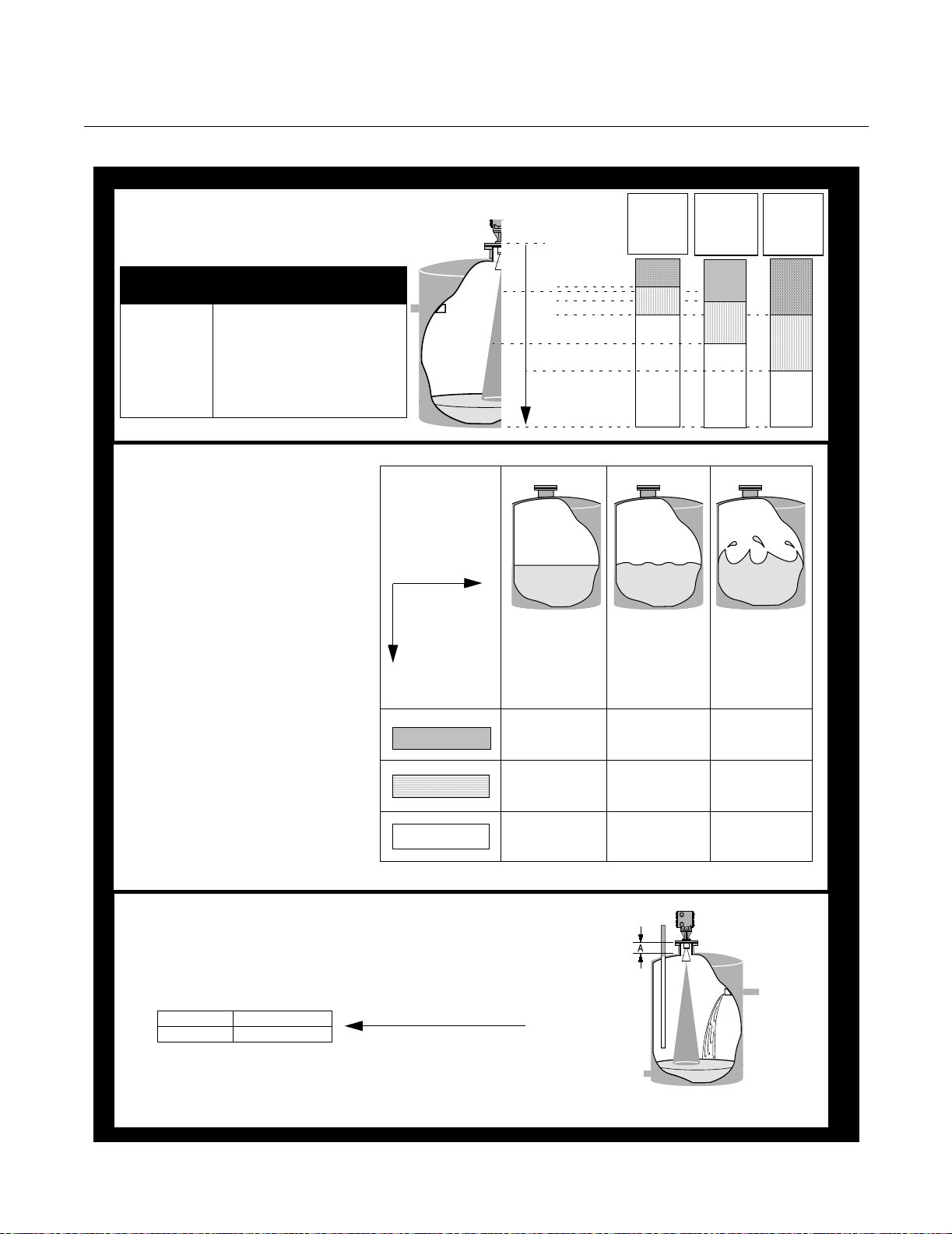
Which Radar Gauge is Best for Your Level Measurement Application?
APEX™ and APEX Sentry™ Radar Gauge
Step 1. Dielectric vs. Distance
Choose the appropriate
shaded region for the application.
Dielectric
Constant, ε
(1)
1.5 - 4.0
4.0 - 10.0 Organic or concentrated acids,
> 10.0 Water-based fluids, alcohols,
(1) Consult Factory when dielectric less than 4
Liquid Examples
r
Hydrocarbons, petrochemicals,
freons, vegetable oils, toluene,
...
organic solvents, ...
dilute acids, acetone, glycols, ...
Step 2. Liquid Surface Quality
Dielectric vs.
(from Step 1.)
Distance Region
Match surface
quality with
shaded region
from Step 1.
Region A
Region B
Region C
Dielectric
Constant
0 m
5 m (16.4 ft)
7,5 m (24.6 ft)
10 m (32.8 ft)
15 m (49.2 ft)
20 m (65.6 ft)
Maximum Distance
30 m (98.4 ft)
CALM
No waves,
storage
Possible
SENTRY-
go to Step 3.
Possible
SENTRY-
go to step 3.
APEX APEX APEX
1.5 to 4.0
Region
Region
Region
Surface Quality
MOVING
Mild rolling,
no splashing,
surface
unbroken
Possible
SENTRY-
go to step 3.
APEX APEX
A
B
C
Dielectric
Constant
4.0 to 10.0
Region
Region
Region
Dielectric
Constant
> 10.0
APEX
Region
Region
Region
(1)
A
B
C
TURBULENT
Heavy
agitation,
vapors, filling,
splashing, or
reactions
A
B
C
Step 3. Tank Geometry
YES APEX Sentry
NO APEX only
NOTE: To meet most telecommunications requirements, the APEX and APEX
Sentry Radar Gauges must be installed on enclosed or vented metal tanks.
However, other tank types may be approved in country of final destination. Refer to
product manual (document number 00809-0100-4731) for detailed information.
Is flange height
(A) 0,5 m (19.6 in)?
— AND —
Is the radar beam free
of any obstructions, such as fill
tubes, baffles, or
exposed agitators?
*
* See “Antenna Selection
Guidelines” on page A-1
LEVEL-APEX_07A, APEX_08A, APEX_011A
1-4
Reference Manual
00809-0100-4731, Rev FA
April 2003
APEX™ and APEX Sentry™ Radar Gauge
Components of the
APEX and
APEX Sentry Radar
Gauges
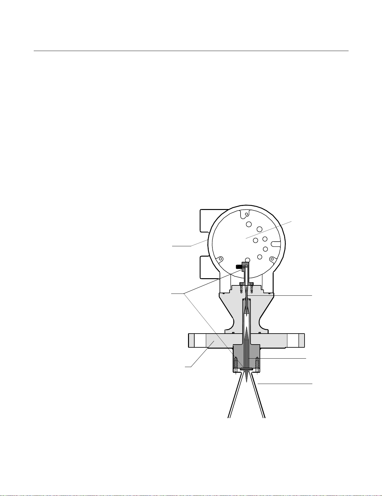
Figure 1-1. Cross-sectional View
of the APEX Radar Gauge
The top of the APEX and APEX Sentry Radar Gauges is an aluminum gauge
housing (see Figure 1-1). The gauge housing includes advanced radar
electronics for signal processing.
The radar electronics is the heart of the gauge. It produces an
electromagnetic wave by using an oscillator that converts direct current (dc)
power into a radar signal. It also receives the return signal.
The radar signal passes from the electronics through a waveguide containing
an alumina ceramic process barrier. The waveguide is the entire path from
the electronics to the antenna.
The antenna is a cone-shaped device made of stainless steel. The antenna
controls the signal beamwidth by helping to keep the radar signal focused on
its target (the product in the tank) so it does not spread out over the entire
vessel and give false echoes. A larger antenna provides a more focused,
narrow beam. (Refer to Appendix A: Reference Data for further information
regarding beamwidth.)
Radar
Electronics
Aluminum
Gauge
Housing
Waveguide
Flange
Alumina
Ceramic
Tef lon
Vapor Seal
Antenna
1-5
Reference Manual
00809-0100-4731, Rev FA
April 2003
APEX™ and APEX Sentry™ Radar Gauge
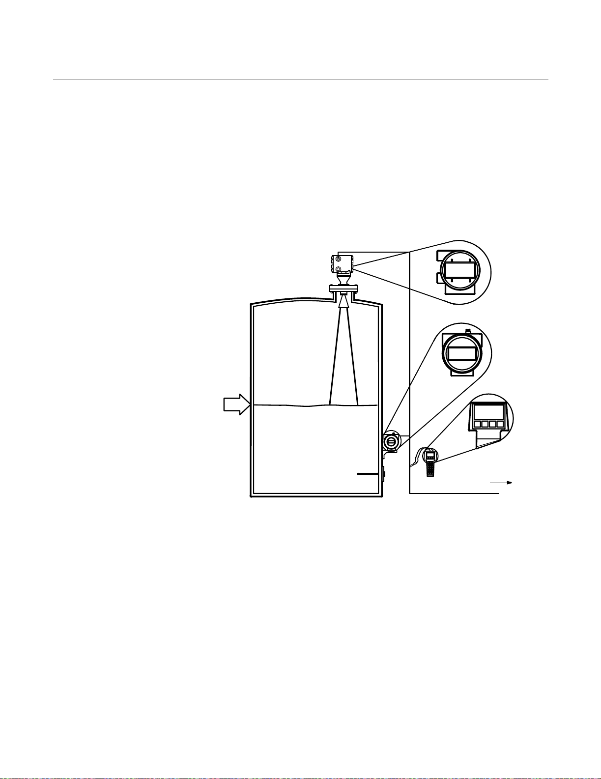
SYSTEM ARCHITECTURE
Figure 1-2. APEX System
Architecture and Display
Options
The output of the APEX and APEX Sentry Radar Gauges is a 4–20 mA
analog signal superimposed with a digital HART signal. As a result, the
primary variable (4–20 mA output) can be configured to represent either level
(APEX and APEX Sentry Radar Gauges) or calculated volume (APEX Radar
Gauge only), with up to three additional variables available through the HART
signal.
In addition to using the HART Communicator, you can view level and volume
variables using an optional Integral Display on the gauge or a Model 751 Field
Signal Indicator as a remote display (see Figure 1-2).
Optional
Integral Display
Level: 5.10 m
4
–
2
0
Level=
5.10 m
m
A
/
H
A
R
T
S
i
g
n
a
l
Level: 5.10 m
Model 751 Field
Signal Indicator
HART
Communicator
Control System
Level: 5.10 m
LEVEL-0006B
1-6

Reference Manual
00809-0100-4731, Rev FA
April 2003
APEX™ and APEX Sentry™ Radar Gauge
APEX /Hybrid
System Overview
(APEX Radar
Gauge Only)
Figure 1-3. Hybrid System
Option
To maximize the number of available on-line inventory measurements, you
can install and combine an APEX Radar Gauge with a Rosemount
industry-leading pressure transmitter to create a hybrid system (see Figure
1-3). A hybrid system offers the best advantages from both level-based and
pressure-based tank gauging systems:
• Offers all the advantages of the APEX and HTG technologies
• Provides level, volume, mass, and true average
density measurements
• Enhances plant safety since no manual operations are necessary
• Handles traditional problems such as density stratification
For further installation details, please see page 2-1, and refer to the certified
wiring diagrams provided.
APEX
Radar Gauge
Model 3201
HIU
MCAP
Output
HART
Communicator
Addressing Concerns
about Exposure to
The APEX and APEX
Sentry Radar Gauges
Optional
RTD
Optional Pressure Transmitter
RS 485
RS 232
Output
Model 3402 AIM
The Federal Communications Commission has issued a bulletin called
Questions and Answers About Biological Effects and Potential Hazards of
Radio frequency Radiation (OET Bulletin No. 56, Third Edition, January
1989). This document states a recommended power density limit of 5
mW/cm
2
in the frequency range of 1.5–100 GHz. This limit is based on a 1982
ANSI guideline for a time-averaged exposure for humans.
The maximum power density emitted from APEX and APEX Sentry Radar
Gauges is approximately 1.1 mW/cm
When the gauge is mounted in a metal vessel, the emissions external to the
vessel are much lower than the 1.1 mW/cm
2
, which is below the ANSI guideline.
2
measured at the antenna.
For additional information about the safety of radar signals, see Appendix A:
Reference Data.
LEVEL- 2510_04A
1-7

Reference Manual
00809-0100-4731, Rev FA
April 2003
APEX™ and APEX Sentry™ Radar Gauge
SERVICE SUPPORT If you have reason to believe that your APEX or APEX Sentry Radar Gauge
may need to be returned for service, please contact a Level Applications
Support Specialist at Rosemount Customer Central (1-800-999-9307). They
will help you determine the best course of action, and may transfer you to
either an Order Administrator or to the Rosemount North American Response
Center (NARC) to arrange the return of your gauge for service or repair.
NOTE
Most radar problems encountered in the field are applications-related, and
can best be dealt with while the gauge is installed.
The representative arranging the return will ask for product model and serial
numbers, and will provide a Return Material Authorization (RMA) number.
The center will also ask for the name of the process material to which the
product was last exposed. If the material to which the product was last
exposed is a hazardous substance as defined by OSHA, a copy of the
required Material Safety Data Sheet (MSDS) for each hazardous substance
identified must be included with the returned products.
The representative arranging your return will detail the additional information
and procedures necessary to return products exposed to hazardous
substances.
1-8

Reference Manual
00809-0100-4731, Rev FA
April 2003
APEX™and APEX Sentry™ Radar Gauge
Section 2 Installation
Safety Messages . . . . . . . . . . . . . . . . . . . . . . . . . . . . . . . . . page 2-2
Before You Install . . . . . . . . . . . . . . . . . . . . . . . . . . . . . . . . page 2-3
Considerations . . . . . . . . . . . . . . . . . . . . . . . . . . . . . . . . . . page 2-4
Vessel Characteristics . . . . . . . . . . . . . . . . . . . . . . . . . . . . page 2-7
Process Windows . . . . . . . . . . . . . . . . . . . . . . . . . . . . . . . . page 2-16
Mechanical Installation . . . . . . . . . . . . . . . . . . . . . . . . . . . page 2-20
Mounting the Gauge . . . . . . . . . . . . . . . . . . . . . . . . . . . . . . page 2-21
Electrical Installations . . . . . . . . . . . . . . . . . . . . . . . . . . . . page 2-22
Electrical Considerations . . . . . . . . . . . . . . . . . . . . . . . . . . page 2-24
Wiring Optional Gauge Devices . . . . . . . . . . . . . . . . . . . . page 2-29
Powering Up . . . . . . . . . . . . . . . . . . . . . . . . . . . . . . . . . . . . page 2-33
NOTE
All information included refers to both the APEX Radar Gauge
and the APEX Sentry Radar Gauge unless otherwise stated.
This section contains instructions for installing the APEX and APEX Sentry
Radar Gauges, including gauge mounting, wiring, and field configuration
using the APEX integral display or a HART Communicator.
www.rosemount.com

Reference Manual
00809-0100-4731, Rev FA
APEX™and APEX Sentry™ Radar Gauge
April 2003
SAFETY MESSAGES Procedures and instructions in this section may require special precautions to
ensure the safety of the personnel performing the operations. Information that
raises potential safety issues is indicated by a warning symbol ( ). Please
refer to the following safety messages before performing an operation
preceded by this symbol.
Explosions could result in death or serious injury:
Verify that the operating environment of the gauge is consistent with the appropriate
hazardous locations certifications.
Before connecting a HART-based communicator in an explosive atmosphere, make sure
the instruments in the loop are installed in accordance with intrinsically safe or
non-incendive field wiring practices.
Do not remove the gauge cover in explosive atmospheres when the circuit
is alive.
Failure to follow safe installation and servicing guidelines could result in death or
serious injury:
Make sure only qualified personnel perform the installation.
Use the equipment only as specified in this manual. Failure to do so may impair the
protection provided by the equipment.
Do not perform any service other than those contained in this manual unless you are
qualified.
High voltage that may be present on leads could cause electrical shock:
Avoid contact with leads and terminals.
Make sure the main power to the APEX Radar Gauge is off and the lines to any other
external power source are disconnected or not powered while wiring
the gauge.
2-2
Reference Manual
00809-0100-4731, Rev FA
April 2003
APEX™and APEX Sentry™ Radar Gauge
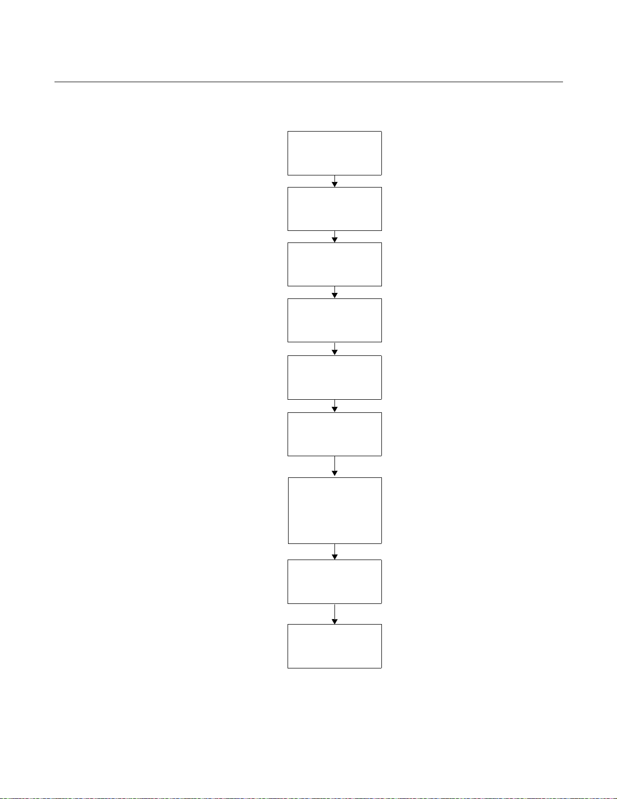
BEFORE YOU INSTALL Follow these steps for proper installation:
Review Installation
Considerations
(see page 2-4)
Check Processor
Switches
(See page 2-22)
Review Electrical
Considerations
(See page 2-24)
Mount Gauge
(See page 2-21)
Wire Gauge
(See page 2-22)
Wire Optional Devices
(See page 2-29)
Make sure covers and
conduit connections
are tight; plug unused
conduit entry
Power Up Gauge
(See page 2-33)
Configure Gauge
(See page 3-1)
2-3

Reference Manual
00809-0100-4731, Rev FA
APEX™and APEX Sentry™ Radar Gauge
April 2003
CONSIDERATIONS This section includes information you should consider before installing the
APEX and APEX Sentry Radar Gauges in the field. It includes information on
the following:
• Telecommunications agency requirements
• Unpacking the gauge
• Mounting requirements
• Vessel and process characteristics to consider
For information about configuring the radar gauge using a HART
Communicator, refer to Section 3: Configuration.
Telecommunications
Agency Requirements
Rosemount APEX and APEX Sentry Radar Gauges have been approved for
installation in closed metal tanks, including those that are vented to the
atmosphere. (See "Tank Requirements" below.) Tanks must be closed (or
vented) to contain radar emissions which can otherwise interfere with
aeronautical aviation. Installation shall be done by trained installers. The
radar gauges must be securely bolted to a standard tank flange in strict
compliance with the manufacturer’s instructions.
Failure to properly install the device could constitute an impermissible
modification of the device. In such an event, the responsibility is placed on the
modifying party to ensure compliance with telecommunications regulations,
and Rosemount shall have no liability whatsoever resulting from unauthorized
installation of the device.
Operation Requirements
The use of this device is on a “no-protection, no-interference” basis. That is,
the user shall accept government operations of high-powered radar in the
same frequency band which may interfere with or
damage this device. On the other hand, devices found to interfere
with Government operations will be required to be removed at the user’s
expense.
APEX and APEX Sentry Radar Gauges installed in the United Kingdom
operate between 24.15-26.05 GHz. All other APEX and APEX Sentry Radar
Gauges operate between 24.05 GHz and 26.05 GHz.
In certain countries, the radar gauge must be switched off when opening the
access door to the tank. Any usage in tanks made of non-metallic materials is
prohibited.
2-4
Underground tanks with all exposed surfaces metallized are sufficient to
contain radar emissions.
Tank Requirements
In the United States only, APEX and APEX Sentry Radar Gauges may also
be installed on enclosed or vented concrete tanks with a minimum wall
thickness of 2.5 inches.
In purchasing an APEX or APEX Sentry Radar Gauge, you agree to install the
device in accordance with these conditions.
At the time of this printing, Rosemount Inc. has received the appropriate
telecommunications approval for sale in the countries shown on page A-13.
If you have any questions about what constitutes proper installation, please
contact Rosemount Customer Central at 1-800-999-9307.
Reference Manual
00809-0100-4731, Rev FA
April 2003
APEX™and APEX Sentry™ Radar Gauge
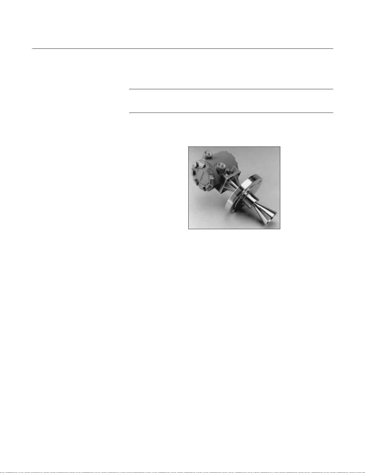
Unpacking the APEX and
APEX Sentry Radar
Gauges
Figure 2-1. APEX Radar Gauge
1. Remove the gauge from the shipping container, taking care not to
damage the contents.
2. Place the gauge on its side on a flat surface as in Figure 2-1.
NOTE
Do not stand the radar gauge upright on its antenna. Be careful not to
damage any part of the antenna during bench inspection or installation.
3. Inspect the unit and report any shipping damage to the carrier.
RADAR-003AB
Installation
Considerations
Before you install an APEX or APEX Sentry Radar Gauge, be sure to
consider your specific mounting requirements, vessel characteristics, and
process characteristics. Review the following information to ensure a
trouble-free, safe, and accurate installation.
The gauge has an Installation Category II (Overvoltage Category) with
pollution degree 2 classification.
Process Characteristics Dielectric Constant
Dielectric constant is a measure of a material’s ability to reflect a radar signal.
Materials with dielectric constants below 3.0 reflect only a small fraction of the
radar signal. Therefore, special care must be taken when measuring low
dielectric fluids.
The gauge can measure fluids with a dielectric constant as low as 1.8 if
vessel conditions are favorable. For example, water-based compounds tend
to have high dielectrics (water has a dielectric of approximately 80), while
hydrocarbons are low. In cases with low dielectrics, it is important to verify
that the dielectric is high enough for radar to measure. For information on
dielectric constants when using an APEX Radar Gauge, refer to Table 2-1 on
page 2-6. If you are unable to determine the dielectric constant for your
process, or if you are measuring a process with a dielectric constant lower
than 3.0, contact Rosemount Customer Central at 1-800-999-9307 for
assistance.
2-5

Reference Manual
00809-0100-4731, Rev FA
APEX™and APEX Sentry™ Radar Gauge
Table 2-1. Sample list of dielectric constants
Dielectric Constant Ranges for Chemicals Listed
Less Than 1.8 1.8 to 4.0 4.0 to 10.0 10.0 to 15.0 15.0 to 20.0 More than 20.0
carbon dioxide acetylene acetic acid benzyl alcohol ammonia acetone
cyclopentane asphalt bromobutane butyl nitrate butanol ethanol
ethylene benzene butyl alcohol carveol cyclohexanol ethylene glycol
methane butane chlorobenzene creosol diacetone alcohol glycerine
jp4 (military fuel) carbon tetrachloride chloroform dimethyl oxalate dichloro ethane glycol
propane cocaine chlorotoluene ethylene chloride isopropyl alcohol hydrazine
freons cresol hexanol lactic acid hydrogen peroxide
kerosene dibutyl phtalate iodine methylamine hydrogen cyanide
napthalene dichlorobutane methylamine methyl ethyl ketone latex
octane ethylamine phenol nitroglycerin methanol
oleic acid nicotine pyridine sulfur dioxide molasses
petroleum oils phosphorus tripropyl phosphate propanol
stearic acid phosgene vinyl isocyanate sorbitol
styrene sulfur water
sulfur toluene diisocyanate
toluene
vegetable oils
April 2003
Foam and Vapors
Foam may affect the gauge performance because it can reduce the radar
signal being reflected. The effect is highly dependent on the particular
characteristics of the foam. In general, the APEX Radar Gauge reads the top
of the foam if it is sufficiently reflective. The APEX Sentry Radar Gauge is not
for use in applications with foam.
Changing Density, Temperature, or Pressure
The level accuracy is not affected by changes in the density, temperature, or
pressure of the product.
Turbulence or Vortices
The gauge uses advanced signal processing, reducing the effects of
turbulence and vortices. However, the greater the turbulence or vortex the
larger the effect because they disturb the product surface where the signal is
being reflected. With vortices caused by agitators, you need to be aware of
the “swell” effect. That is, the product surface will rise in the vessel when
sufficiently agitated and the radar output will measure this rise. The APEX
Sentry Radar Gauge is not for use in turbulent applications. Refer to Figure
2-18 on page 2-22 for further information.
2-6
Reference Manual
00809-0100-4731, Rev FA
April 2003
APEX™and APEX Sentry™ Radar Gauge
Coating, Condensate, or Corrosion
The functionality of the gauge may be affected by coating, condensate, or
corrosion, depending on the type of process in the vessel. When conditions
produce heavy condensation or coating, or when the process is corrosive to
316 SST or alumina ceramic, Rosemount suggests using a process “window”
with the gauge to protect the antenna and waveguide.
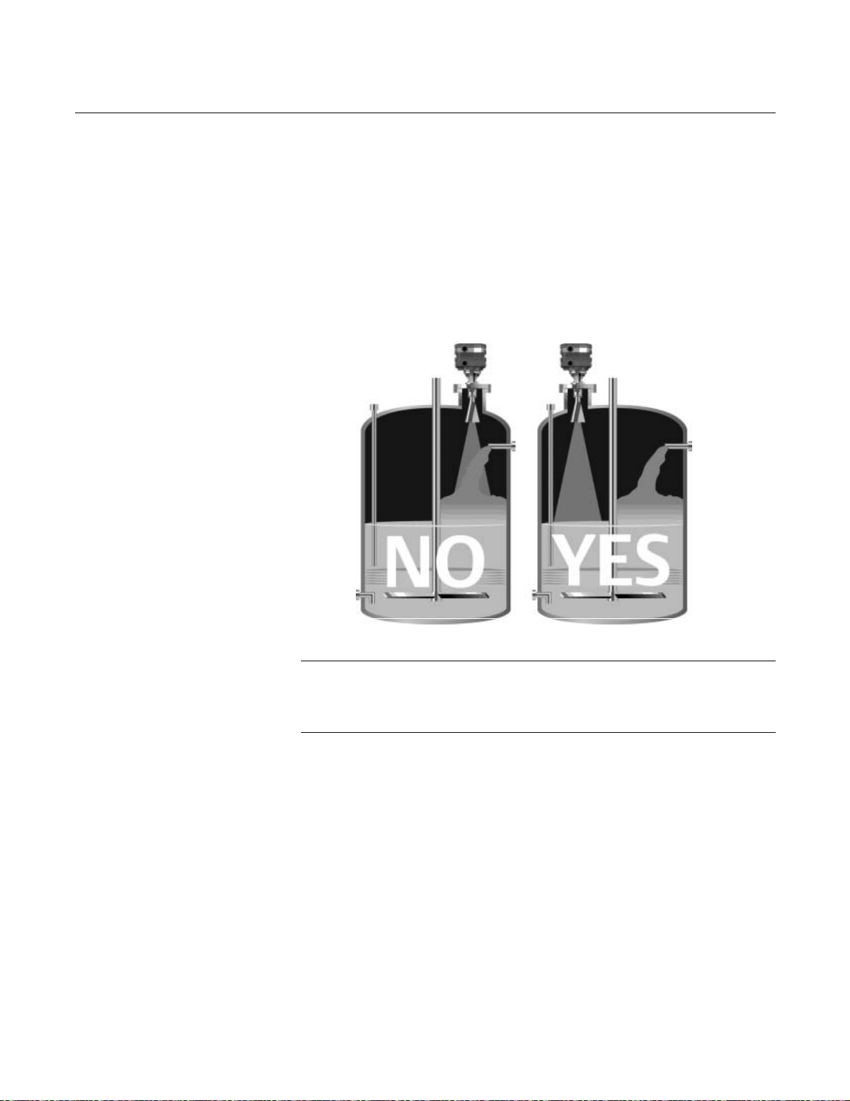
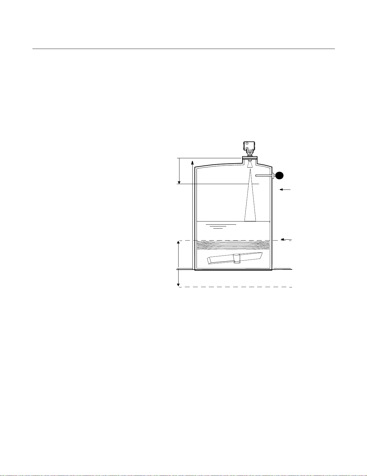
VESSEL CHARACTERISTICS
Figure 2-2. Vessel
Characteristics That May Affect
the Level Reading
Mount the gauge where it will have a clear view of the tank surface, but not in
the top center of the vessel (Figure 2-10).
LEVEL-SEETHEPROCESS.TIF
POOR PLACEMENT PREFERRED PLACEMENT
NOTE
When using an APEX Sentry Radar Gauge, it is necessary for 100% of the
beam cone to contact the liquid surface.
Refer to Table 2-2 on page 2-8 for further information.
2-7

APEX™and APEX Sentry™ Radar Gauge
Table 2-2. Beamwidth versus
Distance from flange face
to tank bottom
Distance (D)
from gauge
2-in. Antenna 3-in. Antenna 4-in. Antenna
ft (m) ft (m) ft (m) ft (m)
2 (0.6) 0.4 (0.12) 0.2 (0.07) 0.2 (0.06)
4 (1.2) 0.8 (0.25) 0.5 (0.15) 0.4 (0.11)
6 (1.8) 1.2 (0.37) 0.7 (0.22) 0.6 (0.17)
8 (2.4) 1.6 (0.49) 1.0 (0.29) 0.7 (0.22)
10 (3.0) 2.0 (0.62) 1.2 (0.37) 0.9 (0.28)
15 (4.6) 3.0 (0.93) 1.8 (0.55) 1.4 (0.42)
20 (6.1) 4.1 (1.23) 2.4 (0.73) 1.8 (0.56)
25 (7.6) 5.1 (1.54) 3.0 (0.92) 2.3 (0.70)
30 (9.1) 6.1 (1.85) 3.6 (1.10) 2.8 (0.84)
35 (10.7) 7.1 (2.16) 4.2 (1.28) 3.2 (0.98)
40 (12.2) 8.1 (2.47) 4.8 (1.46) 3.7 (1.12)
45 (13.7) 9.1 (2.78) 5.4 (1.65) 4.1 (1.26)
50 (15.2) 10.1 (3.09) 6.0 (1.83) 4.6 (1.40)
55 (16.8) 11.1 (3.40) 6.6 (2.01) 5.1 (1.54)
60 (18.3) 12.2 (3.70) 7.2 (2.20) 5.5 (1.68)
65 (19.8) 13.2 (4.01) 7.8 (2.38) 6.0 (1.82)
70 (21.3) 14.2 (4.32) 8.4 (2.56) 6.4 (1.96)
75 (22.9) 15.2 (4.63) 9.0 (2.75) 6.9 (2.10)
80 (24.4) 16.2 (4.94) 9.6 (2.93) 7.4 (2.24)
85 (25.9) 17.2 (5.25) 10.2 (3.11) 7.8 (2.38)
90 (27.4) 18.2 (5.56) 10.8 (3.30) 8.3 (2.52)
95 (29.0) 19.2 (5.86) 11.4 (3.48) 8.7 (2.66)
100 (30.5) 20.3 (6.17) 12.0 (3.66) 9.2 (2.80)
Radius (r) from Flange Centerline to
Reference Manual
00809-0100-4731, Rev FA
April 2003
Beamwidth Edge
2-8
Reference Manual
00809-0100-4731, Rev FA
April 2003
APEX™and APEX Sentry™ Radar Gauge
General Vessel
Considerations
Figure 2-3. User-Programmable
“Null” Zones for
APEX and APEX Sentry Radar
Gauges
Heating Coils and Agitators
If the vessel contains heating coils or agitators (see Figure 2-2), they may
create noise when the radar signal bounces off of them. The noise level is
less if the signal contacts a non-flat surface (for example, round pipe, angled
blade, etc.) that causes the signal to scatter rather than directing it back to the
antenna. To avoid these problems, try to make sure that heating coils or
agitators are below the minimum product level or within the null zones (see
Figure 2-3 on page 2-9 and Figure 2-3 on page 2-9).
Upper
Null
Zone
Radar gauge will not
measure above this line.
Reference
Gauge Height
High Level Switch
URV (20 mA)
LRV (4 mA)
Lower
Null
Zone
-19.6 in.
(-0.5 m)
Radar gauge will not measure below this line.
Reference Line
Cables, Floats, Baffles, or Trays
Cables, floats, baffles, or trays can introduce noise into the radar signal. A
vertical cable or rounded surface causes minimal effect because the radar
signal is scattered rather than directed back to the antenna. To reduce the
amount of noise from cables, floats, baffles, or trays, position the gauge such
that the beam will not contact them.
LEVEL-0579A
2-9
APEX™and APEX Sentry™ Radar Gauge
Inlet Pipes or Flows
The level reading may be affected by the process flowing into the vessel. To
lessen the effects, mount the radar gauge so the beam signal does not
contact the inlet pipe or flow (Figure 2-2).
Center of tank installations should be avoided, off-center installations are
preferred (Figure 2-4).
Figure 2-4. Example of off
center tank installation.
Reference Manual
00809-0100-4731, Rev FA
April 2003
NOTE
Center of the tank installations should be avoided.
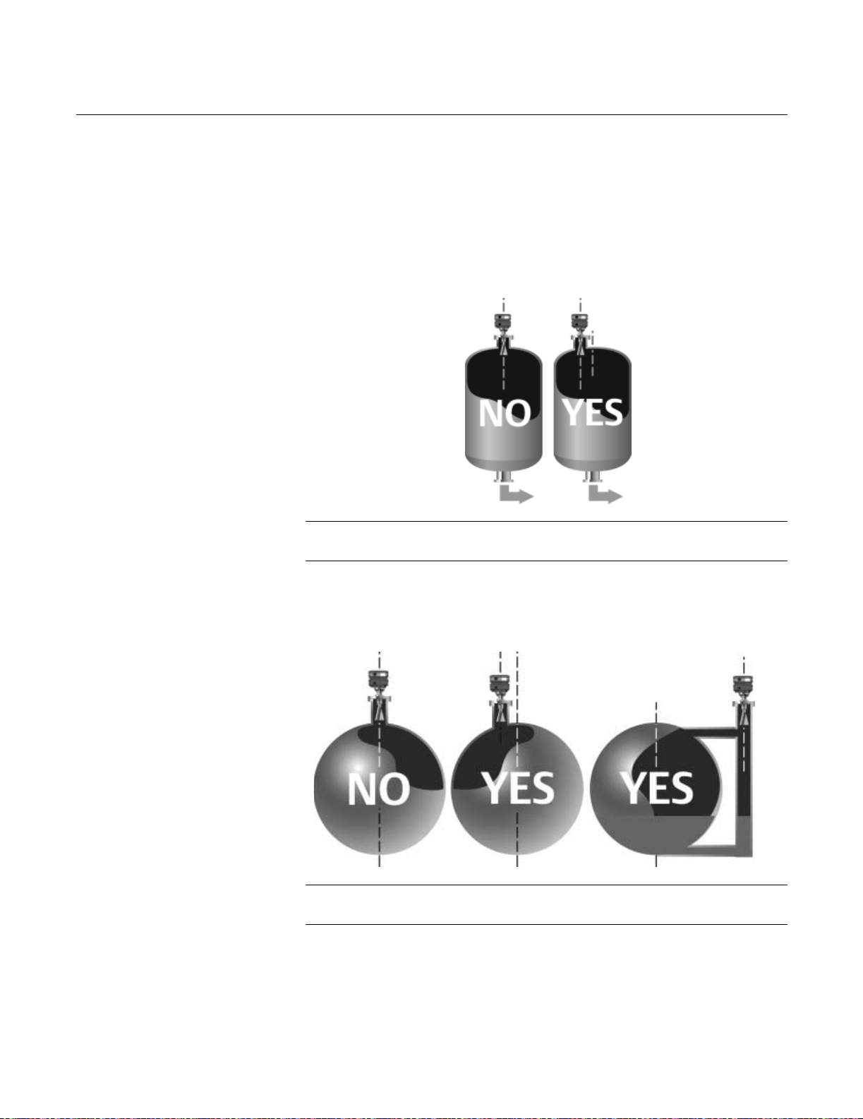
Specific Tank Shapes Spherical Vessel Considerations
Figure 2-5. Spherical vessel
installation
NOTE
Spheres should never have top-center installation options.
EXNEW/COLUMNALIGHN.TIF
SPHEREALIGN_AB.TIF
2-10
Reference Manual
00809-0100-4731, Rev FA
April 2003
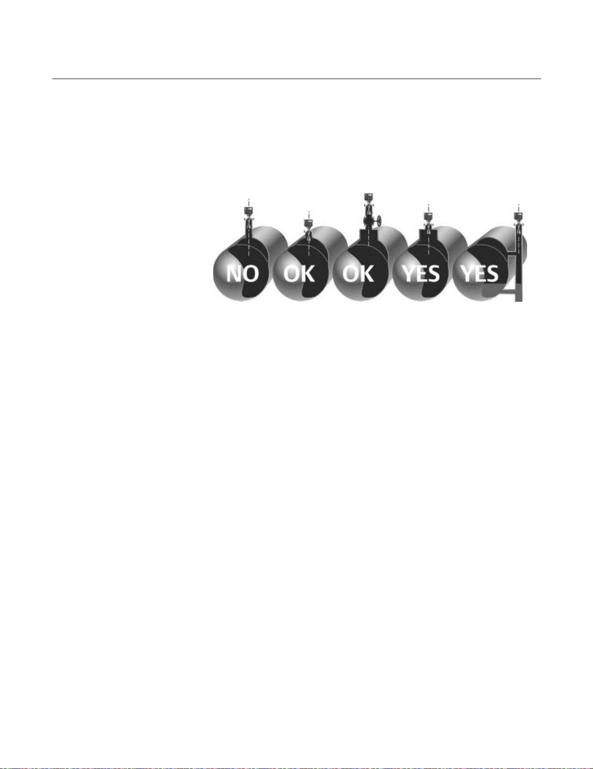
Figure 2-6. Possible horizontal
vessel mounting options
APEX™and APEX Sentry™ Radar Gauge
Horizontal Vessel Mounting Surface
Horizontal cylinders often only have top-center connection options. If this is
the case, then the end of the antenna should be down into the vessel or
mounted in a widened area such as a manhole cover. Recessing the antenna
into a nozzle is not recommended (Figure 2-6).
APEXNEW_CYLINDERS.TIF
2-11

APEX™and APEX Sentry™ Radar Gauge
Stilling Well, Bypass Cage, and
Bridle Connection Considerations
Apex and Apex Sentry can be mounted on bypass cages, bridles, and stilling
wells. Non-slotted stilling wells are preferred. If holes must be present, then 1
inch diameter holes approximately 0.5 meters apart are acceptable.
Higher dielectric materials (such as water-based compounds) in a stilling well
or bypass cage will create a strong return signal to the gauge. For this reason
smaller antennas should be used. Lower dielectric materials, (such as
hydrocarbons and solvents) will attenuate the signal so the antenna size
should be as large as possible for the bypass pipe or stilling well.
Figure 2-7. 3 inch or 4 inch
bypass cages can be used.
Reference Manual
00809-0100-4731, Rev FA
April 2003
20mA
4mA
BYPASSCONNECTIONS.TIF
• Stilling wells should be non-slotted. The signal will be stronger because
it is contained within the stilling well. With higher dielectric fluids it is
possible for the signal to be too strong. If this is the case, try using a
smaller antenna.
• At the low end of the well or bridle, especially with joints or bends in
pipes the level or distance may be incorrect due to false reflections. Fill
with fluid to cover the area.
2-12
Reference Manual
00809-0100-4731, Rev FA
April 2003
APEX™and APEX Sentry™ Radar Gauge
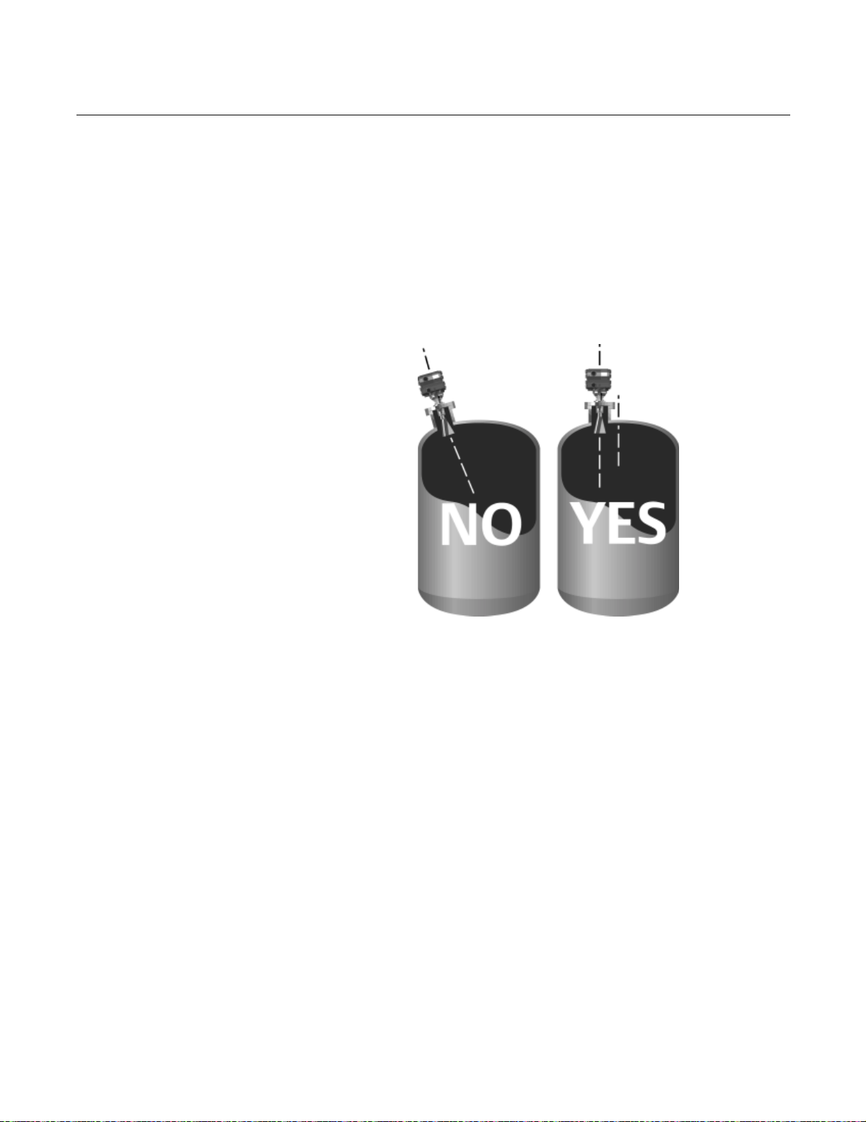
Nozzle Considerations Non-horizontal Mounting Surface
In most applications, the gauge should be mounted perpendicular to the level
surface. It is acceptable to have the mounting flange up to 2° off from
perpendicular. In applications with low dielectric constants or long measuring
ranges, mounting the radar gauge with the flange horizontal to the product
level becomes more important in order to receive an adequate return signal
(Vessel Characteristics on page 2-7). For more information regarding
mounting considerations, contact Rosemount Customer Central at
1-800-999-9307.
Figure 2-8. Example of
Non-horizontal mounting
APEXNEW/HORIZONTALMOUNTING.TIF
2-13
APEX™and APEX Sentry™ Radar Gauge
Tank Nozzle Considerations
Nozzles should be wide open and smooth without any intersecting lines. The
nozzles should not be too long because it will cause a reflection and attenuate
signal. Valves can be used as long as they are open and smooth (no
reducers, lips, or rough edges).
• Nozzles should be open and smooth; no weld lines or ledges should
protrude inside the nozzle, and there should be no restrictions.
• Maximum length of nozzle: 1m for 3 and 4 inch antennas, and 0.3m for
2 inch antennas.
• Full port valves may be used.
• The antenna can be recessed in the nozzle or can extend into the
vessel. However, the end of the antenna should never be even with the
roof of the tank (Figure 2-9).
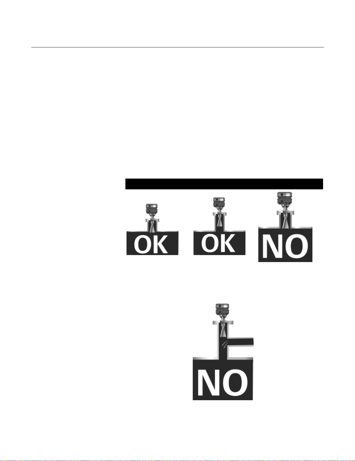
Figure 2-9. Tank Nozzle
Recommendation
Recommended Not Recommended
Reference Manual
00809-0100-4731, Rev FA
April 2003
Figure 2-10. Example of multiple
nozzle function
Note: Do not install an APEX
Radar Gauge where
there is a T-intersection in the
mounting nozzle.
Note: Antenna must not be even with the roof tank.
APEX_CONEALIGNBA.TIF
The gauge should be mounted so antenna extends 1 inch or more into the
tank, or is recessed into the nozzle by 1 inch or more.
APEX_CONEALIGN.TIF
GASPURGE_AB.TIF
2-14
 Loading...