

Manual: Rosemount 848T High Density Temperature Transmitter with FOUNDATION Fieldbus
Table of contents
 Loading...
Rosemount Manual: Rosemount 848T High Density Temperature Transmitter with FOUNDATION Fieldbus Manuals & Guides

Reference Manual
00809-0100-4697, Rev GB
January 2022
Rosemount™ 848T High Density Temperature
Transmitter with FOUNDATION™ Fieldbus

2

Reference Manual Contents
00809-0100-4697 January 2022
Contents
Chapter 1 Introduction.............................................................................................................. 5
1.1 Hazard messages.........................................................................................................................5
1.2 Safety messages.......................................................................................................................... 5
1.3 Product recycling/disposal...........................................................................................................7
Chapter 2 Installation.................................................................................................................9
2.1 Mounting ....................................................................................................................................9
2.2 Wiring........................................................................................................................................16
2.3 Grounding................................................................................................................................. 20
2.4 Switches.................................................................................................................................... 23
2.5 Tagging..................................................................................................................................... 23
2.6 Installation ................................................................................................................................24
Chapter 3 Configuration...........................................................................................................27
3.1 Standard configuration..............................................................................................................27
3.2 Transmitter configuration..........................................................................................................27
3.3 Custom configuration................................................................................................................27
3.4 Configure methods....................................................................................................................28
3.5 Configure alarms....................................................................................................................... 28
3.6 Configure damping....................................................................................................................28
3.7 Configure the differential sensors.............................................................................................. 28
3.8 Configure measurement validation............................................................................................29
3.9 Common configurations for high density applications...............................................................29
3.10 Configure blocks......................................................................................................................33
Chapter 4 Operation and maintenance.....................................................................................61
4.1 FOUNDATION Fieldbus information...............................................................................................61
4.2 Hardware maintenance............................................................................................................. 61
4.3 Troubleshooting........................................................................................................................62
Appendix A Reference data......................................................................................................... 65
A.1 Functional specifications........................................................................................................... 65
A.2 Physical specifications............................................................................................................... 66
A.3 Function blocks......................................................................................................................... 67
A.4 Performance specifications........................................................................................................68
A.5 Dimensional drawings for Rosemount 848T FOUNDATION Fieldbus..............................................72
A.6 Ordering information................................................................................................................ 79
Appendix B Product certifications............................................................................................... 83
B.1 European Directive Information.................................................................................................83
B.2 Ordinary Location Certification.................................................................................................. 83
Emerson.com/Rosemount 3

Contents Reference Manual
January 2022 00809-0100-4697
B.3 North America........................................................................................................................... 83
B.4 USA............................................................................................................................................83
B.5 Canada...................................................................................................................................... 84
B.6 Europe.......................................................................................................................................85
B.7 International..............................................................................................................................87
B.8 Brazil..........................................................................................................................................89
B.9 China......................................................................................................................................... 90
B.10 Japan....................................................................................................................................... 92
B.11 Korea.......................................................................................................................................92
B.12 EAC - Belarus, Kazakhstan, Russia.............................................................................................93
B.13 Combinations..........................................................................................................................93
B.14 Conduit Plugs and Adapters.....................................................................................................93
B.15 Additional Certifications.......................................................................................................... 94
B.16 Intrinsically Safe and Non-Incendive installations.....................................................................95
B.17 Installation drawings................................................................................................................96
Appendix C FOUNDATION Fieldbus technology......................................................................... 105
C.1 Overview................................................................................................................................. 105
C.2 Function blocks....................................................................................................................... 105
C.3 Device descriptions................................................................................................................. 106
C.4 Block operation....................................................................................................................... 107
C.5 Network communication.........................................................................................................107
Appendix D Function blocks......................................................................................................113
D.1 Analog Input (AI) function block..............................................................................................113
D.2 Multiple analog input (MAI) function block..............................................................................122
D.3 Input selector function block...................................................................................................129
4 Emerson.com/Rosemount

Reference Manual
00809-0100-4697 January 2022
Introduction
1 Introduction
The Rosemount 848T is optimized for process temperature measurement because it can simultaneously
measure eight separate and independent temperature points with one transmitter. You can connect multiple
temperature sensor types to each transmitter. In addition, the Rosemount 848T can accept 4-20 mA inputs.
The enhanced measurement capability of the Rosemount 848T allows it to communicate these variables to
any FOUNDATION™ Fieldbus host or configuration tool.
1.1 Hazard messages
This document uses the following criteria for hazard messages based on ANSI standards Z535.6-2011
(R2017).
DANGER
Serious injury or death will occur if a hazardous situation is not avoided.
WARNING
Serious injury or death could occur if a hazardous situation is not avoided.
CAUTION
Minor or moderate injury will or could occur if a hazardous situation is not avoided.
NOTICE
Data loss, property damage, hardware damage, or software damage can occur if a situation is not avoided.
There is no credible risk of physical injury.
Physical access
NOTICE
Unauthorized personnel can potentially cause significant damage and/or misconfiguration of end users'
equipment. Protect against all intentional or unintentional unauthorized use.
Physical security is an important part of any security program and fundamental to protecting your system.
Restrict physical access to protect users' assets. This is true for all systems used within the facility.
1.2 Safety messages
Read this manual before working with the product. For personal and system safety, and for optimum product
performance, ensure you thoroughly understand the contents before installing, using, or maintaining this
product.
Emerson.com/Rosemount 5

Introduction Reference Manual
January 2022 00809-0100-4697
WARNING
Explosions could result in death or serious injury.
Installation of this transmitter in an explosive environment must be in accordance with the appropriate local,
national, and international standards, codes, and practices. Review the approvals section of this manual for
any restrictions associated with a safe installation.
Before connecting a Field Communicator in an explosive atmosphere, make sure the instruments in the loop
are installed in accordance with intrinsically safe or non-incendive field wiring practices.
WARNING
Failure to follow these installation guidelines could result in death or serious injury.
Ensure the transmitter is installed by qualified personnel and in accordance with applicable code of practice.
WARNING
Process leaks could result in death or serious injury.
Do not remove the thermowell while in operation.
Install and tighten thermowells and sensors before applying pressure.
WARNING
Electrical shock could cause death or serious injury.
If the sensor is installed in a high-voltage environment and a fault or installation error occurs, high voltage
may be present on transmitter leads and terminals.
Use extreme caution when making contact with the leads and terminals.
CAUTION
This device complies with Part 15 of the FCC Rules. Operation is subject to the following conditions:
• This device may not cause harmful interference.
• This device must accept any interference received, including interference that may cause undesired
operation.
• This device must be installed to ensure a minimum antenna separation distance of 7.9 in. (20 cm) from all
persons.
6 Emerson.com/Rosemount

Reference Manual Introduction
00809-0100-4697 January 2022
NOTICE
Battery hazards remain when cells are discharged.
The power module may be replaced in a hazardous area. The power module has surface resistivity greater
than one gigaohm and must be properly installed in the wireless device enclosure. Care must be taken during
transportation to and from the point of installation to prevent electrostatic charge build-up.
Shipping considerations for wireless products.
• The unit was shipped to you without the power module installed. Remove the power module prior to any
re-shipping.
• Each power module contains two “C” size primary lithium batteries. Primary lithium batteries are
regulated in transportation by the U. S. Department of Transportation, and are also covered by IATA
(International Air Transport Association), ICAO (International Civil Aviation Organization), and ARD
(European Ground Transportation of Dangerous Goods). It is the responsibility of the shipper to ensure
compliance with these or any other local requirements. Consult current regulations and requirements
before shipping.
1.3 Product recycling/disposal
Recycling of equipment and packaging should be taken into consideration and disposed of in accordance with
local and national legislation/regulations.
Emerson.com/Rosemount 7

Introduction Reference Manual
January 2022 00809-0100-4697
8 Emerson.com/Rosemount
Reference Manual
00809-0100-4697 January 2022
Installation
2 Installation
2.1 Mounting
The transmitter is always mounted remote from the sensor assembly. There are three mounting
configurations as follows:
• To a DIN rail without an enclosure
• To a panel with an enclosure
• To a 2 in (51 mm) pipe stand with an enclosure using a pipe mounting kit
2.1.1 Mount to a DIN rail without an enclosure
To mount the transmitter to a DIN rail without an enclosure, follow these steps:
Procedure
1. Pull up the DIN rail mounting clip located on the top back side of the transmitter.
2. Hinge the DIN rail into the slots on the bottom of the transmitter.
3. Tilt the transmitter and place onto the DIN rail. Release the mounting clip. The transmitter should be
securely fastened to the DIN rail.
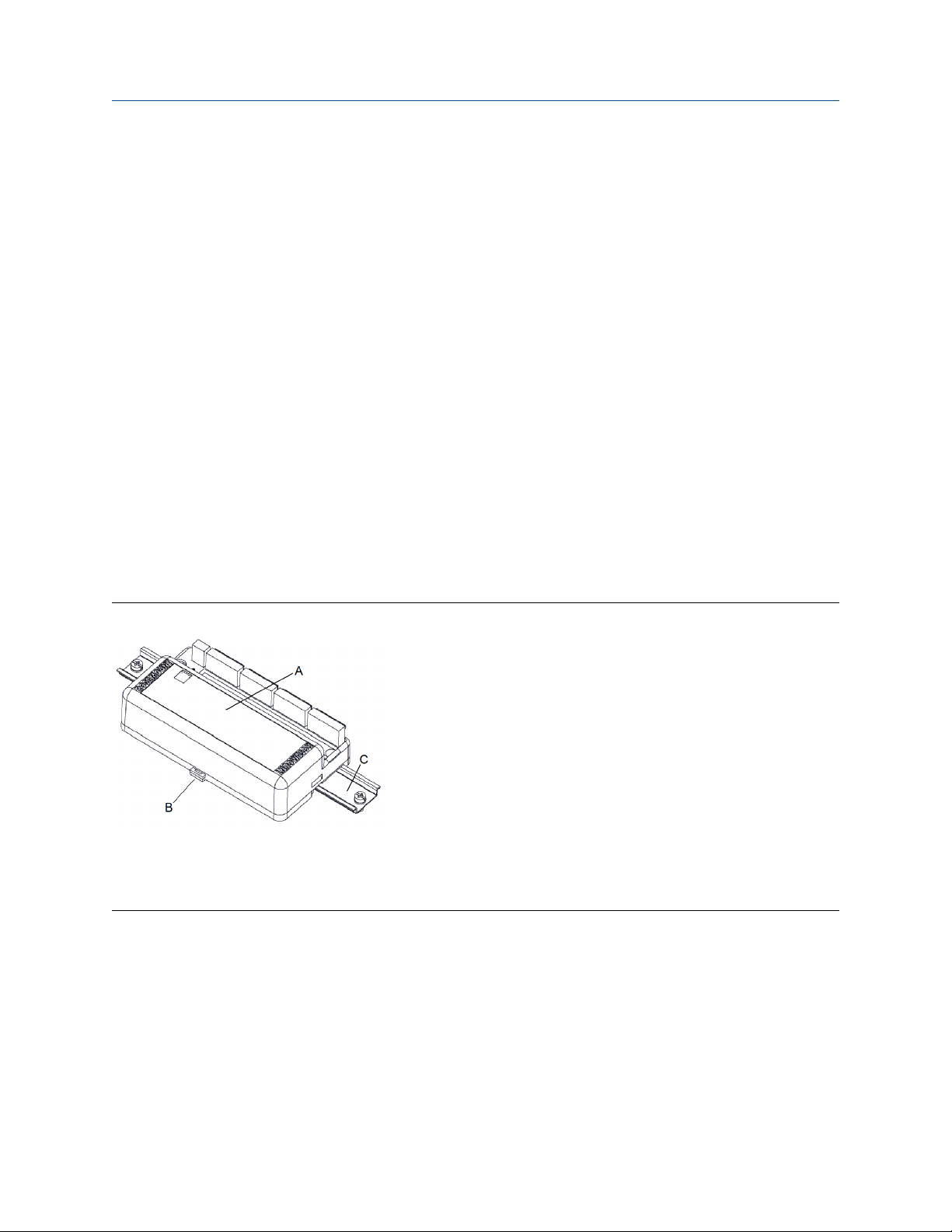
Figure 2-1: Mount the transmitter to a DIN rail
A. Rosemount 848T without installed enclosure
B. DIN rail mounting clip
C. DIN rail
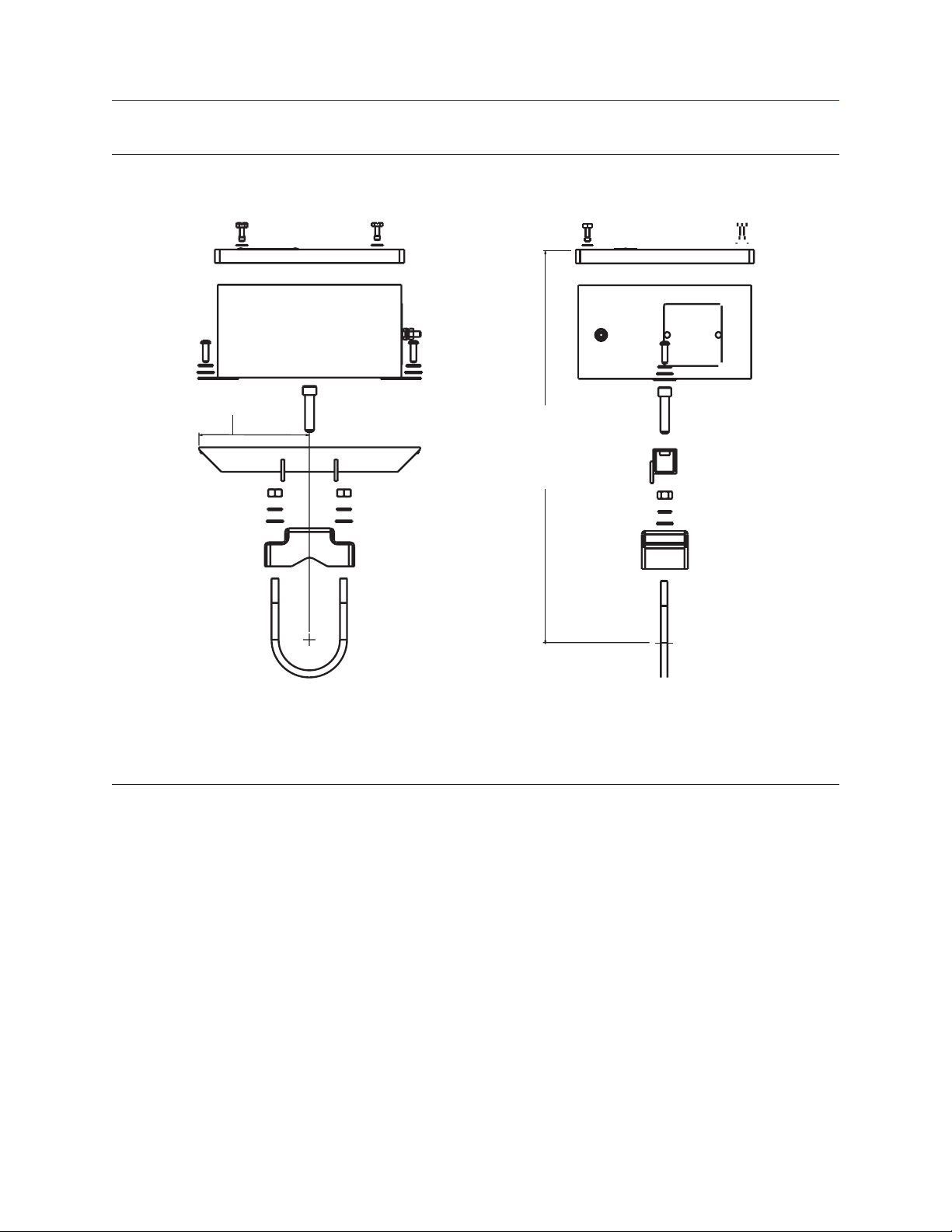
2.1.2 Mount to a panel from an aluminum junction box
Prerequisites
Use four 1/4-20 x 1.25-in. screws.
Procedure
Mount the transmitter to a panel from inside the junction box using one of the following dimension drawings.
Emerson.com/Rosemount 9

10.21
[259]
A
1.70
[43]
B
6.70
[170]
C
D
3.67
[93]
E
.80
[20]
2.30
[58]
2.27
[58]
1.33
[34]
1.88
[48]
3.98
[101]
8.42
[214]
6.00
[152]
Installation Reference Manual
January 2022 00809-0100-4697
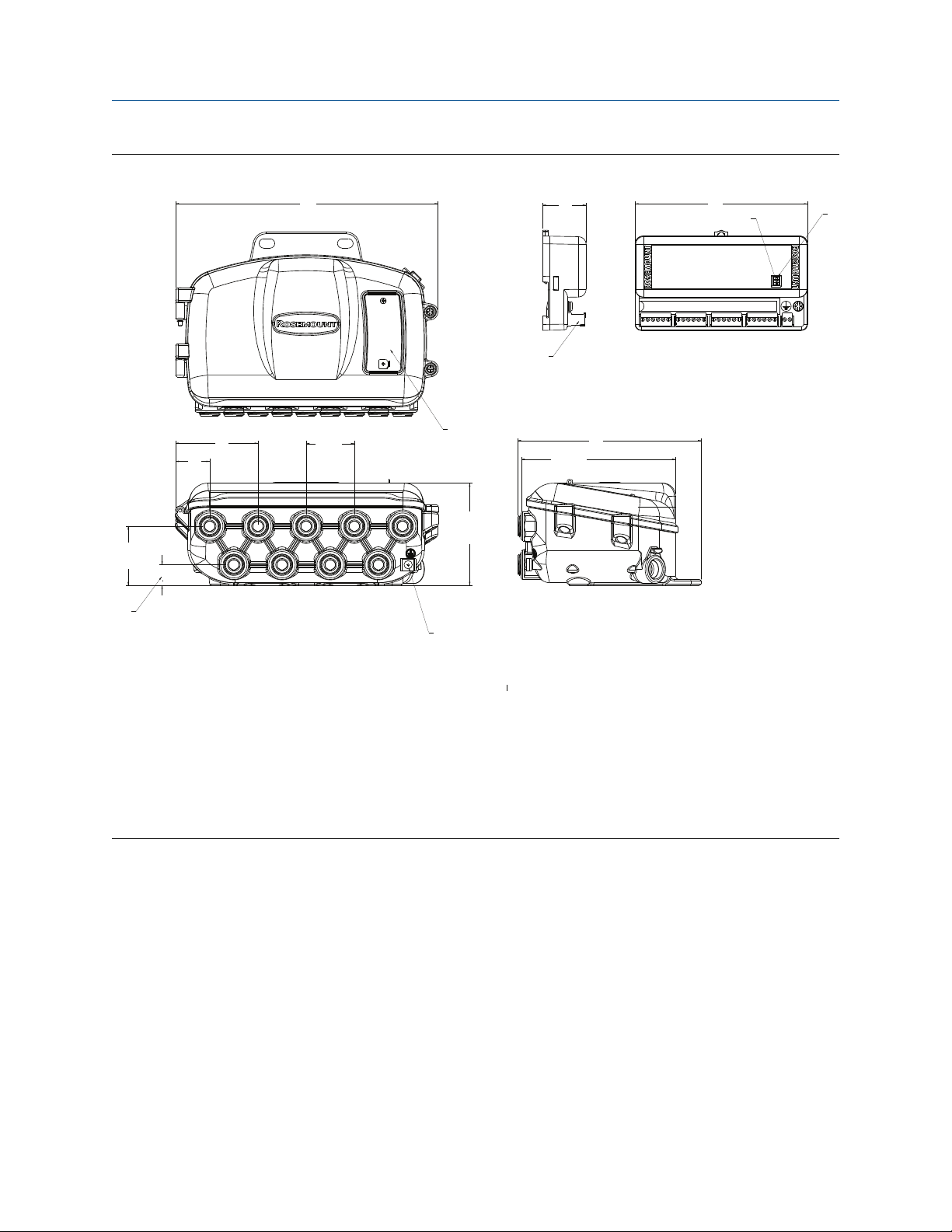
Figure 2-2: Aluminum junction box with cable glands (option code JA4)
A. Nameplate
B. Removable wiring connector
C. Security switch
D. Simulation switch
E. External ground screw (optional)
Dimensions are in inches (millimeters).
10 Emerson.com/Rosemount
A
10.21
[259]
1.70
[43]
B
6.70
[170]
C
D
.80
[20]
2.30
[58]
3.21
[81]
1.33
[34]
1.88
[48]
3.97
[101]
E
7.14
[181]
6.00
[152]
Reference Manual Installation
00809-0100-4697 January 2022
Figure 2-3: Aluminum junction box with plugged holes (option code JA5)
A. Nameplate
B. Removable wiring connection
C. Security switch
D. Simulation switch
E. External ground screw (optional)
Dimensions are in inches (millimeters).
2.1.3 Mount to a panel from a stainless steel junction box
Prerequisites
Use two 1/4-20 x 1/2-in. screws.
Procedure
Mount the transmitter to a panel from inside the junction box using one of the following dimension drawings.
Emerson.com/Rosemount 11
9.91 (231)
7.7 (196)
C
1.8 (46)
1.1 (28)
1.73 (44)
2.4 (62)
1.2 (30)
1.8 (47)
4.0 (102)
9.14 (232.2)
7.72 (196)
6.61 (168)
A B
D E
Installation Reference Manual
January 2022 00809-0100-4697
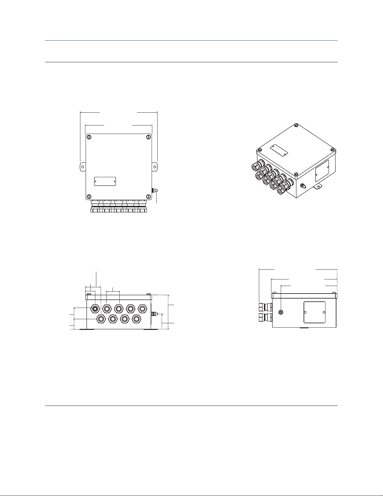
Figure 2-4: Stainless steel junction box with cable glands (option code JS2)
A. Top view
B. 3-D view
C. Ground screw
D. Front view
E. Side view
Dimensions are in inches (millimeters).
12 Emerson.com/Rosemount
9.1 (231)
7.7 (196)
C
A
4.0 (102)
B
1.4 (35)
1.1 (27)
2.8 (70)
4.0 (102)
1.8 (4.7)
2.4 (62)
1.6 (42)
F
D
1.2 (30)
E
Reference Manual Installation
00809-0100-4697 January 2022
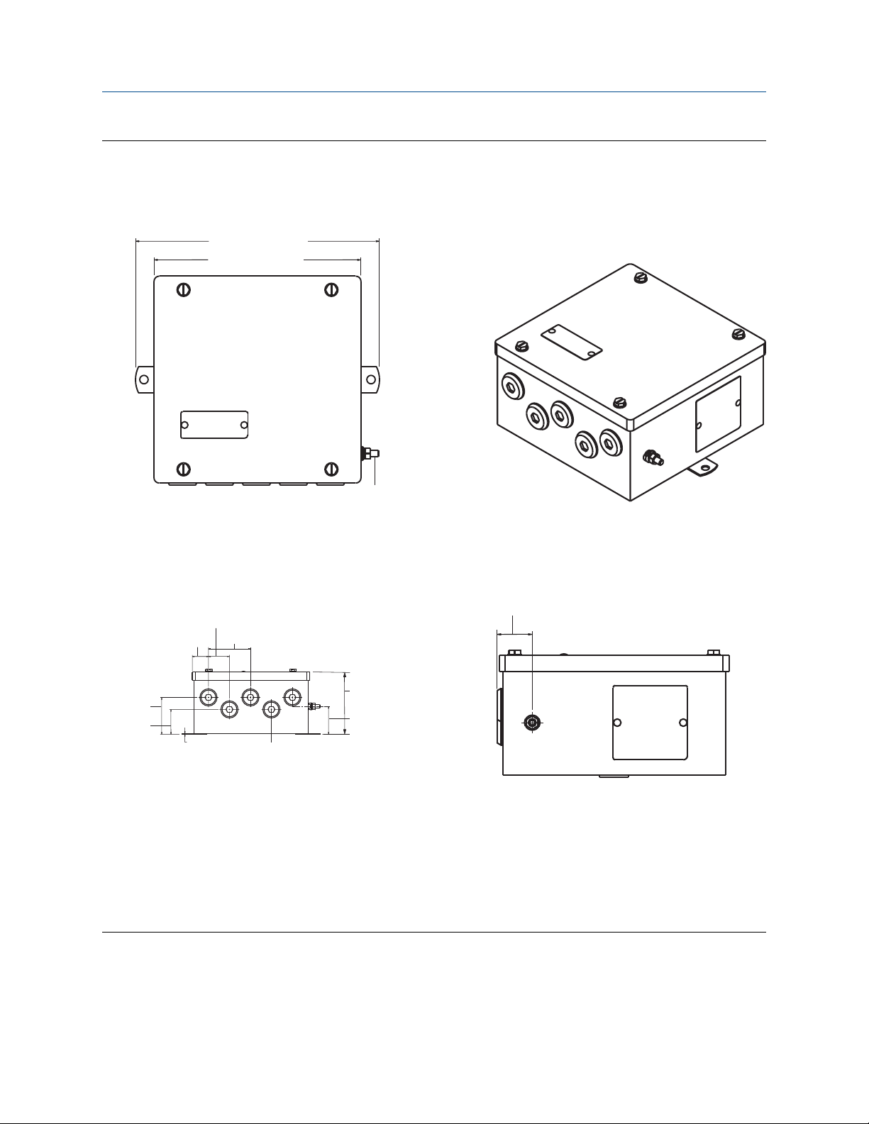
Figure 2-5: Stainless steel junction box with a conduit entry (option code JS3)
A. Top view
B. 3-D view
C. Ground screw
D. Front view
E. Side view
F. Five plugged 0.86 in (21.8 mm) diameter holes suitable for installing ½-in. NPT fittings
Dimensions are in inches (millimeters).
Emerson.com/Rosemount 13

․
‥
A B
5.08
[129]
7.55
[193]
Installation Reference Manual
January 2022 00809-0100-4697
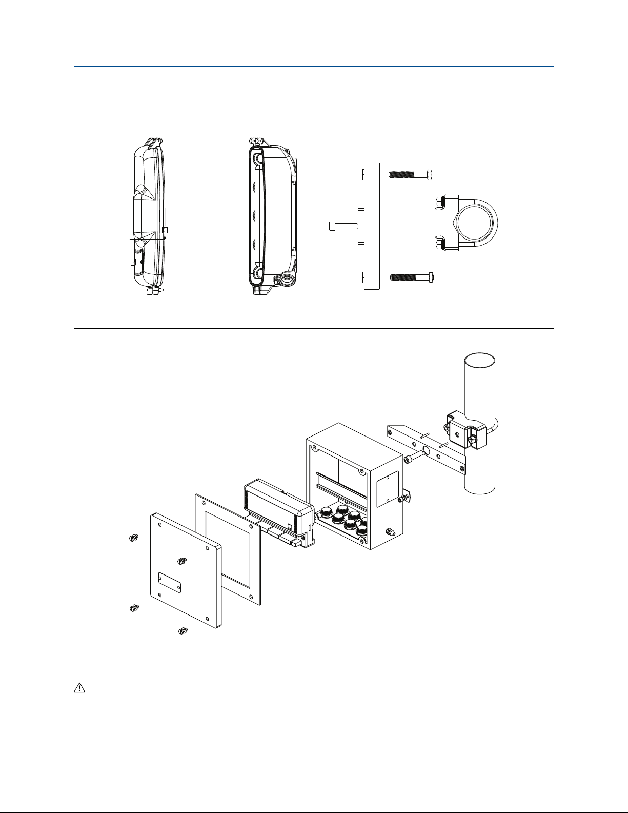
2.1.4 Mount to a 2 in (51 mm) pipe stand
Procedure
Use the optional mounting bracket (option code B6) to mount the transmitter to a 2 in (51 mm) pipe stand
when using a junction box.
Figure 2-6: Mount an aluminum junction box
A. Front view
B. Side view
Dimensions are in inches (millimeters)
14 Emerson.com/Rosemount
4.7 (119)
7.5 (190)
C
A B
Reference Manual Installation
00809-0100-4697 January 2022
Figure 2-7: Mount a stainless steel junction box
A. Front view
B. Side view
C. Fully assembled
Dimensions are in inches (millimeters)
Emerson.com/Rosemount 15
Installation
January 2022 00809-0100-4697
Figure 2-8: Mount aluminum on a vertical pipe
Figure 2-9: Mount stainless steel on vertical pipe
Reference Manual
2.2 Wiring
If the sensor is installed in a high-voltage environment and a fault condition or installation error occurs, the
sensor leads and transmitter terminals could carry lethal voltages. Use extreme caution when making contact
with the leads and terminals.
16 Emerson.com/Rosemount
%
$
&
)
)
*
+
'
(
Reference Manual
Installation
00809-0100-4697 January 2022
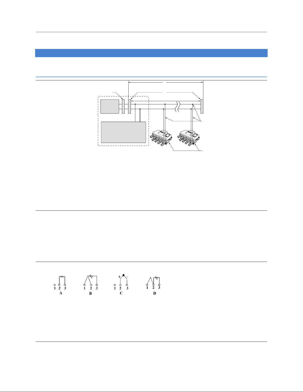
NOTICE
Do not apply high voltage (e.g. AC line voltage) to the transmitter terminals. Abnormally high voltage can
damage the unit (bus terminals are rated to 42.4 VDC).
A. Integrated power conditioner and filter
B. 6234 ft. (1900 m) max (depending upon cable characteristics)
C. Terminators (trunk)
D. Power supply
E. FOUNDATION Fieldbus host or configuration tool
F. Spurs
G. Signal wiring
H. Devices 1-16 (intrinsically safe installations may allow fewer devices per I.S. barrier)
2.2.1 Connections
The Rosemount 848T transmitter is compatible with 2 or 3-wire RTD, thermocouple, ohm, and millivolt
sensor types. Figure 2-10 shows the correct input connections to the sensor terminals on the transmitter. The
Rosemount 848T can also accept inputs from analog devices using the optional analog input connector.
Figure 2-11 shows the correct input connections to the analog input connector when installed on the
transmitter. Tighten the terminal screws to ensure proper connection.
Figure 2-10: Sensor wiring diagram
A. 2-wire RTD and ohms
B. 3-wire RTD and ohms (Emerson provides 4-wire sensors for all single-element RTDs; use these RTDs in 3-wire
configurations by clipping the fourth lead or leaving it disconnected and insulated with electrical tape.)
C. Thermocouples/ohms and millivolts
D. 2-wire RTD with compensation loop (transmitter must be configured for a 3-wire RTD in order to recognize
an RTD with a compensation loop)
Emerson.com/Rosemount 17

Installation Reference Manual
January 2022 00809-0100-4697
RTD or ohm inputs
Various RTD configurations, including 2-wire and 3-wire are used in industrial applications. If the transmitter is
mounted remotely from a 3-wire RTD, it will operate within specifications, without recalibration, for lead wire
resistances of up to 60 ohms per lead (equivalent to 6,000 ft (1,829 m) of 20 AWG (0.518 mm²) wire). If using
a 2-wire RTD, both RTD leads are in series with the sensor element, so errors can occur if the lead lengths
exceed one foot of 20 AWG (0.518 mm²) wire. Compensation for this error is provided when using 3-wire
RTDs.
Thermocouple or millivolt inputs
Use appropriate thermocouple extension wire to connect the thermocouple to the transmitter. Make
connections for millivolt inputs using copper wire. Use shielding for long runs of wire.
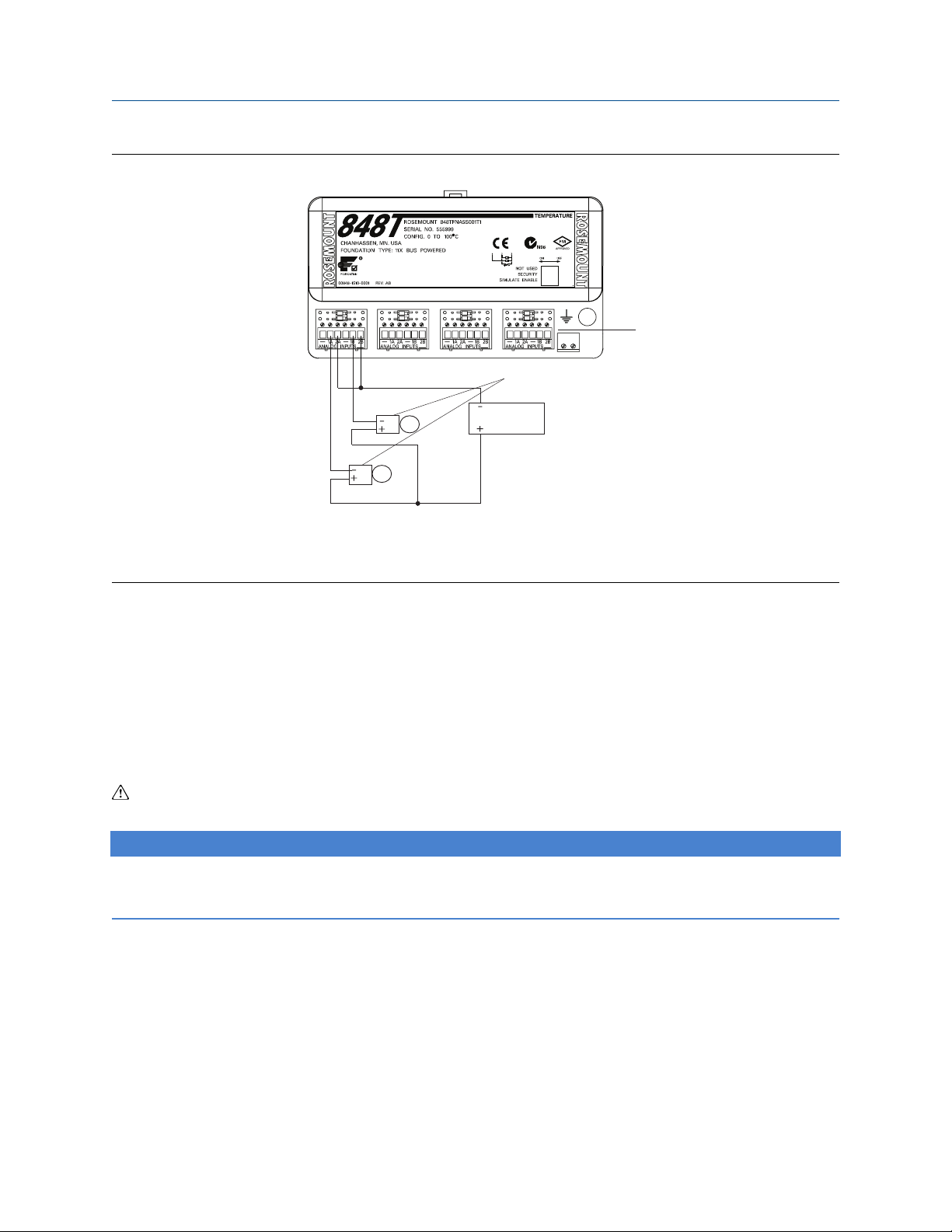
Analog inputs
The analog connector converts the 4–20 mA signal to a 20–100 mV signal that can be read by the transmitter
and transmitted using FOUNDATION Fieldbus.
Use the following steps when installing the transmitter with the analog connector:
Procedure
1. The Rosemount 848T, when ordered with option code S002, comes with four analog connectors.
Replace the standard connector with the analog connector on the desired channels.
2. Wire one or two analog transmitters to the analog connector according to Figure 2-11. There is space
available on the analog connector label for identification of the analog inputs.
Note
Power supply should be rated to support the connected transmitter(s).
3. If the analog transmitters can communicate using HART® protocol, the analog connectors are supplied
with the ability to switch in a 250 ohm resistor for HART communication (see Figure 2-11). One switch
is supplied for each input (top switch for A inputs and bottom switch for B inputs). Setting the switch in
the ON position (to the right) bypasses the 250 ohm resistor. Terminals are provided for each analog
input to connect a field communicator for local configuration.
18 Emerson.com/Rosemount
A
C
B
Reference Manual
00809-0100-4697 January 2022
Figure 2-11: Rosemount 848T Analog Input Wiring Diagram
Installation
A. Analog input connectors
B. Analog transmitters
C. Power supply
2.2.2 Power supply
Connect the power supply
The transmitter requires between 9 and 32 VDC to operate and provide complete functionality. The DC
power supply should provide power with less than 2% ripple. A fieldbus segment requires a power conditioner
to isolate the power supply filter and decouple the segment from other segments attached to the same
power supply.
All power to the transmitter is supplied over the signal wiring. Signal wiring should be shielded, twisted
pair for best results in electrically noisy environments.
NOTICE
For best performance, do not use unshielded signal wiring in open trays with power wiring or near heavy
electrical equipment.
Use ordinary copper wire of sufficient size to ensure the voltage across the transmitter power terminals does
not go below 9 VDC. The power terminals are polarity insensitive. To power the transmitter:
Procedure
1. Connect the power leads to the terminals marked Bus, as shown in Figure 2-12.
2. Tighten the terminal screws to ensure adequate contact. No additional power wiring is necessary.
Emerson.com/Rosemount 19
NOT USED
SECURITY
SIMULA
TE ENABLE
A
B
Installation
January 2022 00809-0100-4697
Figure 2-12: Transmitter label
A. Ground (required with T1 option)
B. Connect power leads here
Reference Manual
2.2.3 Surges/transients
The transmitter will withstand electrical transients encountered through static discharges or induced
switching transients. However, a transient protection option (option code T1) is available to protect the
transmitter against high-energy transients. The device must be properly grounded using the ground terminal
(see Figure 2-12).
2.3 Grounding
The Rosemount 848T transmitter provides input/output isolation up to 620 V rms.
NOTICE
Neither conductor of the fieldbus segment can be grounded. Grounding out one of the signal wires will shut
down the entire fieldbus segment.
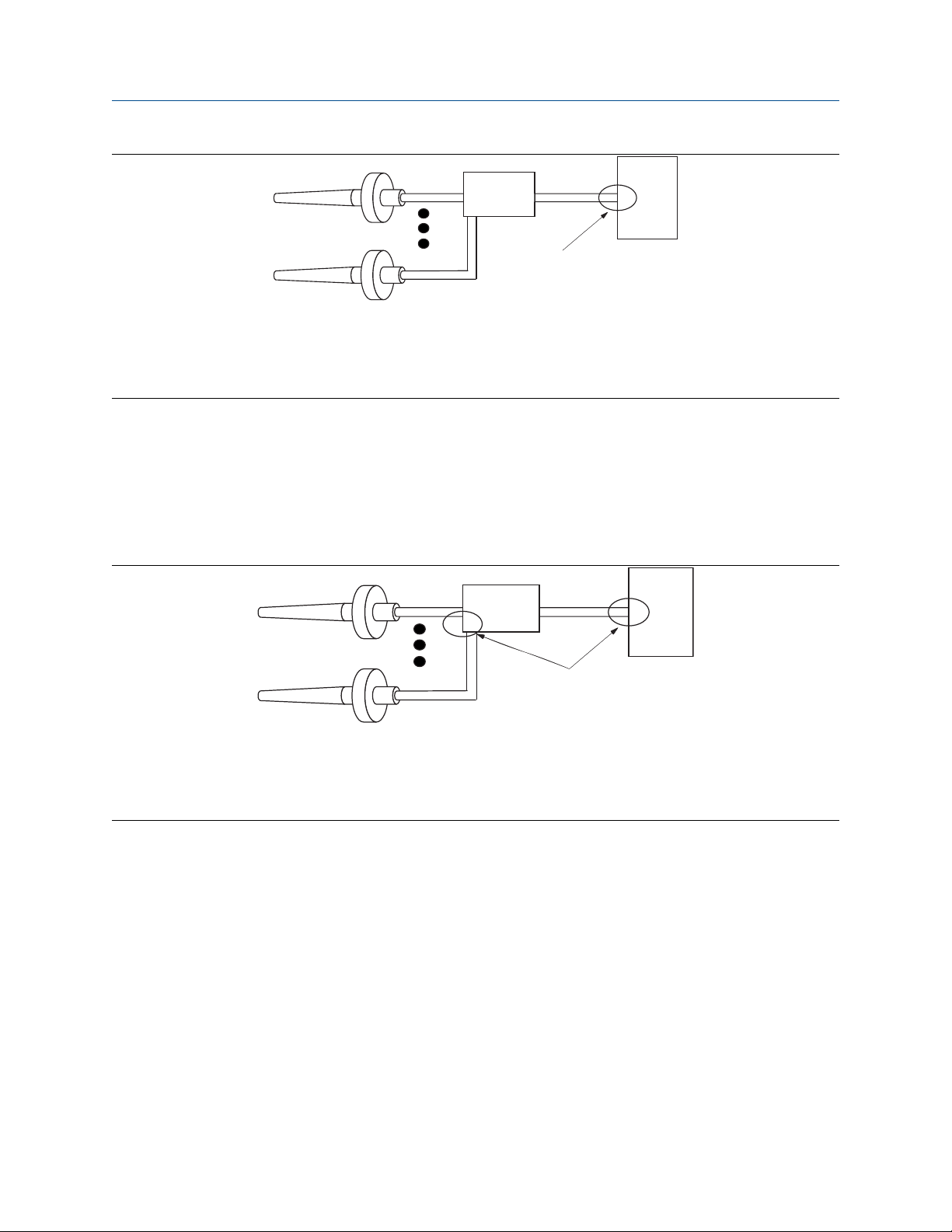
2.3.1 Shielded wire
Each process installation has different requirements for grounding. Use the grounding options recommended
by the facility for the specific sensor type or begin with grounding option 1 (most common).
Ungrounded thermocouple, mV, and RTD/ohm inputs
There are two options for ungrounded thermocouple, mV, and RTD/ohm inputs.
Option 1
Procedure
1. Connect signal wiring shield to the sensor wiring shield(s).
2. Ensure shields are tied together and electrically isolated from transmitter enclosure.
3. Only ground shield at the power supply end.
4. Ensure sensor shield(s) is electrically isolated from the surrounding grounded fixtures.
20 Emerson.com/Rosemount
A
B
C
D
A
B
C
D
Reference Manual
00809-0100-4697 January 2022
A. Sensor wires
B. Rosemount™ 848T
C. Power supply
D. Shield ground point
Installation
Option 2
Procedure
1. If the enclosure is grounded, connect sensor wiring shield(s) to the transmitter enclosure.
2. Ensure sensor shield(s) is electrically isolated from surrounding fixtures that may be grounded.
3. Ground signal wiring shield at the power supply end.
A. Sensor wires
B. Rosemount 848T
C. Power supply
D. Shield ground points
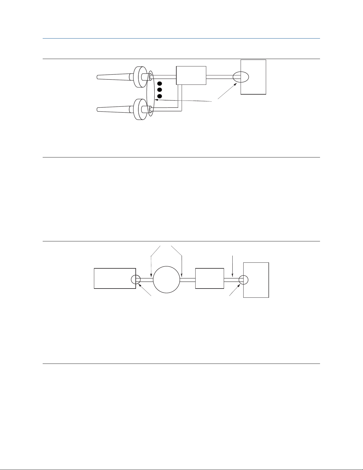
Grounded thermocouple inputs
Procedure
1. Ground sensor wiring shield(s) at the sensor.
2. Ensure that the sensor wiring and signal wiring shields are electrically isolated from the transmitter
enclosure.
3. Do not connect the signal wiring shield to the sensor wiring shield(s).
4. Ground signal wiring shield at the power supply end.
Emerson.com/Rosemount 21
A
B
C
D
C
D
A
E F
G
G
B
Installation
January 2022 00809-0100-4697
A. Sensor wires
B. Rosemount 848T
C. Power supply
D. Shield ground points
Reference Manual
Analog device inputs
Procedure
1. Ground analog signal wire at the power supply of the analog devices.
2. Ensure the analog signal wire and the fieldbus signal wire shields are electrically isolated from the
transmitter enclosure.
3. Do not connect the analog signal wire shield to the fieldbus signal wire shield.
4. Ground fieldbus signal wire shield at the power supply end.
A. 4-20 mA loop
B. FOUNDATION Fieldbus
C. Analog device power supply
D. Analog device
E. Rosemount 848T
F. Power supply
G. Shield ground points
2.3.2 Transmitter enclosure (optional)
Procedure
Ground the transmitter in accordance with local electrical requirements.
22 Emerson.com/Rosemount

NOT USED
SECURITY
SIMULATE ENABLE
Reference Manual Installation
00809-0100-4697 January 2022
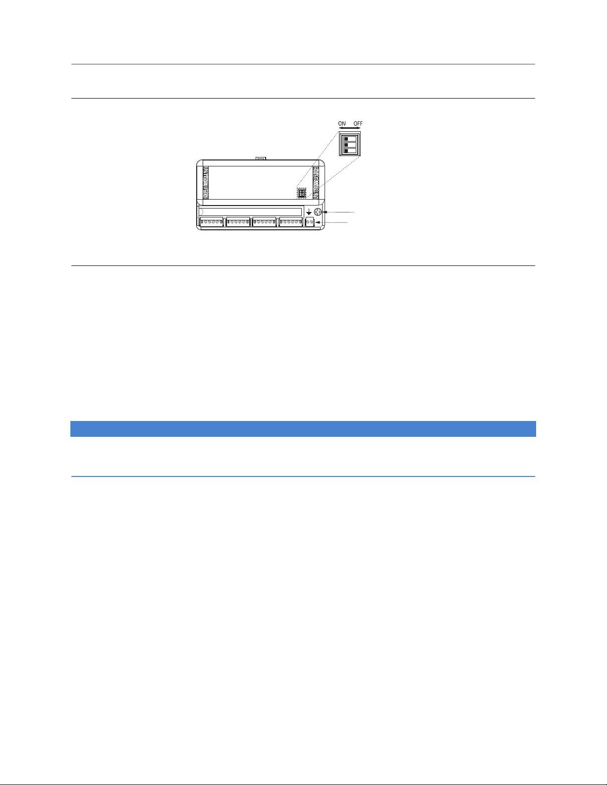
2.4 Switches
Figure 2-13: Switch location on the transmitter
Security
After configuring the transmitter, the data can be protected from unwarranted changes. Each transmitter is
equipped with a security switch that can be positioned ON to prevent the accidental or deliberate change of
configuration data. This switch is located on the front side of the electronics module and is labeled SECURITY.
For the switch location on the transmitter label, see Figure 2-13.
Simulate enable
The switch labeled SIMULATE ENABLE is used in conjunction with the Analog Input (AI) and Multiple Analog
Input (MAI) function blocks. This switch is used to simulate temperature measurement.
Not used
The switch is not functional.
2.5 Tagging
Commissioning tag
The Rosemount 848T has been supplied with a removable commissioning tag that contains both the Device
ID (the unique code that identifies a particular device in the absence of a device tag) and a space to record the
device tag (the operational identification for the device as defined by the Piping and Instrumentation Diagram
[P&ID]).
When commissioning more than one device on a fieldbus segment, it can be difficult to identify which device
is at a particular location. The removable tag, provided with the transmitter, can aid in this process by linking
the Device ID to its physical location. The installer should note the physical location of the transmitter on both
the upper and lower location of the commissioning tag. The bottom portion should be torn off for each
device on the segment and used for commissioning the segment in the control system.
Emerson.com/Rosemount 23

A
B
Installation
Reference Manual
January 2022 00809-0100-4697
Figure 2-14: Commissioning tag
A. Device ID
B. Device tag to denote physical location
Transmitter tag
Hardware
Software • The transmitter can store up to 32 characters.
• Tagged in accordance with customer requirements
• Permanently attached to the transmitter
• If no characters are specified, the first 30 characters of
the hardware tag will be used.
Sensor tag
Hardware
Software • If sensor tagging is requested, the Transducer Block
• A plastic tag is provided to record identification of eight
sensors.
• This information can be printed at the factory upon
request.
• In the field, the tag can be removed, printed onto, and
reattached to the transmitter.
SERIAL_NUMBER parameters will be set at the factory.
• The SERIAL_NUMBER parameters can be updated in the
field.
2.6 Installation
2.6.1 Using cable glands
Procedure
1. Remove the junction box cover by unscrewing the cover screws.
24 Emerson.com/Rosemount

%
+,-.
&'()*$
Reference Manual Installation
00809-0100-4697 January 2022
2. Run the sensor and power/signal wires through the appropriate cable glands (see Figure 2-15).
3. Install the sensor wires into the correct screw terminals (follow the label on the electronics module).
4. Install the power/signal wires onto the correct screw terminals. Power is polarity insensitive, allowing
the user to connect positive (+) or negative (–) to either fieldbus wiring terminal labeled “Bus”.
5. Replace the enclosure cover and securely tighten all cover screws.
Figure 2-15: Installing the transmitter with cable glands
A. Enclosure cover screws (2)
B. Cable glands (9)
C. Sensor 1
D. Sensor 3
E. Sensor 5
F. Sensor 7
G. Power/signal
H. Sensor 2
I. Sensor 4
J. Sensor 6
K. Sensor 8
Emerson.com/Rosemount 25

Installation Reference Manual
January 2022 00809-0100-4697
26 Emerson.com/Rosemount

Reference Manual Configuration
00809-0100-4697 January 2022
3 Configuration
3.1 Standard configuration
Each FOUNDATION Fieldbus configuration tool or host system has a different way of displaying and performing
configurations. Some will use Device Descriptions (DDs) and DD Methods to make configuration and
displaying of data consistent across host platforms.
Unless otherwise specified, the transmitter will be shipped with the following configuration (default):
Table 3-1: Standard configuration settings
(1)
(1)
(1)
(1)
(1)
Type J Thermocouple
5 seconds
°C
Linear with Temperature
60 Hz
Sensor Type
Damping
Measurement Units
Output
Line Voltage Filter
Temperature Specific Blocks • Transducer Block (1)
FOUNDATION Fieldbus Function Blocks • Analog Input (8)
• Multiple Analog Input (2)
• Input Selector (4)
(1) For all eight sensors
Refer to the systems documentation to perform configuration changes using a FOUNDATION Fieldbus host or
configuration tool.
Note
To make configuration changes, ensure that the block is Out of Service (OOS) by setting the
MODE_BLK.TARGET to OOS, or set the SENSOR_MODE to Configuration.
3.2 Transmitter configuration
The transmitter is available with the standard configuration setting. The configuration settings and block
configuration may be changed in the field with the Emerson Process Management Systems DeltaV™, with
AMS™ inside, or other FOUNDATION Fieldbus host or configuration tool.
3.3 Custom configuration
Custom configurations are specified when ordering.
Emerson.com/Rosemount 27

Configuration Reference Manual
January 2022 00809-0100-4697
3.4 Configure methods
For FOUNDATION Fieldbus hosts or configuration tools that support device description (DD) methods, there are
two configuration methods available in the transducer block. These methods are included with the DD
software.
• Sensor Configuration
• Sensor Input Trim (user input trim)
See the host system documentation for information on running DD methods from the host system. If the
FOUNDATION Fieldbus host or configuration tool does not support DD methods, for information on how to
modify sensor configuration parameters, refer to Configure blocks.
3.5 Configure alarms
Use the following steps to configure the alarms, which are located in the Resource Function Block:
Procedure
1. Set the resource block to OOS.
2. Set WRITE_PRI to the appropriate alarm level (WRITE_PRI has a selectable range of priorities from 0 to
15, see Table 3-4. Set the other block alarm parameters at this time.
3. Set CONFIRM_TIME to the time, in 1/32 of a millisecond, that the device will wait for confirmation of
receiving a report before trying again (the device does not retry if CONFIRM_TIME is 0).
4. Set LIM_NOTIFY to a value between zero and MAX_NOTIFY. LIM_NOTIFY is the maximum number of
alert reports allowed before the operator needs to acknowledge an alarm condition.
5. Enable the reports bit in FEATURES_SEL. (When multi-bit alerts is enabled, every active alarm is visible
for any of the eight sensors, generated by a Plantweb™ and field diagnostics alert. This is different than
only viewing the highest priority alarm.)
6. Set the resource block to AUTO.
For modifying alarms on individual function blocks (AI or ISEL blocks), refer to Function blocks.
3.6 Configure damping
Use the following steps to configure the damping, which is located in the transducer function block:
Procedure
1. Set Sensor Mode to Out of Service.
2. Change DAMPING to the desired filter rate (0.0 to 32.0 seconds).
3. Set Sensor Mode to In Service.
3.7 Configure the differential sensors
Use the following steps to configure the differential sensors:
28 Emerson.com/Rosemount

Reference Manual Configuration
00809-0100-4697 January 2022
Procedure
1. Set Dual Sensor Mode to Out of Service.
2. Set Input A and Input B to the sensor values that are to be used in the differential equation diff = A–B.
Note
Unit types must be the same.
3. Set the DUAL_SENSOR_CALC to either Not Used, Absolute, or INPUT A minus INPUT B.
4. Set Dual Sensor Mode to In Service.
3.8 Configure measurement validation
Use the following steps to configure measurement validation:
Procedure
1. Set mode to Disabled for specific sensor.
2. Select sample rate. 1-10 sec/sample is available. 1 second/sample is preferred for sensor degradation.
The higher the number of seconds between samples, the more emphasis put on process variation.
3. Select Deviation Limit from 0 to 10 units. If deviation limit is exceeded, a status event will be triggered.
4. Select Increasing Limit. Sets the limit for increasing rate of change. If limit is exceeded, a status event
will be triggered.
5. Select Decreasing Limit. Sets the limit for decreasing rate of change. If limit is exceeded, a status event
will be triggered.
Note
The decreasing limit selected is required to be a negative value.
6. Set the Deadband from 0 to 90%. This threshold is used to clear the PV status.
7. Set Status Priority. This determines what happens when the specific limit has been exceeded.
No Alert Ignores limit settings
Advisory Sets a Advisory Plant Web Alert, but does not do
anything with PV status
Warning Sets a Maintenance Plant Web Alert and sets PV status
to uncertain
Failure Sets a Failure Plant Web Alert and sets PV status to Bad
8. Set mode to Enabled for specific sensor.
3.9 Common configurations for high density applications
For the application to work properly, configure the links between the function blocks and schedule the order
of their execution. The Graphical User Interface (GUI) provided by the FOUNDATION Fieldbus host or
configuration tool will allow easy configuration.
Emerson.com/Rosemount 29

Configuration Reference Manual
January 2022 00809-0100-4697
The measurement strategies shown in this section represent some of the common types of configurations
available in the Rosemount 848T. Although the appearance of the GUI screens will vary from host to host, the
configuration logic is the same.
NOTICE
Ensure the host system or configuration tool is properly configured before downloading the transmitter
configuration. If configured improperly, the FOUNDATION Fieldbus host or configuration tool could overwrite
the default transmitter configuration.
3.9.1 Configure a typical profiling application
Procedure
1. Place the Multiple Analog Input (MAI) function block in OOS mode (set MODE_BLK.TARGET to OOS).
2. Set CHANNEL = channels 1 to 8. Although the CHANNEL_X parameters remain writable, CHANNEL_X
can only be set = X when CHANNEL = 1.
3. Set L_TYPE to direct or indirect.
4. Set XD_SCALE (transducer measurement scaling) to the appropriate upper and lower range values, the
appropriate sensor units, and display decimal point.
5. Set OUT_SCALE (MAI output scaling) to the appropriate upper and lower range values, the appropriate
sensor units, and display decimal point.
6. Place the MAI Function Block in auto mode.
7. Verify that the function blocks are scheduled.
Example
The following illustration describes a distillation column temperature profile where all channels have the
same sensor units (°C, °F, etc.).
3.9.2 Monitor an application with a single selection
Procedure
1. Link the MAI outputs to the ISEL inputs.
2. Place the Multiple Analog Input (MAI) function block in OOS mode (set MODE_BLK.TARGET to OOS).
3. Set CHANNEL = channels 1 to 8. Although the CHANNEL_X parameters remain writable, CHANNEL_X
can only be set = X when CHANNEL = 1.
4. Set L_TYPE to direct or indirect.
30 Emerson.com/Rosemount
Loading...