

Manual: Rosemount 5900 Instruction for Installation, Configuration, and Operation of Proof Test Function with Reference Reflector
Table of contents
 Loading...
Rosemount Manual: Rosemount 5900 Instruction for Installation, Configuration, and Operation of Proof Test Function with Reference Reflector Manuals & Guides

Manual Supplement
00809-0200-5900, Rev AC
November 2019
Rosemount™ 5900
Instruction for Installation, Configuration, and Operation of
Proof Test Function with Reference Reflector


Manual Supplement
00809-0200-5900, Rev AC
Contents
1Section 1: Introduction
2Section 2: Installation
Contents
November 2019
1.1 Section overview . . . . . . . . . . . . . . . . . . . . . . . . . . . . . . . . . . . . . . . . . . . . . . . . . . . . . . .2
1.2 Service support. . . . . . . . . . . . . . . . . . . . . . . . . . . . . . . . . . . . . . . . . . . . . . . . . . . . . . . . .2
1.3 Installation procedure . . . . . . . . . . . . . . . . . . . . . . . . . . . . . . . . . . . . . . . . . . . . . . . . . . .3
2.1 Overview . . . . . . . . . . . . . . . . . . . . . . . . . . . . . . . . . . . . . . . . . . . . . . . . . . . . . . . . . . . . . .5
2.2 Safety messages. . . . . . . . . . . . . . . . . . . . . . . . . . . . . . . . . . . . . . . . . . . . . . . . . . . . . . . .5
2.3 Installation considerations . . . . . . . . . . . . . . . . . . . . . . . . . . . . . . . . . . . . . . . . . . . . . . .6
2.4 Installing the Reference Reflector for Parabolic Antenna . . . . . . . . . . . . . . . . . . . . .7
2.4.1 Reference Reflector Kit . . . . . . . . . . . . . . . . . . . . . . . . . . . . . . . . . . . . . . . . . . . . 7
2.4.2 Tank Geometry - Parabolic Antenna . . . . . . . . . . . . . . . . . . . . . . . . . . . . . . . . . 9
2.4.3 Installing the Reference Reflector . . . . . . . . . . . . . . . . . . . . . . . . . . . . . . . . . .11
2.5 Installing the Reference Reflector for Array Antenna . . . . . . . . . . . . . . . . . . . . . . .18
2.5.1 Reference Reflector Kit . . . . . . . . . . . . . . . . . . . . . . . . . . . . . . . . . . . . . . . . . . .18
2.5.2 Tank Geometry - Array Antenna. . . . . . . . . . . . . . . . . . . . . . . . . . . . . . . . . . . .20
2.5.3 Installing the Reference Reflector . . . . . . . . . . . . . . . . . . . . . . . . . . . . . . . . . .23
3Section 3: Configuration of Reference Reflector
3.1 Overview . . . . . . . . . . . . . . . . . . . . . . . . . . . . . . . . . . . . . . . . . . . . . . . . . . . . . . . . . . . . .29
3.2 Safety messages. . . . . . . . . . . . . . . . . . . . . . . . . . . . . . . . . . . . . . . . . . . . . . . . . . . . . . .29
3.3 Configuration using TankMaster WinSetup . . . . . . . . . . . . . . . . . . . . . . . . . . . . . . .30
3.3.1 Introduction. . . . . . . . . . . . . . . . . . . . . . . . . . . . . . . . . . . . . . . . . . . . . . . . . . . . .30
3.3.2 Considerations . . . . . . . . . . . . . . . . . . . . . . . . . . . . . . . . . . . . . . . . . . . . . . . . . .30
3.3.3 Configuration procedure. . . . . . . . . . . . . . . . . . . . . . . . . . . . . . . . . . . . . . . . . .31
Contents
i

Contents
November 2019
Manual Supplement
00809-0200-5900, Rev AC
4Section 4: Operation
4.1 Overview . . . . . . . . . . . . . . . . . . . . . . . . . . . . . . . . . . . . . . . . . . . . . . . . . . . . . . . . . . . . .39
4.2 Safety messages. . . . . . . . . . . . . . . . . . . . . . . . . . . . . . . . . . . . . . . . . . . . . . . . . . . . . . .39
4.3 Proof Test operation . . . . . . . . . . . . . . . . . . . . . . . . . . . . . . . . . . . . . . . . . . . . . . . . . . .40
4.3.1 Proof Test status . . . . . . . . . . . . . . . . . . . . . . . . . . . . . . . . . . . . . . . . . . . . . . . . .43
4.4 Scheduling. . . . . . . . . . . . . . . . . . . . . . . . . . . . . . . . . . . . . . . . . . . . . . . . . . . . . . . . . . . .44
4.4.1 Pop-up message . . . . . . . . . . . . . . . . . . . . . . . . . . . . . . . . . . . . . . . . . . . . . . . . .45
4.5 History . . . . . . . . . . . . . . . . . . . . . . . . . . . . . . . . . . . . . . . . . . . . . . . . . . . . . . . . . . . . . . .46
4.6 Reports. . . . . . . . . . . . . . . . . . . . . . . . . . . . . . . . . . . . . . . . . . . . . . . . . . . . . . . . . . . . . . .47
4.6.1 Viewing a report . . . . . . . . . . . . . . . . . . . . . . . . . . . . . . . . . . . . . . . . . . . . . . . . .48
4.7 Removing a Reference Reflector . . . . . . . . . . . . . . . . . . . . . . . . . . . . . . . . . . . . . . . . .50
5Section 5: Service and Troubleshooting
5.1 Safety messages. . . . . . . . . . . . . . . . . . . . . . . . . . . . . . . . . . . . . . . . . . . . . . . . . . . . . . .51
5.2 Troubleshooting. . . . . . . . . . . . . . . . . . . . . . . . . . . . . . . . . . . . . . . . . . . . . . . . . . . . . . .52
5.3 Tank spectrum . . . . . . . . . . . . . . . . . . . . . . . . . . . . . . . . . . . . . . . . . . . . . . . . . . . . . . . .53
ii
Contents

Manual Supplement
Reference Reflector for
Proof Testing
Reference Reflector for
Proof Testing
ROSEMOUNT 5900 WITH PARABOLIC ANTENNA ROSEMOUNT 5900 WITH ARRAY ANTENNA
00809-0200-5900, Rev AC
Section 1: Introduction
November 2019
Section 1 Introduction
The Rosemount 5900 Radar Level Gauge is designed with functionality that lets you proof test
high alarms and verify correct product surface measurement. The Rosemount 5900 allows you
to combine continuous product level monitoring with proof testing at regular intervals. It is
based on a dedicated Reference Reflector that introduces a radar echo at a predefined position
in the tank.
Figure 1-1. The Rosemount 5900 can be equipped with an optional Reference Reflector that allows proof
testing the gauge on a regular basis.
Introduction
1

Section 1: Introduction
November 2019
1.1 Section overview
This document is a supplement to the Rosemount 5900S Reference Manual (Document No.
00809-0100-5900).
The sections in this reference manual supplement provide information on installing, operating,
and maintaining the Rosemount 5900 Proof Test System. The sections are organized as follows:
Section 1: Introduction gives a brief introduction to the Rosemount 5900 Proof Test function
and the recommended installation procedure.
Section 2: Installation provides instructions on how to install the Reference Reflector on the
Rosemount 5900 with Parabolic Antenna and Array Antenna.
Section 3: Configuration contains instructions on how to calibrate and configure the
Rosemount 5900 Proof Test function.
Section 4: Operation provides instructions for how to use the proof test function.
Section 5: Service and Troubleshooting provides troubleshooting techniques for the most
common operating problems.
Manual Supplement
00809-0200-5900, Rev AC
1.2 Service support
For service support contact the nearest Emerson Process Management/Rosemount Tank Gauging
representative. Contact information can be found on the web site www.Emerson.com.
2
Introduction

Manual Supplement
Review installation considerations.
See “Installation considerations” on page 6.
Mount the Proof Test Reference Reflector.
See “Installing the Reference Reflector for Parabolic Antenna” on
page 7 and “Installing the Reference Reflector for Array Antenna”
on page 18.
Wire the Rosemount 5900
(1)
gauge.
Ensure covers and cable gland/conduit connections are tight.
Configure the Rosemount 5900 for proof testing.
See Section 3: Configuration of Reference Reflector
Verify operation.
(1) See the Rosemount 5900S Reference manual (Document No. 00809-0100-5900 or the
Rosemount 5900C Reference manual (Document No. 00809-0100-5901)
00809-0200-5900, Rev AC
1.3 Installation procedure
Follow these steps for a proper installation of the Reference Reflector for Proof Testing a
Rosemount 5900 Radar Level Gauge.
Section 1: Introduction
November 2019
Introduction
3

Section 1: Introduction
November 2019
Manual Supplement
00809-0200-5900, Rev AC
4
Introduction

Manual Supplement
00809-0200-5900, Rev AC
Section 2 Installation
Overview . . . . . . . . . . . . . . . . . . . . . . . . . . . . . . . . . . . . . . . . . . . . . . . . . . . . . . . . . . . . . . . . . . page 5
Safety messages . . . . . . . . . . . . . . . . . . . . . . . . . . . . . . . . . . . . . . . . . . . . . . . . . . . . . . . . . . . . page 5
Installation considerations . . . . . . . . . . . . . . . . . . . . . . . . . . . . . . . . . . . . . . . . . . . . . . . . . . . page 6
Installing the Reference Reflector for Parabolic Antenna . . . . . . . . . . . . . . . . . . . . . . . . . page 7
Installing the Reference Reflector for Array Antenna . . . . . . . . . . . . . . . . . . . . . . . . . . . . . page 18
2.1 Overview
The information in this section covers installation of Reference Reflector for proof testing the
Rosemount 5900 Radar Level Gauge.
2.2 Safety messages
Section 2: Installation
November 2019
Procedures and instructions in this section may require special precautions to ensure the safety
of the personnel performing the operation. Information that raises potential safety issues is
indicated by a warning symbol ( ). Refer to the following safety messages before performing
an operation preceded by this symbol.
Failure to follow safe installation and servicing guidelines could result in death or
serious injury:
Make sure only qualified personnel perform the installation.
Use the equipment only as specified in this manual. Failure to do so may impair the
protection provided by the equipment.
Do not perform any service other than those contained in this manual unless you are
qualified.
High voltage that may be present on leads could cause electrical shock:
Avoid contact with leads and terminals.
Make sure the main power to the 2460 System Hub is off and the lines to any other external
power source are disconnected or not powered while wiring the 2460.
Electrical shock could cause death or serious injury:
Use extreme caution when making contact with the leads and terminals.
Installation
Handle the wire and assembly with care to avoid permanent bends.
5

Section 2: Installation
November 2019
2.3 Installation considerations
Before you start installing the Reference Reflector, ensure that the following items are
considered in order to fulfill the installation requirements for the Reference Reflector at the
desired position:
Maximum product level in the tank
High Alarm position
Minimum / maximum distance between Gauge Reference Point and Reference
Reflector
See “Tank Geometry - Parabolic Antenna” on page 9 and “Tank Geometry - Array Antenna” on
page 20 for further information on tank geometry and position of the Reference Reflector.
Note
The Reference Reflector for Array Antenna may need to be removed to allow product sampling
through the Still-pipe.
Manual Supplement
00809-0200-5900, Rev AC
6
Installation

Manual Supplement
Nut M8
Spring washer
Washer
Nut M8
M8 terminal
Wire Ø 4 mm
Length 5 m
Wire Ø 4 mm
Length 5 m
M8 terminal
Nut M12
Spring washer
Weight
M6 screw (x2)
Allen key size 3
00809-0200-5900, Rev AC
Section 2: Installation
November 2019
2.4 Installing the Reference Reflector for Parabolic Antenna
The Reference Reflector is installed under the antenna. It is attached to a wire fixed to the
Parabolic Antenna. The Reference Reflector introduces a radar echo that is used for proof testing
the Rosemount 5900 Radar Level Gauge. Proof testing can be performed without the need to
open the tank.
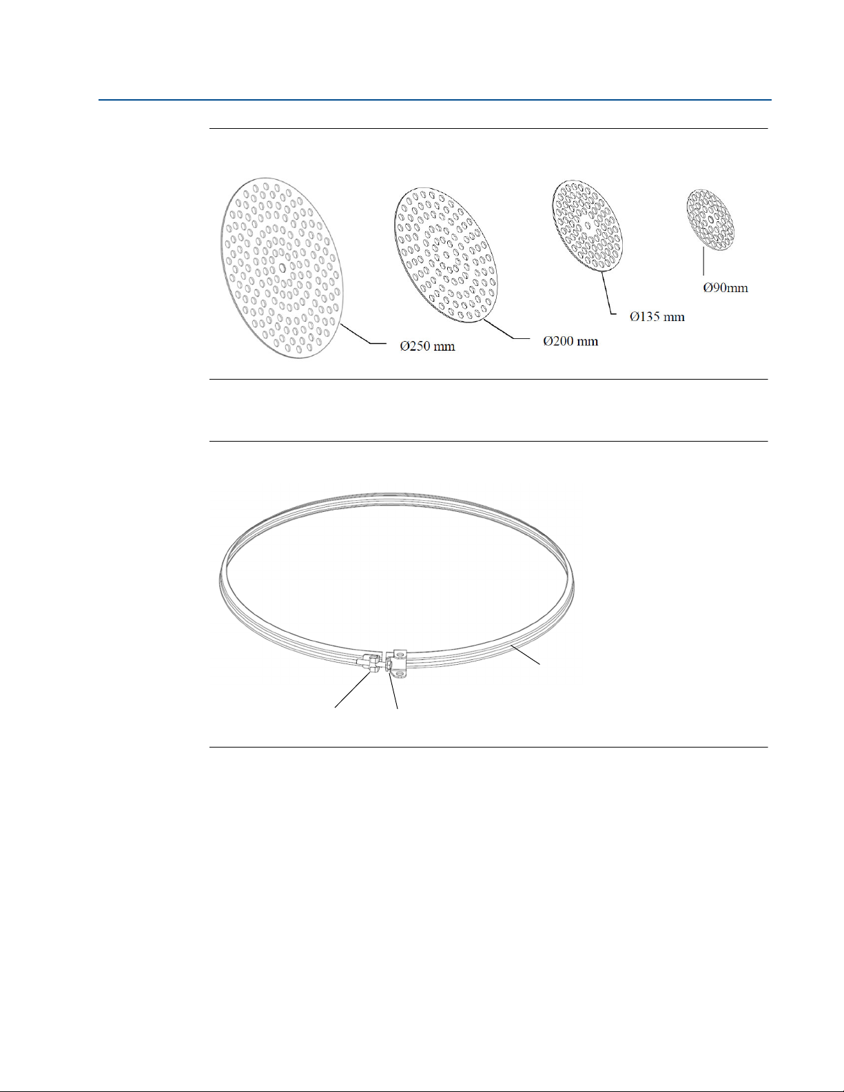
2.4.1 Reference Reflector Kit
The Reference Reflector is delivered with all parts needed for proper installation on a Rosemount
5900 with Parabolic Antenna. The Reference Reflector kit includes the following parts:
Wire assembly
Weight assembly
Reference Reflector
Ring Clamping assembly
Figure 2-1. Wire and Weight Assembly
Installation
7
Section 2: Installation
M6 cylinder nut M6 screw
Clamping ring
November 2019
Figure 2-2. Reference Reflector
Figure 2-3. Clamping Ring
Manual Supplement
00809-0200-5900, Rev AC
8
Installation
Manual Supplement
Wire
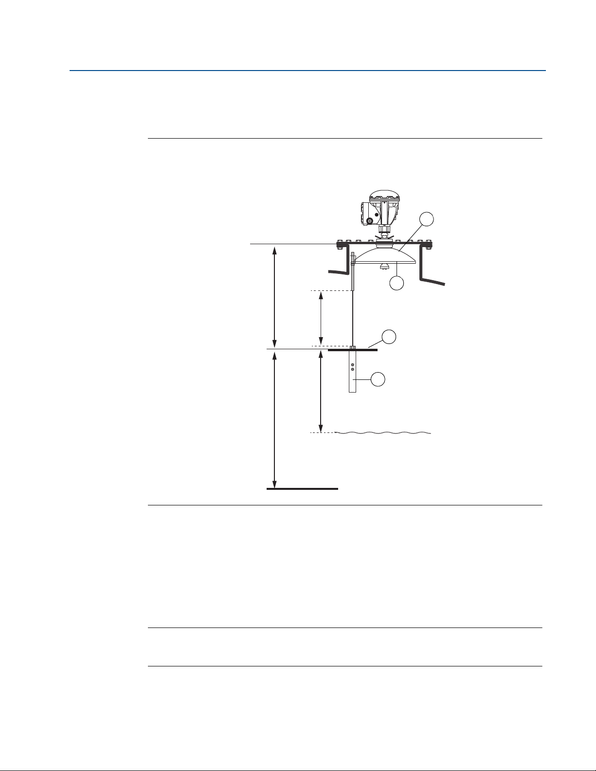
Distance
Reference Reflector (RR) Distance
Minimum: 600 mm
Maximum: 5000 mm
Reference Reflector (RR) Position
Minimum 500 mm
3
4
1
2
Zero Level
Max. product level
Gauge Reference Point
00809-0200-5900, Rev AC
2.4.2 Tank Geometry - Parabolic Antenna
Figure 2-4. Tank geometry for Rosemount 5900 with Parabolic Antenna and Proof Test
Reference Reflector.
Section 2: Installation
November 2019
1. Reference Reflector (RR). Maximum inclination 2.5°.
2. Weight
3. Clamping ring
4. Parabolic antenna
Note
See “Safety Instrumented System (SIS)” on page 10 for installation requirements in Safety
Instrumented Systems (SIS).
Installation
9
Section 2: Installation
4
21
Max. product level
Gauge Reference Point
3
5
November 2019
Manual Supplement
00809-0200-5900, Rev AC
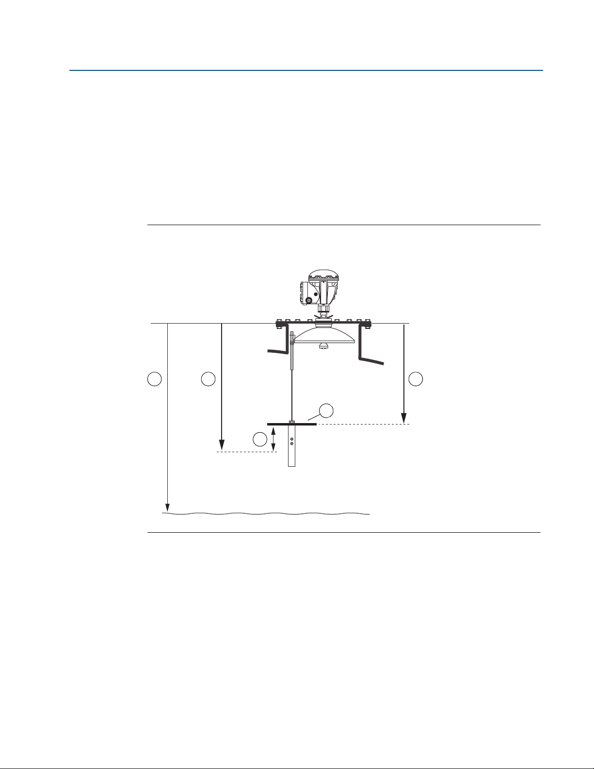
Safety Instrumented System
(1)
(SIS)
1. Decide position of SIL High Alarm.
2. Find a position for the Reference Reflector (RR) that fulfills the following requirements:
a. Minimum 500 mm above SIL High Alarm Limit.
b. Distance RR - Gauge Reference Point: 600 to 5000 mm.
c. Minimum 500 mm to maximum product level.
Figure 2-5. Tank geometry for Rosemount 5900 with Parabolic Antenna and Proof Test
Reference Reflector in Safety Instrumented System (SIS).
1. SIL Surface Distance
2. SIL High Alarm Limit
3. Distance RR - Gauge Reference Point: 600 to 5000 mm
4. Minimum distance RR - SIL High Alarm = 500 mm
5. Reference Reflector (RR)
(1) See the Rosemount 5900 and 2410 Safety Manual (Document No. 00809-0200-5100) for information on how to install and con-
figure the Rosemount 5900 Radar Level Gauge and 2410 Tank Hub in a Safety Instrumented System.
10
Installation

Manual Supplement
1
4
1. Reference Reflector (RR)
2. M12 Nut. Torque=18 Nm
3. Spring washer
4. Weight
3
2
00809-0200-5900, Rev AC
2.4.3 Installing the Reference Reflector
The length of the wire that holds the Reference Reflector needs to be calculated before the
Reference Reflector can be installed in the tank. The wire must be long enough to allow the
Reflector to be properly positioned in the tank including the weight that is attached under the
Reflector.
Handle the wire and assembly with care to avoid permanent bends.
1. Specify the position of the Reference Reflector (RR) and calculate the Reference
Reflector Distance (see Figure 2-4 on page 9).
2. Choose the appropriate reflector size. As a result of the radar beam geometry, a smaller
reflector can be used further away from the radar gauge. There are four different
Reference Reflectors to choose from depending on the Reference Reflector Distance as
shown in Table 2-1.
Section 2: Installation
November 2019
Table 2-1. Reference Reflector Size for Various Distances
Reference Reflector Distance (mm) Diameter (mm)
600 RR Distance < 2000 250
2000 RR Distance < 3000 200
3000 RR Distance < 4000 135
4000 RR Distance < 5000 90
3. Mount the appropriate Reference Reflector on the weight.
4. Tighten the M12 nut to a torque value of 18 Nm.
Installation
11

Section 2: Installation
1
2
Wire Distance
1. Reference Reflector (RR)
2. Weight
M6 x 2
Allen key size 3
Torque=2.5 Nm
Cut the wire 0 - 150 mm
under the weight
November 2019
5. Calculate the required Wire Distance. See “Wire Distance calculation” on page 15.
6. Feed the wire through the weight and the Reference Reflector (RR).
Manual Supplement
00809-0200-5900, Rev AC
12
7. Position the weight so the calculated Wire Distance is obtained.
8. Tighten the two screws (size M6) to a torque value of 2.5 Nm.
9. Cut the wire. You may leave 0 to 150 mm of the wire below the weight.
Installation

Manual Supplement
Parabolic antenna
A - A
M6 Screw
Torque = 2.3
Clamping ring
A
A
Clamping ring
Parabolic antenna
Nut M8
Torque = 8 Nm
Tank center
Nut M8
Spring washer
Washer
Wire
M8 terminal
Clamping ring
Antenna
00809-0200-5900, Rev AC
10. Mount the clamping ring (see Figure 2-3 on page 8) on the Parabolic Antenna. Ensure
Section 2: Installation
November 2019
that the Reference Reflector is directed towards the center of the tank as illustrated in
Figure 2-4 on page 9.
11. Mount the M8 terminal (which holds the weight and Reference Reflector) on the
clamping ring.
12. Tighten the M8 nut to the specified torque of 8 Nm.
Installation
13

Section 2: Installation
Reference Reflector (RR)
Tank center
Parabolic antenna
Tank wall
November 2019
13. Ensure that:
the Reference Reflector is correctly aligned towards the center of the tank
inclination of Reference Reflector is less than 2.5°.
Figure 2-6. Align the Reference Reflector
Manual Supplement
00809-0200-5900, Rev AC
14
Installation

Manual Supplement
1
2
Wire Distance
1. Reference Reflector (RR)
2. Weight
00809-0200-5900, Rev AC
Wire Distance calculation
There are two different connections available for the Parabolic Antenna; the Welded and the
Clamped versions. Since the vertical position of the flange will differ slightly for these two
connections, you will have to use different formulas for calculating the proper Wire Distance in
order to obtain the correct position (Reference Reflector Distance) of the Reference Reflector.
Figure 2-7. Wire Distance
Section 2: Installation
November 2019
Installation
15
Loading...