


Reference Manual
00809-0100-4088, Rev DB
April 2018
Rosemount™ 4088 MultiVariable™ Transmitter

Reference Manual
00809-0100-4088, Rev DB
Section Title
April 2018
ii

Reference Manual
00809-0100-4088, Rev DB
Contents
1Section 1: Introduction
2Section 2: Configuration
Contents
April 2018
1.1 Using this manual . . . . . . . . . . . . . . . . . . . . . . . . . . . . . . . . . . . . . . . . . . . . . . . . . . . . . . . . . . . . . . . . . 1
1.1.1 Models covered. . . . . . . . . . . . . . . . . . . . . . . . . . . . . . . . . . . . . . . . . . . . . . . . . . . . . . . . . . . . . . 1
1.2 Product recycling/disposal. . . . . . . . . . . . . . . . . . . . . . . . . . . . . . . . . . . . . . . . . . . . . . . . . . . . . . . . . . 1
2.1 Safety messages. . . . . . . . . . . . . . . . . . . . . . . . . . . . . . . . . . . . . . . . . . . . . . . . . . . . . . . . . . . . . . . . . . . 3
2.2 Software installation and initial setup . . . . . . . . . . . . . . . . . . . . . . . . . . . . . . . . . . . . . . . . . . . . . . . . 4
2.2.1 System requirements . . . . . . . . . . . . . . . . . . . . . . . . . . . . . . . . . . . . . . . . . . . . . . . . . . . . . . . . 4
2.2.2 RTIS part numbers . . . . . . . . . . . . . . . . . . . . . . . . . . . . . . . . . . . . . . . . . . . . . . . . . . . . . . . . . . . 4
2.2.3 Installing the RTIS . . . . . . . . . . . . . . . . . . . . . . . . . . . . . . . . . . . . . . . . . . . . . . . . . . . . . . . . . . . . 4
2.2.4 Getting started with RTIS . . . . . . . . . . . . . . . . . . . . . . . . . . . . . . . . . . . . . . . . . . . . . . . . . . . . . 5
2.2.5 Connecting to a personal computer . . . . . . . . . . . . . . . . . . . . . . . . . . . . . . . . . . . . . . . . . . . . 7
2.3 Launching the configuration process. . . . . . . . . . . . . . . . . . . . . . . . . . . . . . . . . . . . . . . . . . . . . . . . . 8
2.4 Basic device configuration . . . . . . . . . . . . . . . . . . . . . . . . . . . . . . . . . . . . . . . . . . . . . . . . . . . . . . . . . 10
2.4.1 Units of measure and damping . . . . . . . . . . . . . . . . . . . . . . . . . . . . . . . . . . . . . . . . . . . . . . . 10
2.4.2 Network . . . . . . . . . . . . . . . . . . . . . . . . . . . . . . . . . . . . . . . . . . . . . . . . . . . . . . . . . . . . . . . . . . . 11
2.5 Detailed device configuration . . . . . . . . . . . . . . . . . . . . . . . . . . . . . . . . . . . . . . . . . . . . . . . . . . . . . . 12
2.5.1 Display . . . . . . . . . . . . . . . . . . . . . . . . . . . . . . . . . . . . . . . . . . . . . . . . . . . . . . . . . . . . . . . . . . . . 12
2.5.2 Device information . . . . . . . . . . . . . . . . . . . . . . . . . . . . . . . . . . . . . . . . . . . . . . . . . . . . . . . . . 14
2.5.3 Overview variables . . . . . . . . . . . . . . . . . . . . . . . . . . . . . . . . . . . . . . . . . . . . . . . . . . . . . . . . . . 14
2.5.4 Alert setup . . . . . . . . . . . . . . . . . . . . . . . . . . . . . . . . . . . . . . . . . . . . . . . . . . . . . . . . . . . . . . . . . 15
2.6 Variable configuration . . . . . . . . . . . . . . . . . . . . . . . . . . . . . . . . . . . . . . . . . . . . . . . . . . . . . . . . . . . . 16
2.6.1 Differential pressure . . . . . . . . . . . . . . . . . . . . . . . . . . . . . . . . . . . . . . . . . . . . . . . . . . . . . . . . 16
2.6.2 Static pressure. . . . . . . . . . . . . . . . . . . . . . . . . . . . . . . . . . . . . . . . . . . . . . . . . . . . . . . . . . . . . . 16
2.6.3 Process temperature . . . . . . . . . . . . . . . . . . . . . . . . . . . . . . . . . . . . . . . . . . . . . . . . . . . . . . . . 17
2.6.4 Module temperature . . . . . . . . . . . . . . . . . . . . . . . . . . . . . . . . . . . . . . . . . . . . . . . . . . . . . . . . 19
2.7 Menu trees and Field Communicator. . . . . . . . . . . . . . . . . . . . . . . . . . . . . . . . . . . . . . . . . . . . . . . . 20
2.7.1 Rosemount 4088A menu tree . . . . . . . . . . . . . . . . . . . . . . . . . . . . . . . . . . . . . . . . . . . . . . . . 21
2.7.2 Rosemount 4088B menu tree . . . . . . . . . . . . . . . . . . . . . . . . . . . . . . . . . . . . . . . . . . . . . . . . 27
2.7.3 Field Communicator . . . . . . . . . . . . . . . . . . . . . . . . . . . . . . . . . . . . . . . . . . . . . . . . . . . . . . . . 33
2.8 Rosemount 4088A configuration with legacy tool . . . . . . . . . . . . . . . . . . . . . . . . . . . . . . . . . . . . 34
Contents
iii

Contents
April 2018
Reference Manual
00809-0100-4088, Rev DB
3Section 3: Installation
3.1 Overview . . . . . . . . . . . . . . . . . . . . . . . . . . . . . . . . . . . . . . . . . . . . . . . . . . . . . . . . . . . . . . . . . . . . . . . . 35
3.2 Safety messages. . . . . . . . . . . . . . . . . . . . . . . . . . . . . . . . . . . . . . . . . . . . . . . . . . . . . . . . . . . . . . . . . . 35
3.3 Considerations . . . . . . . . . . . . . . . . . . . . . . . . . . . . . . . . . . . . . . . . . . . . . . . . . . . . . . . . . . . . . . . . . . . 36
3.3.1 General . . . . . . . . . . . . . . . . . . . . . . . . . . . . . . . . . . . . . . . . . . . . . . . . . . . . . . . . . . . . . . . . . . . . 36
3.3.2 Mechanical . . . . . . . . . . . . . . . . . . . . . . . . . . . . . . . . . . . . . . . . . . . . . . . . . . . . . . . . . . . . . . . . 37
3.3.3 Environmental . . . . . . . . . . . . . . . . . . . . . . . . . . . . . . . . . . . . . . . . . . . . . . . . . . . . . . . . . . . . . 37
3.4 Steps required for quick installation. . . . . . . . . . . . . . . . . . . . . . . . . . . . . . . . . . . . . . . . . . . . . . . . . 37
3.4.1 Mount the transmitter. . . . . . . . . . . . . . . . . . . . . . . . . . . . . . . . . . . . . . . . . . . . . . . . . . . . . . . 38
3.4.2 Consider housing rotation . . . . . . . . . . . . . . . . . . . . . . . . . . . . . . . . . . . . . . . . . . . . . . . . . . . 42
3.4.3 Set the switches . . . . . . . . . . . . . . . . . . . . . . . . . . . . . . . . . . . . . . . . . . . . . . . . . . . . . . . . . . . . 43
3.4.4 Wiring and power up . . . . . . . . . . . . . . . . . . . . . . . . . . . . . . . . . . . . . . . . . . . . . . . . . . . . . . . . 44
3.4.5 Verify device configuration. . . . . . . . . . . . . . . . . . . . . . . . . . . . . . . . . . . . . . . . . . . . . . . . . . . 48
3.4.6 Trim the transmitter . . . . . . . . . . . . . . . . . . . . . . . . . . . . . . . . . . . . . . . . . . . . . . . . . . . . . . . . 48
3.5 Rosemount 305, 306, and 304 Manifolds . . . . . . . . . . . . . . . . . . . . . . . . . . . . . . . . . . . . . . . . . . . . 49
3.5.1 Rosemount 305 Integral Manifold installation procedure . . . . . . . . . . . . . . . . . . . . . . . . 49
3.5.2 Rosemount 306 In-line Manifold installation procedure. . . . . . . . . . . . . . . . . . . . . . . . . . 50
3.5.3 Rosemount 304 Conventional Manifold installation procedure . . . . . . . . . . . . . . . . . . . 50
3.5.4 Rosemount 305 and 304 Manifold styles. . . . . . . . . . . . . . . . . . . . . . . . . . . . . . . . . . . . . . . 51
3.5.5 Manifold operation. . . . . . . . . . . . . . . . . . . . . . . . . . . . . . . . . . . . . . . . . . . . . . . . . . . . . . . . . . 52
4Section 4: Communication
4.1 Rosemount 4088A Modbus communications . . . . . . . . . . . . . . . . . . . . . . . . . . . . . . . . . . . . . . . . 57
4.1.1 Modbus communication overview . . . . . . . . . . . . . . . . . . . . . . . . . . . . . . . . . . . . . . . . . . . 57
4.1.2 Modbus data types. . . . . . . . . . . . . . . . . . . . . . . . . . . . . . . . . . . . . . . . . . . . . . . . . . . . . . . . . 58
4.1.3 Modbus function codes. . . . . . . . . . . . . . . . . . . . . . . . . . . . . . . . . . . . . . . . . . . . . . . . . . . . . 59
4.1.4 Registers for process variables. . . . . . . . . . . . . . . . . . . . . . . . . . . . . . . . . . . . . . . . . . . . . . . 59
4.1.5 Process variable integer scaling . . . . . . . . . . . . . . . . . . . . . . . . . . . . . . . . . . . . . . . . . . . . . . 60
4.1.6 Floating point formats. . . . . . . . . . . . . . . . . . . . . . . . . . . . . . . . . . . . . . . . . . . . . . . . . . . . . . 61
4.1.7 Communications . . . . . . . . . . . . . . . . . . . . . . . . . . . . . . . . . . . . . . . . . . . . . . . . . . . . . . . . . . 62
4.1.8 Implementing calibration . . . . . . . . . . . . . . . . . . . . . . . . . . . . . . . . . . . . . . . . . . . . . . . . . . . 62
4.1.9 Diagnostics . . . . . . . . . . . . . . . . . . . . . . . . . . . . . . . . . . . . . . . . . . . . . . . . . . . . . . . . . . . . . . . 63
4.1.10 Transmitter register maps . . . . . . . . . . . . . . . . . . . . . . . . . . . . . . . . . . . . . . . . . . . . . . . . . . 65
4.2 Rosemount 4088B ROC communications. . . . . . . . . . . . . . . . . . . . . . . . . . . . . . . . . . . . . . . . . . . . 77
4.3 Rosemount 4088B BSAP communications . . . . . . . . . . . . . . . . . . . . . . . . . . . . . . . . . . . . . . . . . . . 78
4.3.1 Rosemount 4088B BSAP communications signals. . . . . . . . . . . . . . . . . . . . . . . . . . . . . . . 78
iv
Contents

Reference Manual
00809-0100-4088, Rev DB
5Section 5: Operation and Maintenance
6Section 6: Troubleshooting
Contents
April 2018
5.1 Calibration. . . . . . . . . . . . . . . . . . . . . . . . . . . . . . . . . . . . . . . . . . . . . . . . . . . . . . . . . . . . . . . . . . . . . . 105
5.1.1 Sensor trim overview . . . . . . . . . . . . . . . . . . . . . . . . . . . . . . . . . . . . . . . . . . . . . . . . . . . . . . .105
5.1.2 Differential pressure sensor calibration . . . . . . . . . . . . . . . . . . . . . . . . . . . . . . . . . . . . . . . 106
5.1.3 Static pressure sensor calibration . . . . . . . . . . . . . . . . . . . . . . . . . . . . . . . . . . . . . . . . . . . . 109
5.1.4 Process temperature sensor calibration. . . . . . . . . . . . . . . . . . . . . . . . . . . . . . . . . . . . . . . 109
5.1.5 Offset . . . . . . . . . . . . . . . . . . . . . . . . . . . . . . . . . . . . . . . . . . . . . . . . . . . . . . . . . . . . . . . . . . . . 110
5.1.6 Verification . . . . . . . . . . . . . . . . . . . . . . . . . . . . . . . . . . . . . . . . . . . . . . . . . . . . . . . . . . . . . . .111
5.1.7 Legacy calibration. . . . . . . . . . . . . . . . . . . . . . . . . . . . . . . . . . . . . . . . . . . . . . . . . . . . . . . . . . 111
5.2 Simulate device variables . . . . . . . . . . . . . . . . . . . . . . . . . . . . . . . . . . . . . . . . . . . . . . . . . . . . . . . . . 112
6.1 Overview . . . . . . . . . . . . . . . . . . . . . . . . . . . . . . . . . . . . . . . . . . . . . . . . . . . . . . . . . . . . . . . . . . . . . . . 113
6.2 Safety messages. . . . . . . . . . . . . . . . . . . . . . . . . . . . . . . . . . . . . . . . . . . . . . . . . . . . . . . . . . . . . . . . . 113
6.3 Communications troubleshooting . . . . . . . . . . . . . . . . . . . . . . . . . . . . . . . . . . . . . . . . . . . . . . . . . 114
6.4 Alarms and conditions . . . . . . . . . . . . . . . . . . . . . . . . . . . . . . . . . . . . . . . . . . . . . . . . . . . . . . . . . . . 115
6.5 Field upgrades and replacements. . . . . . . . . . . . . . . . . . . . . . . . . . . . . . . . . . . . . . . . . . . . . . . . . . 117
6.5.1 Disassembly considerations . . . . . . . . . . . . . . . . . . . . . . . . . . . . . . . . . . . . . . . . . . . . . . . . . 117
6.5.2 Housing assembly including electronics board. . . . . . . . . . . . . . . . . . . . . . . . . . . . . . . . . 117
6.5.3 Terminal block . . . . . . . . . . . . . . . . . . . . . . . . . . . . . . . . . . . . . . . . . . . . . . . . . . . . . . . . . . . . 119
6.5.4 LCD display . . . . . . . . . . . . . . . . . . . . . . . . . . . . . . . . . . . . . . . . . . . . . . . . . . . . . . . . . . . . . . . 120
6.5.5 Flange and drain vent . . . . . . . . . . . . . . . . . . . . . . . . . . . . . . . . . . . . . . . . . . . . . . . . . . . . . .120
6.6 Service support. . . . . . . . . . . . . . . . . . . . . . . . . . . . . . . . . . . . . . . . . . . . . . . . . . . . . . . . . . . . . . . . . . 122
AAppendix A: Reference Data
A.1 Product Certifications and Installation Drawings. . . . . . . . . . . . . . . . . . . . . . . . . . . . . . . . . . . . . 123
A.2 Ordering Information, Specifications, and Dimensional Drawings . . . . . . . . . . . . . . . . . . . . . 123
A.3 Spare parts list . . . . . . . . . . . . . . . . . . . . . . . . . . . . . . . . . . . . . . . . . . . . . . . . . . . . . . . . . . . . . . . . . . 123
Contents
v

Contents
April 2018
Reference Manual
00809-0100-4088, Rev DB
vi
Contents

Reference Manual
NOTICE
00809-0100-4088, Rev DB
Rosemount™ 4088 MultiVariable™
Transmitter
Read this manual before working with the product. For personal and system safety, and for optimum
product performance, make sure the contents are fully understood before installing, using, or
maintaining this product.
For technical assistance, contacts are listed below:
Customer Central
Technical support, quoting, and order-related questions
United States - 1-800-999-9307 (7:00 am to 7:00 pm CST)
Asia Pacific- 65 777 8211
Europe/Middle East/Africa - 49 (8153) 9390
North American Response Center
Equipment service needs
1-800-654-7768 (24 hours—includes Canada)
Outside of these areas, contact your local Emerson
™
representative.
Title Page
April 2018
To view current Rosemount 4088 Product Certifications and EC Declarations of Conformity, follow these
steps:
1. Go to Emerson.com/Rosemount/4088
2. Scroll as needed to the green menu bar and click Documents & Drawings.
3. Click Certificates & Approvals.
The manual and this guide are also available electronically on Emerson.com/Rosemount
.
.
Title Page
vii

Title Page
April 2018
Reference Manual
00809-0100-4088, Rev DB
Failure to follow these installation guidelines could result in death or serious injury.
Make sure only qualified personnel perform the installation.
Explosions could result in death or serious injury.
Do not remove the transmitter cover in explosive atmospheres when the circuit is live.
Before connecting a communicator in an explosive atmosphere, make sure the instruments in the
loop are installed in accordance with intrinsically safe or non-incendive field wiring practices.
Both transmitter covers must be fully engaged to meet explosion-proof requirements.
Verify the operating atmosphere of the transmitter is consistent with the appropriate hazardous
locations certifications.
Electrical shock could cause death or serious injury.
If the sensor is installed in a high-voltage environment and a fault or installation error occurs, high
voltage may be present on the transmitter leads and terminals.
Use extreme caution when making contact with the leads and terminals.
Process leaks could result in death or serious injury.
Install and tighten all four flange bolts before applying pressure.
Do not attempt to loosen or remove flange bolts while the transmitter is in service.
Replacement equipment or spare parts not approved by Emerson for use as spare parts could reduce
the pressure retaining capabilities of the transmitter and may render the instrument dangerous.
Use only bolts supplied or sold by Emerson as spare parts.
Improper assembly of manifolds to traditional flange can damage sensor module.
For safe assembly of manifold to traditional flange, bolts must break back plane of flange web (i.e., bolt
hole) but must not contact module housing.
Sensor module and electronics housing must have equivalent approval labeling in order to
maintain hazardous location approvals.
When upgrading, verify sensor module and electronics housing certifications are equivalent.
Differences in temperature class ratings may exist, in which case the complete assembly takes the
lowest of the individual component temperature classes (for example, a T4/T5 rated electronics housing
assembled to a T4 rated sensor module is a T4 rated transmitter.)
viii
The products described in this document are NOT designed for nuclear-qualified applications. Using
non-nuclear qualified products in applications that require nuclear-qualified hardware or products may
cause inaccurate readings.
For information on Rosemount nuclear-qualified products, contact your local Emerson Sales
Representative.
Individuals who handle products exposed to a hazardous substance can avoid injury if they are informed
of and understand the hazard. If the product being returned was exposed to a hazardous substance as
defined by OSHA, a copy of the required Material Safety Data Sheet (MSDS) for each hazardous
substance identified must be included with the returned goods.
Title Page

Reference Manual
00809-0100-4088, Rev DB
Section 1 Introduction
1.1 Using this manual
The sections in this manual provide information on installing, operating, and maintaining the
Rosemount
Section 2: Configuration contains mechanical and electrical installation instructions.
Section 3: Installation provides details about the communication protocols supported by the
transmitter.
Section 4: Communication contains information on software functions, configuration parameters,
and online variables.
Section 5: Operation and Maintenance provides techniques for calibrating the transmitter.
Section 6: Troubleshooting contains troubleshooting techniques for the most common operating
problems.
Appendix A: Reference Data provides links to product certifications, installation drawings, ordering
information, specifications, and dimensional drawings.
™
4088 MultiVariable™ Transmitter. The sections are organized as follows:
Introduction
April 2018
1.1.1 Models covered
The following Rosemount 4088 Transmitters are covered in this manual.
Table 1-1. Rosemount 4088 Coplanar
Measurement type Description
1 Differential pressure, static pressure, temperature
2 Differential pressure and static pressure
3 Differential pressure and temperature
4 Differential pressure
5 Static pressure and temperature
7 Static pressure
Table 1-2. Rosemount 4088 In-line Transmitter
Measurement type Description
6 Static pressure and temperature
8 Static pressure
™
Transmitter
1.2 Product recycling/disposal
Introduction
Recycling of equipment and packaging should be taken into consideration and disposed of in accordance
with local and national legislation/regulations.
1

Introduction
April 2018
Reference Manual
00809-0100-4088, Rev DB
2
Introduction

Reference Manual
00809-0100-4088, Rev DB
Section 2 Configuration
Safety messages . . . . . . . . . . . . . . . . . . . . . . . . . . . . . . . . . . . . . . . . . . . . . . . . . . . . . . . . . . . . . . . . . . . . . . page 3
Software installation and initial setup . . . . . . . . . . . . . . . . . . . . . . . . . . . . . . . . . . . . . . . . . . . . . . . . . . . page 4
Launching the configuration process . . . . . . . . . . . . . . . . . . . . . . . . . . . . . . . . . . . . . . . . . . . . . . . . . . . . page 8
Basic device configuration . . . . . . . . . . . . . . . . . . . . . . . . . . . . . . . . . . . . . . . . . . . . . . . . . . . . . . . . . . . . . page 10
Detailed device configuration . . . . . . . . . . . . . . . . . . . . . . . . . . . . . . . . . . . . . . . . . . . . . . . . . . . . . . . . . . page 12
Variable configuration . . . . . . . . . . . . . . . . . . . . . . . . . . . . . . . . . . . . . . . . . . . . . . . . . . . . . . . . . . . . . . . . . page 16
Menu trees and Field Communicator . . . . . . . . . . . . . . . . . . . . . . . . . . . . . . . . . . . . . . . . . . . . . . . . . . . . page 20
Rosemount 4088A configuration with legacy tool . . . . . . . . . . . . . . . . . . . . . . . . . . . . . . . . . . . . . . . . page 34
Configuration
April 2018
The Rosemount
configuration and maintenance functions for the Rosemount 4088 MultiVariable
Instructions for performing configuration functions are given for the RTIS. Field Communicator Fast Key
sequences are labeled “Field Communicator” for each software function below the appropriate
headings.
Note
Coplanar transmitter configurations measuring gage pressure with optional process temperature
(measurement type 5 and 7) will report the pressure as differential pressure. This will be reflected on the
LCD display nameplate, digital interfaces, and other user interfaces.
™
Transmitter Interface Software (RTIS) is a PC-based application that performs
2.1 Safety messages
Instructions and procedures in this section may require special precautions to ensure the safety of the
personnel performing the operations. Refer to the following safety messages before performing an
operation.
Failure to follow these installation guidelines could result in death or serious injury.
Make sure only qualified personnel perform the installation.
Explosions could result in death or serious injury.
Do not remove the transmitter cover in explosive atmospheres when the circuit is live.
Verify the operating atmosphere of the transmitter is consistent with the appropriate hazardous
locations certifications.
Both transmitter covers must be fully engaged to meet explosion-proof requirements.
Electrical shock could cause death or serious injury.
If the sensor is installed in a high-voltage environment and a fault or installation error occurs, high
voltage may be present on the transmitter leads and terminals.
Use extreme caution when making contact with the leads and terminals.
™
Transmitter.
Config uration
3

Configuration
April 2018
2.2 Software installation and initial setup
2.2.1 System requirements
The following are the minimum system requirements to install the RTIS:
Microsoft
Recommended hardware driver for USB modem option
MACTek
2.2.2 RTIS part numbers
The Rosemount 4088 MultiVariable Transmitter is not shipped with RTIS; the RTIS can be ordered
separately using the part numbers below.
RTIS CD only: 04088-9000-0001
RTIS CD with HART
2.2.3 Installing the RTIS
®
Windows™ 7 Operating System (32- bit or 64-bit)
®
VIATOR® Modem Driver (included)
®
USB modem and cables: 04088-9000-0002
Reference Manual
00809-0100-4088, Rev DB
Multiple DTMs™ are available on the RTIS, however the following FDT® frame and DTMs are required for
this installation:
RTIS
Rosemount HART Comm DTM (Communications driver)
Rosemount 4088 Device DTM (Rosemount 4088 User interface Configuration application)
1. Right click the setup.exe file and select Run as administrator.
4
Configuration

Reference Manual
00809-0100-4088, Rev DB
2. Follow the installation wizard. Select all desired DTMs (the first three are required).
Configuration
April 2018
Note
The MACTek modem install will also be automatically selected to run. If the MACTek VIATOR Utility is
already installed, this install will allow you to repair or update.
For each additional DTM selected, you will be prompted for individual installation options. Once
installation has started, the next prompt would be for any optionally-selected HART Device DTMs.
3. Run a complete installation for the HART Modem driver and each additional selected DTM.
This completes the installation.
2.2.4 Getting started with RTIS
1. Ensure the modem is connected.
2. Launch RTIS from the desktop or All Programs menu option.
Config uration
5
Configuration
April 2018
Reference Manual
00809-0100-4088, Rev DB
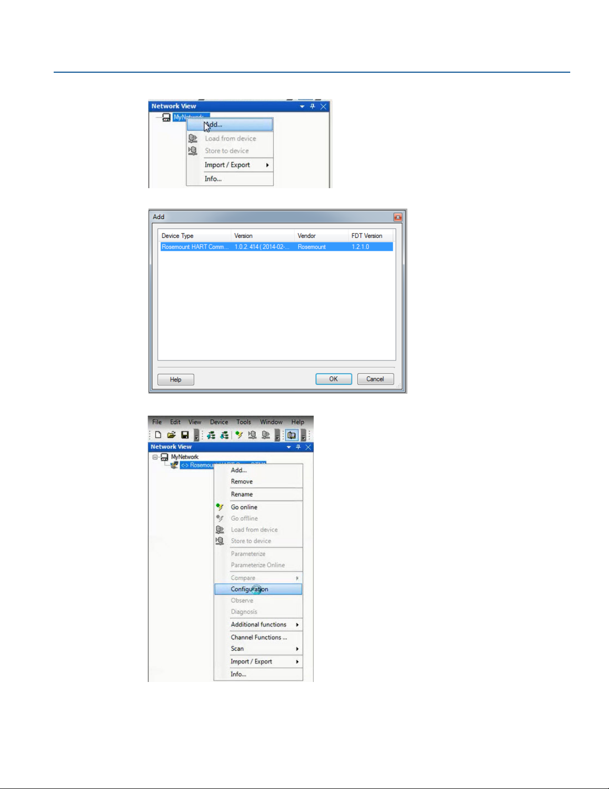
3. Right click My Network, and then select Add....
4. Select Rosemount HART CommDTM for Device Type and select OK.
5. Under MyNetwork, right click Rosemount HART CommDTM, then select Configuration.
6. Select the correct COM Port.
7. Select the Access Mode dropdown and set to Emulated.
6
Configuration

Reference Manual
A
B
C
D
OR
00809-0100-4088, Rev DB
8. Select Self Test to check the connection.
Configuration
April 2018
9. Select OK.
2.2.5 Connecting to a personal computer
Figure 2-1 shows how to connect a device to either a computer with the RTIS or a handheld
communicator.
Figure 2-1. Connecting a Personal Computer to a Transmitter
A. RTIS
B. HART modem
C. Field Communicator
D. User-provided power supply
Config uration
7

Configuration
April 2018
1. Wire the device as detailed in Section 3: Installation.
2. Connect the MACTek HART modem to the correct USB communications port on the PC as set up in
“Getting started with RTIS” on page 5.
3. Remove the cover of the transmitter above the side marked “FIELD TERMINALS.”
4. Connect the mini-grabber connectors to the “LOCAL (HART)” terminals.
Explosions can cause death or serious injury.
Do not remove the instrument cover in explosive atmospheres when the circuit is live.
2.3 Launching the configuration process
This section outlines how to configure the transmitter using the RTIS.
1. Right click Rosemount HART CommDTM, select Scan, then select Create Network.
Reference Manual
00809-0100-4088, Rev DB
8
Configuration

Reference Manual
00809-0100-4088, Rev DB
The DTM setup is complete.
2. Right click on the transmitter, then select Go Online. Your device is now online.
Configuration
April 2018
3. Right click on the transmitter again, select Parameterize Online, then select Configure/Setup.
Config uration
9

Configuration
April 2018
2.4 Basic device configuration
The Guided Setup section provides procedures to commission the transmitter. The Basic Setup button
can be used to perform all of the required transmitter configuration. See Table 2-2 on page 33 for the
complete list of Field Communicator for basic setup.
Figure 2-2. Guided Setup Tab
Reference Manual
00809-0100-4088, Rev DB
All screens in this section are shown for measurement type 1 (differential pressure, static pressure
[absolute], and process temperature) with LCD display. Field Communicator are given for a transmitter
with Measurement type 1. Field Communicator and screens for other multivariable types and
measurement types may vary.
Note
All screens in this section are shown using the RTIS. Edited information is not sent to the transmitter until
the Send button is selected.
2.4.1 Units of measure and damping
Fast Keys
The damping command changes the response time of the transmitter; higher values can smooth
variations in output readings caused by rapid input changes. Determine the appropriate damping setting
based on the necessary response time, signal stability, and other requirements. The damping command
utilizes floating point configuration allowing the user to input any damping value between 0 and 60
seconds.
The units and damping for each process variable may be edited by selecting Manual Setup in the menu
tree and then the appropriate tab as detailed below:
Under the Differential Pressure tab, the Units and Damping for the Differential Pressure may be edited.
Under the Static Pressure tab, the Units and Damping for the Static Pressure may be edited.
Units: 2, 1, 1, 2
Damping: 2, 1, 1, 3
10
Configuration

Reference Manual
00809-0100-4088, Rev DB
Note
Both absolute and gage pressure are available as variables. The type of transmitter ordered will
determine which variable is measured and which is calculated based on the user defined atmospheric
pressure. For more information on configuring the atmospheric pressure, see “Static pressure” on
page 16. Since only one of the static pressures is actually being measured, there is a single damping
setting for both variables which may be edited under the Static Pressure tab.
Under the Process Temperature tab, the Units and Damping for the Process Temperature may be edited.
Under the Module Temperature tab, the Units for the Module Temperature may be set. The sensor
module temperature measurement is taken within the module, near the differential pressure and/or
static pressure sensors and can be used to control heat tracing or diagnose device overheating.
2.4.2 Network
Configuration
April 2018
Fast Keys
2, 2, 6, 1
Device address
In the Network tab, the Device Address field can be used to set the device's address under the Modbus®
Configuration heading.
Figure 2-3. Network Tab
Config uration
Baud rates
The baud rate is user selectable under the Modbus Configuration heading.
For default and available baud rates, see “Baud rate (software configurable)” on page 57.
Turn around delay
The Turnaround Delay Time (ms) field can be used to configure the device’s turnaround delay time. For
more information, reference “Communications” on page 62.
11

Configuration
April 2018
2.5 Detailed device configuration
2.5.1 Display
Reference Manual
00809-0100-4088, Rev DB
Fast Keys
The LCD display features a four-line display. The first line of five characters displays the output
description, the second line of seven digits displays the actual value, and the third line of six characters
displays engineering units. The fourth line displays “Error” when there is a problem detected within the
transmitter. The LCD display can also display diagnostic messages. These diagnostic messages are listed
in “Alarms and conditions” on page 115.
The Display tab allows the user to configure which variables will be shown on the LCD display. Click the
check box next to each variable to select a variable for display. The transmitter will scroll through the
selected variables, showing each for three seconds as a default setting.
Figure 2-4. Display Tab
2, 2, 5
12
The Display tab includes three types of display options (information that appears on the LCD display)
including Device Variables, User-Defined Parameters, or User-Defined Variables.
Device variables
The device variables include Differential Pressure, Absolute Temperature, Gage Pressure, Process
Temperature, Module Temperature, Device Address or Baud Rate. These display variables can be selected
or deselected on the left column of the Display Options heading.
User-defined parameters
The User-Defined Parameters fields are for pieces of information the device can store for reference. The
device will not modify or update these parameters but they can be written by the user or a host system to
be displayed on the LCD display and include Beta Ratio, Pipe Schedule, or Orifice Bore. If the device loses
power at any point during operation, these values are stored in memory and will not be lost.
Configuration

Reference Manual
00809-0100-4088, Rev DB
To configure User-Defined Parameters, select Configure User-Defined Parameters.
A screen will appear as shown below:
Each parameter can be given a label, value and unit to be stored inside the device.
Configuration
April 2018
User-defined variables
Note
Only the value of the user-defined variables should be written on a periodic basis. Regular writes to the
other parameters may cause the device memory to fail.
The User-Defined Variable fields are for pieces of information that the device can store for a live reference
of the application status or production levels, via Modbus. The device itself will not modify or update
these variables; rather this is intended to be a live value sent to the device from a host, such as a flow
computer or Remote Terminal Unit (RTU). This information can then be displayed on the device's LCD
display and include variables such as Last 24-Hours of Gas Volume or Instantaneous Flow Rate.
To configure User-Defined Variables, select Configure User-Defined Variables. A screen will appear as
shown below:
Config uration
13

Configuration
April 2018
Similar to the User-Defined Parameters screen, you can input a label and unit for each variable, however
the value will be written by the flow computer or host. The user must program the flow computer or host
separately to write the value to the device. If the device loses power at any point during operation, the
value will be lost, but the Label and Units will not be lost.
Note
If the transmitter is ordered without an LCD display, the User-Defined Parameters and User-Defined
Variables are still available but are configured through the User-Defined Data tab in Manual Setup rather
than accessing them through the Display tab.
LCD display scroll time
The LCD display scroll time controls the amount of time each variable is displayed on the LCD display.
2.5.2 Device information
Reference Manual
00809-0100-4088, Rev DB
Fast Keys
The Device Information tab displays the device identification information on one screen including tags,
model numbers and assembly information.
Figure 2-5. Device Information Tab
2, 2, 7
2.5.3 Overview variables
Fast Keys
The Overview Variables tab allows the user to set which variables are displayed on the RTIS Overview
screen.
14
2, 2, 8
Configuration

Reference Manual
00809-0100-4088, Rev DB
Figure 2-6. Overview Variables Tab
2.5.4 Alert setup
Configuration
April 2018
Fast Keys
The Alert Configuration tab is found under the Alert Setup menu of the device’s configuration menu. From
this tab, the user can configure upper and lower alert levels for each of the measured variables. This
includes the Differential Pressure, Static Pressure (Absolute or Gage), Module Temperature, or Process
Tem p er at ur e.
Figure 2-7. Alert Configuration Tab
2, 3
Config uration
15

Configuration
April 2018
2.6 Variable configuration
2.6.1 Differential pressure
Reference Manual
00809-0100-4088, Rev DB
Fast Keys
Note
For Differential pressure sensor calibration , see page 106.
Figure 2-8. Differential Pressure Tab
2, 2, 1
1. Under the Setup heading, edit the Units, Damping, and Low DP Cutoff as needed.
2. Under the Reading heading, view the Differential Pressure and status.
3. Under the Sensor Limits heading, view the Upper, Lower, and Minimum Span.
2.6.2 Static pressure
Fast Keys
Note
For Static pressure sensor calibration , see page 109.
16
2, 2, 2
Configuration

Reference Manual
00809-0100-4088, Rev DB
Figure 2-9. Static Pressure Tab
Configuration
April 2018
1. Under the Sensor Type heading, view whether the sensor is an Absolute Pressure Sensor or a Gage
Pressure Sensor.
2. Under the Setup heading for Static Pressure, edit the Units, Damping, and User-Defined Atmospheric
Pressure as needed.
3. Under the Absolute Pressure Setup and Gage Pressure Setup heading, view the Pressure, Status, Upper,
Lower, and Minimum Span for both Absolute and Gage Pressure respectively.
2.6.3 Process temperature
Fast Keys
Note
For Process temperature sensor calibration , see page 109.
2, 2, 3
Config uration
17

Configuration
April 2018
Reference Manual
00809-0100-4088, Rev DB
Figure 2-10. Process Temperature Tab
1. Under the Setup heading for Process Temperature, edit the Units, Damping, and Sensor Type as
needed.
Note
The Rosemount 4088 accepts either a 3-wire or 4-wire RTD sensor, which can be selected under Sensor
Type. Ensure the type of sensor being used is selected or an RTD Sensor Type Mismatch will occur. For
more information about wiring the RTD, see “Install optional process temperature input (Pt 100 RTD
Sensor)” on page 47.
2. Under the Reading heading, view the Process Temperature and status.
3. Select the Tem per at ur e Mode under the Mode Setup heading. See Ta bl e 2 -1 for mode types and
descriptions.
Table 2-1. Temperature Modes
Temperature mode Description
Normal
Backup
Fixed
The transmitter will only use the actual measured Process Temperature value. If the
temperature sensor fails, the transmitter process temperature will be NAN (not a
number).
The transmitter will use the actual measured Process Temperature value. If the
temperature sensor fails, the transmitter will use the value shown in the Fixed/Backup
Tem pera ture field.
The transmitter will always use the temperature value shown in the Fixed/Backup
Tem pera ture field.
18
The Rosemount 4088 accepts Callendar-Van Dusen constants from a calibrated RTD schedule and
generates a special custom curve to match that specific sensor resistance vs. temperature performance.
Configuration

Reference Manual
00809-0100-4088, Rev DB
Matching the specific sensor curve with the transmitter configuration enhances the temperature
measurement accuracy.
4. Under the Sensor Matching heading, view the Callendar-Van Dusen constants R0, A, B, and C. If the
Callendar-Van Dusen constants are known for the user’s specific Pt 100 RTD sensor, the constants R0,
A, B, and C may be edited by selecting the Callendar-Van Dusen Setup button and following the
on-screen prompts.
The user may also view the α, β, and d coefficients by selecting the View Alpha, Beta, Delta button. The
constants R0, α, β, and d may be edited by selecting the Callendar-Van Dusen Setup button and
following the on-screen prompts. To reset the transmitter to the IEC 751 Defaults, select the Reset to IEC
751 Defaults button.
5. Under the Process Temperature Sensor Limits heading, view and edit the Upper and Lower Sensor
Limits. Process Temperature Sensor Limits allow for early detection of RTD failures or abnormal
process conditions.
2.6.4 Module temperature
Configuration
April 2018
Fast Keys
The sensor module temperature variable is the measured temperature of the sensors and electronics
within the sensor module assembly. The module temperature value can be used to control heat tracing
or diagnose device overheating.
Figure 2-11. Module Temperature Tab
2, 2, 4
Config uration
1. Under the Setup heading, edit the Units as needed.
2. Under the Reading heading, view the Module Temperature and status.
3. After the Sensor Limits heading, view the Upper and Lower Module Temperature Limits.
19

Configuration
April 2018
2.7 Menu trees and Field Communicator
Based on the configuration ordered, some measurements (i.e. static pressure, process temperature) may
not be available. Available measurements are determined by the Multivariable Type and Measurement
Type codes ordered. See ordering information in the Product Data Sheet for more information.
The menu trees and Field Communicator in this section are shown for the following model code:
Measurement type 1 (differential pressure, static pressure [absolute], process temperature) with LCD
display
The menu trees and Field Communicator for other model codes will vary.
Reference Manual
00809-0100-4088, Rev DB
20
Configuration

Reference Manual
00809-0100-4088, Rev DB
2.7.1 Rosemount 4088A menu tree
Figure 2-12. Overview
Configuration
April 2018
Config uration
21

Configuration
April 2018
Figure 2-13. Configure – Guided Setup
Reference Manual
00809-0100-4088, Rev DB
22
Configuration
 Loading...