

Manual: Rosemount 3244MV MultiVariable™ Temperature Transmitter with FOUNDATION™ Fieldbus
Table of contents
 Loading...
Rosemount Manual: Rosemount 3244MV MultiVariable™ Temperature Transmitter with FOUNDATION™ Fieldbus Manuals & Guides

00809-0100-4769
Product Discontinued
Model 3244MV MultiVariable™
Temperature Transmitter with
FOUNDATION™ Fieldbus
(Device Revision 3)
English
Rev. BA


яюэьыъщшчцхыцф
Model 3244MV MultiV a riable
Temperature Transmitter
with F
(Device Revision 3)
OUNDATION
™
fieldbus
NOTICE
Read this manual before working with the product. For personal and system safety, and for
optimum product performance, make sure you thoroughly understand t he contents before
installing,using or maintaining the this product.
In the United States, Rosemount Inc. has two toll-free assistance numbers
Customer Central:
Technical Supp ort, quoting, and or de r-related quest ions
1–800–999–9307 (7:00 a.m. to 7:00 p.m. CST)
North American Resp onse Cen ter:
Equipment service needs.
1–800–654–7768 (24 hours a day–includesCanada)
Outside of the United States, contact your local Rosemount
®
Sales Representative.
Rosemount Inc.
8200 Market Boulevard
Chanhassen, MN 55317 USA
Tel 1-800-999-9307
Fax (952) 949-7001
© 2000 Rosemount Inc.
Fisher-Rosemount Limited
Heath Place
Bognor Regis
West Sussex PO22 9SH
England
Tel 44 (1243) 863 121
Fax 44 (1243) 867 5541
Fisher-Rosemount
Singapore Pte Ltd.
1 Pandan Crescent
Singapore 128461
Tel (65) 777-8211
Fax (65) 770-8007
Email: AP.RMT-Specialist@frco.com
00809-0100-4769
© Rosemount Inc. 2000.
http://www.rosemount.com
The productsdescribedin this document are NOT designedfor nuclear-qualifiedapplicants.
Using non-nuclear qualified products in application that require nuclear-qualified hardware or
products may cause inaccurate readings.
For information on Rosemount nuclear-qualified products, contact you local Rosemount
Sales Representative.
NOTE:
We are very interested in your comments and suggestions on how we can
improve this product manual for the Rosemount
MuliVariable Temperature Transmitter with F
®
Model 3244MV
OUNDATION fieldbus.
Please send your comments and suggestions to the following E-Mail address
EdenPrairie.RMD-3244MVFManual@frco.com
Rosemount Model 3244MV MultiVariable Temperature Transmitter with F
protected by one or more U.S. Patents Pending. Other foreign patents pending.
Rosemount, the Rosemount logotype and Hot Backup are registered trademarks of Rosemount Inc.
Tri-Loop,MultiVariable and Complete Point Solutions is a trademark of Rosemount Inc.
PlantWeb and the PlantWeb logotype are trademarks of Fisher-Rosemount
Minigrabber is a trademark of Pomona Electronics.
Inconel is a registered trademark of International Nickel Co.
OUNDATION
F
Teflon is a registered trademark of E.I. du Pont de Nemours & Co.
COVER PHOTO: 3244-32442901
T
N
I
E
D
R
P
IN
U.
A.
S.
is a trademark of the Fieldbus Foundation
Fisher-Rosemount satisfies
all obligations coming from
legislation to harmonize
product requirements
in the European Union.
OUNDATION
fieldbus may be

Rosemount Model 3244MV MultiVariable Temperature Transmitter with FOUNDATION fieldbus
-2

Table of Contents
SECTION 1
Introduction
SECTION 2
Installation
Using this Manual . . . . . . . . . . . . . . . . . . . . . . . . . . . . . . . . . . . . . . . .1-1
Safety Messages. . . . . . . . . . . . . . . . . . . . . . . . . . . . . . . . . . . . . . . . . .1-2
Transmitter Overview . . . . . . . . . . . . . . . . . . . . . . . . . . . . . . . . . . . . .1-2
Foundation fieldbus Technology Overview . . . . . . . . . . . . . . . . . . . .1-3
Overview. . . . . . . . . . . . . . . . . . . . . . . . . . . . . . . . . . . . . . . . . . . . . . . . 2-1
Safety Messages. . . . . . . . . . . . . . . . . . . . . . . . . . . . . . . . . . . . . . . . . .2-1
Warnings . . . . . . . . . . . . . . . . . . . . . . . . . . . . . . . . . . . . . . . . . . . . . . .2-1
General Considerations. . . . . . . . . . . . . . . . . . . . . . . . . . . . . . . . . . . .2-2
Electrical Considerations . . . . . . . . . . . . . . . . . . . . . . . . . . . . . . . . . .2-2
Power Supply . . . . . . . . . . . . . . . . . . . . . . . . . . . . . . . . . . . . . . . . .2-2
Power Filter . . . . . . . . . . . . . . . . . . . . . . . . . . . . . . . . . . . . . . . . . . 2-2
Field Wiring . . . . . . . . . . . . . . . . . . . . . . . . . . . . . . . . . . . . . . . . . .2-2
Grounding . . . . . . . . . . . . . . . . . . . . . . . . . . . . . . . . . . . . . . . . . . . .2-4
Surges/Transients. . . . . . . . . . . . . . . . . . . . . . . . . . . . . . . . . . . . . .2-5
Switches . . . . . . . . . . . . . . . . . . . . . . . . . . . . . . . . . . . . . . . . . . . . . . . .2-5
Security . . . . . . . . . . . . . . . . . . . . . . . . . . . . . . . . . . . . . . . . . . . . . .2-5
Simulate . . . . . . . . . . . . . . . . . . . . . . . . . . . . . . . . . . . . . . . . . . . . .2-5
Sensor Connections . . . . . . . . . . . . . . . . . . . . . . . . . . . . . . . . . . . . . . .2-5
RTD or Ohm Inputs . . . . . . . . . . . . . . . . . . . . . . . . . . . . . . . . . . . . 2-6
Thermocouple or Millivolt Inputs . . . . . . . . . . . . . . . . . . . . . . . . .2-6
Mechanical Considerations . . . . . . . . . . . . . . . . . . . . . . . . . . . . . . . . .2-7
Installing the LCD Meter. . . . . . . . . . . . . . . . . . . . . . . . . . . . . . . .2-7
Mounting. . . . . . . . . . . . . . . . . . . . . . . . . . . . . . . . . . . . . . . . . . . . .2-8
Access Requirements . . . . . . . . . . . . . . . . . . . . . . . . . . . . . . . . . . .2-8
Tagging . . . . . . . . . . . . . . . . . . . . . . . . . . . . . . . . . . . . . . . . . . . . . .2-9
Environmental Considerations. . . . . . . . . . . . . . . . . . . . . . . . . . . . .2-10
Temperature Effects. . . . . . . . . . . . . . . . . . . . . . . . . . . . . . . . . . .2-10
Moist or Corrosive Environments . . . . . . . . . . . . . . . . . . . . . . . .2-11
Hazardous Location Installations . . . . . . . . . . . . . . . . . . . . . . . .2-12
Installation Procedures . . . . . . . . . . . . . . . . . . . . . . . . . . . . . . . . . . .2-13
Typical North American Configuration. . . . . . . . . . . . . . . . . . . .2-14
Typical European Configuration . . . . . . . . . . . . . . . . . . . . . . . . . 2-15
1

Rosemount Model 3244MV MultiVariable Temperature Transmitter with Foundation Fieldbus
SECTION 3
Operation
SECTION 4
Transducer Block
Device Tag and Node Address. . . . . . . . . . . . . . . . . . . . . . . . . . . . . . .3-2
Temperature Specific Block Configuration . . . . . . . . . . . . . . . . . . . .3-2
Transducer Block . . . . . . . . . . . . . . . . . . . . . . . . . . . . . . . . . . . . . .3-2
Back-up LAS. . . . . . . . . . . . . . . . . . . . . . . . . . . . . . . . . . . . . . . . . .3-3
Analog Input Function Block. . . . . . . . . . . . . . . . . . . . . . . . . . . . .3-3
Input Selector Function Block . . . . . . . . . . . . . . . . . . . . . . . . . . . .3-3
Configuring Links and Scheduling Block Execution . . . . . . . . . . . . .3-4
Hot Backup Configuration (option code U1) . . . . . . . . . . . . . . . . .3-5
Two Independent Sensors Configuration
(option code U4) . . . . . . . . . . . . . . . . . . . . . . . . . . . . . . . . . . . . . . .3-6
Differential Temperature Configuration
(option code U5) . . . . . . . . . . . . . . . . . . . . . . . . . . . . . . . . . . . . . . .3-7
Average Temperature Configuration (Option Code U6). . . . . . . .3-7
First Good Temperature Configuration (Option Code U7). . . . . . 3-7
Minimum Temperature Configuration (Option Code U8) . . . . . .3-7
Maximum Temperature Configuration (Option Code U9) . . . . . .3-8
Single Sensor Configuration (standard) . . . . . . . . . . . . . . . . . . . .3-9
Critical Control Application. . . . . . . . . . . . . . . . . . . . . . . . . . . . . .3-9
Overview. . . . . . . . . . . . . . . . . . . . . . . . . . . . . . . . . . . . . . . . . . . . . . . . 4-1
Definition . . . . . . . . . . . . . . . . . . . . . . . . . . . . . . . . . . . . . . . . . . . .4-1
Channel Definitions . . . . . . . . . . . . . . . . . . . . . . . . . . . . . . . . . . . .4-1
Parameters and Descriptions. . . . . . . . . . . . . . . . . . . . . . . . . . . . .4-2
Block/Transducer Errors . . . . . . . . . . . . . . . . . . . . . . . . . . . . . . . .4-5
Diagnostics . . . . . . . . . . . . . . . . . . . . . . . . . . . . . . . . . . . . . . . . . . . 4-6
Modes. . . . . . . . . . . . . . . . . . . . . . . . . . . . . . . . . . . . . . . . . . . . . . . .4-7
Alarm Detection . . . . . . . . . . . . . . . . . . . . . . . . . . . . . . . . . . . . . . .4-7
Status Handling . . . . . . . . . . . . . . . . . . . . . . . . . . . . . . . . . . . . . . .4-7
Transmitter- Sensor Matching . . . . . . . . . . . . . . . . . . . . . . . . . . . 4-7
Methods. . . . . . . . . . . . . . . . . . . . . . . . . . . . . . . . . . . . . . . . . . . . . .4-8
Troubleshooting . . . . . . . . . . . . . . . . . . . . . . . . . . . . . . . . . . . . . . . . . . 4-9
SECTION 5
Resource Block
SECTION 6
Maintenance
Overview. . . . . . . . . . . . . . . . . . . . . . . . . . . . . . . . . . . . . . . . . . . . . . . . 5-1
Definition . . . . . . . . . . . . . . . . . . . . . . . . . . . . . . . . . . . . . . . . . . . . . . .5-1
Parameters and Descriptions . . . . . . . . . . . . . . . . . . . . . . . . . . . . . . .5-1
Block Errors . . . . . . . . . . . . . . . . . . . . . . . . . . . . . . . . . . . . . . . . . .5-4
Modes. . . . . . . . . . . . . . . . . . . . . . . . . . . . . . . . . . . . . . . . . . . . . . . .5-4
Alarm Detection . . . . . . . . . . . . . . . . . . . . . . . . . . . . . . . . . . . . . . .5-5
Status Handling . . . . . . . . . . . . . . . . . . . . . . . . . . . . . . . . . . . . . . .5-5
LCD Meter Display. . . . . . . . . . . . . . . . . . . . . . . . . . . . . . . . . . . . . 5-5
Troubleshooting . . . . . . . . . . . . . . . . . . . . . . . . . . . . . . . . . . . . . . . . . . 5-6
Overview. . . . . . . . . . . . . . . . . . . . . . . . . . . . . . . . . . . . . . . . . . . . . . . . 6-1
Safety Messages. . . . . . . . . . . . . . . . . . . . . . . . . . . . . . . . . . . . . . . . . .6-1
Warnings. . . . . . . . . . . . . . . . . . . . . . . . . . . . . . . . . . . . . . . . . . . . .6-1
Hardware Diagnostics. . . . . . . . . . . . . . . . . . . . . . . . . . . . . . . . . . . . .6-2
Hardware Maintenance. . . . . . . . . . . . . . . . . . . . . . . . . . . . . . . . . . . .6-2
Sensor Checkout . . . . . . . . . . . . . . . . . . . . . . . . . . . . . . . . . . . . . . .6-2
Assembling the Electronics Housing . . . . . . . . . . . . . . . . . . . . . . .6-4
2

Table of Contents
SECTION 7
Specifications and
Reference Data
Overview. . . . . . . . . . . . . . . . . . . . . . . . . . . . . . . . . . . . . . . . . . . . . . . . 7-1
Functional Specifications . . . . . . . . . . . . . . . . . . . . . . . . . . . . . . . . . .7-1
Inputs . . . . . . . . . . . . . . . . . . . . . . . . . . . . . . . . . . . . . . . . . . . . . . . 7-1
Outputs . . . . . . . . . . . . . . . . . . . . . . . . . . . . . . . . . . . . . . . . . . . . . .7-1
Isolation. . . . . . . . . . . . . . . . . . . . . . . . . . . . . . . . . . . . . . . . . . . . . .7-1
Power Supply . . . . . . . . . . . . . . . . . . . . . . . . . . . . . . . . . . . . . . . . .7-1
Local Display. . . . . . . . . . . . . . . . . . . . . . . . . . . . . . . . . . . . . . . . . .7-1
Temperature Limits . . . . . . . . . . . . . . . . . . . . . . . . . . . . . . . . . . . . 7-2
Alarms. . . . . . . . . . . . . . . . . . . . . . . . . . . . . . . . . . . . . . . . . . . . . . .7-2
Status . . . . . . . . . . . . . . . . . . . . . . . . . . . . . . . . . . . . . . . . . . . . . . .7-2
Humidity Limits . . . . . . . . . . . . . . . . . . . . . . . . . . . . . . . . . . . . . . .7-2
Turn-on Time . . . . . . . . . . . . . . . . . . . . . . . . . . . . . . . . . . . . . . . . .7-2
Update Time . . . . . . . . . . . . . . . . . . . . . . . . . . . . . . . . . . . . . . . . . .7-2
Foundation Fieldbus Specifications. . . . . . . . . . . . . . . . . . . . . . . .7-3
Hazardous Locations Certifications. . . . . . . . . . . . . . . . . . . . . . . .7-3
Performance Specifications . . . . . . . . . . . . . . . . . . . . . . . . . . . . . . . . . 7-5
Accuracy . . . . . . . . . . . . . . . . . . . . . . . . . . . . . . . . . . . . . . . . . . . . .7-5
Stability. . . . . . . . . . . . . . . . . . . . . . . . . . . . . . . . . . . . . . . . . . . . . .7-5
RFI Effect . . . . . . . . . . . . . . . . . . . . . . . . . . . . . . . . . . . . . . . . . . . .7-5
Vibration Effect. . . . . . . . . . . . . . . . . . . . . . . . . . . . . . . . . . . . . . . . 7-5
Self Calibration. . . . . . . . . . . . . . . . . . . . . . . . . . . . . . . . . . . . . . . . 7-5
Ambient Temperature Effect . . . . . . . . . . . . . . . . . . . . . . . . . . . . .7-5
Physical Specifications . . . . . . . . . . . . . . . . . . . . . . . . . . . . . . . . . . . .7-5
Conduit Connections . . . . . . . . . . . . . . . . . . . . . . . . . . . . . . . . . . .7-5
Materials of Construction. . . . . . . . . . . . . . . . . . . . . . . . . . . . . . . .7-5
Mounting. . . . . . . . . . . . . . . . . . . . . . . . . . . . . . . . . . . . . . . . . . . . .7-6
Weight . . . . . . . . . . . . . . . . . . . . . . . . . . . . . . . . . . . . . . . . . . . . . . .7-6
Enclosure Ratings. . . . . . . . . . . . . . . . . . . . . . . . . . . . . . . . . . . . . .7-6
Reference Data. . . . . . . . . . . . . . . . . . . . . . . . . . . . . . . . . . . . . . . . . . . 7-7
Transmitter Dimensional Drawings. . . . . . . . . . . . . . . . . . . . . . . . . .7-9
Ordering Information . . . . . . . . . . . . . . . . . . . . . . . . . . . . . . . . . . . .7-11
Spare Parts List. . . . . . . . . . . . . . . . . . . . . . . . . . . . . . . . . . . . . . . . .7-13
SECTION 8
Hazardous Area Approval
Installation Drawings
Overview. . . . . . . . . . . . . . . . . . . . . . . . . . . . . . . . . . . . . . . . . . . . . . . . 8-1
3

Rosemount Model 3244MV MultiVariable Temperature Transmitter with Foundation Fieldbus
SECTION 9
Options
Overview. . . . . . . . . . . . . . . . . . . . . . . . . . . . . . . . . . . . . . . . . . . . . . . . 9-1
Safety Messages. . . . . . . . . . . . . . . . . . . . . . . . . . . . . . . . . . . . . . . . . .9-1
Warnings. . . . . . . . . . . . . . . . . . . . . . . . . . . . . . . . . . . . . . . . . . . . .9-1
Option Descriptions . . . . . . . . . . . . . . . . . . . . . . . . . . . . . . . . . . . . . . .9-1
Basic Control
(option code A01). . . . . . . . . . . . . . . . . . . . . . . . . . . . . . . . . . . . . . .9-1
Regulatory Control Suite
(option code B01). . . . . . . . . . . . . . . . . . . . . . . . . . . . . . . . . . . . . . .9-1
Mounting Brackets
(option codes B4 and B5) . . . . . . . . . . . . . . . . . . . . . . . . . . . . . . . .9-1
LCD Meter (Option Code M5) . . . . . . . . . . . . . . . . . . . . . . . . . . . .9-2
External Ground Lug Assembly (option code G1). . . . . . . . . . . . .9-2
Transient Protection (option code T1) . . . . . . . . . . . . . . . . . . . . . .9-2
Hot Backup (option code U1) . . . . . . . . . . . . . . . . . . . . . . . . . . . . . 9-3
Two Independent Sensors (option code U4) . . . . . . . . . . . . . . . . .9-3
Average Temperature (option code U6). . . . . . . . . . . . . . . . . . . . . 9-6
First Good Temperature (option code U7). . . . . . . . . . . . . . . . . . .9-6
Minimum Temperature
(option code U8) . . . . . . . . . . . . . . . . . . . . . . . . . . . . . . . . . . . . . . .9-6
Maximum Temperature
(option code U9) . . . . . . . . . . . . . . . . . . . . . . . . . . . . . . . . . . . . . . .9-6
Custom Transmitter Configuration (option code C1) . . . . . . . . . .9-7
Trim to Specific Rosemount RTD Calibration Schedule (Transmitter-
Sensor Matching) (option code C2) . . . . . . . . . . . . . . . . . . . . . . . .9-7
Five Point Calibration (option code C4) . . . . . . . . . . . . . . . . . . . .9-7
Trim to Special non-Standard Sensor (option code C7) . . . . . . . .9-7
50 Hz Line Voltage Filter (option code F5) . . . . . . . . . . . . . . . . . . 9-7
Assembly Options (option codes X1, X2, and X3) . . . . . . . . . . . . .9-8
Calibration Certificate (option code Q4) . . . . . . . . . . . . . . . . . . . . 9-8
APPENDIX A
Foundation™Fieldbus
Technology
Overview. . . . . . . . . . . . . . . . . . . . . . . . . . . . . . . . . . . . . . . . . . . . . . . A-1
Introduction . . . . . . . . . . . . . . . . . . . . . . . . . . . . . . . . . . . . . . . . . . . . A-1
Function Blocks . . . . . . . . . . . . . . . . . . . . . . . . . . . . . . . . . . . . . . A-1
Device Descriptions . . . . . . . . . . . . . . . . . . . . . . . . . . . . . . . . . . . A-2
Block Operation . . . . . . . . . . . . . . . . . . . . . . . . . . . . . . . . . . . . . . . . . A-3
Instrument- Specific Function Blocks . . . . . . . . . . . . . . . . . . . . . A-3
Alerts. . . . . . . . . . . . . . . . . . . . . . . . . . . . . . . . . . . . . . . . . . . . . . . A-3
Network communication . . . . . . . . . . . . . . . . . . . . . . . . . . . . . . . . . . A-3
Link Active Scheduler (LAS) . . . . . . . . . . . . . . . . . . . . . . . . . . . . A-4
Device Addressing . . . . . . . . . . . . . . . . . . . . . . . . . . . . . . . . . . . . A-5
Scheduled Transfers. . . . . . . . . . . . . . . . . . . . . . . . . . . . . . . . . . . A-5
Unscheduled Transfers . . . . . . . . . . . . . . . . . . . . . . . . . . . . . . . . A-6
Function Block Scheduling. . . . . . . . . . . . . . . . . . . . . . . . . . . . . . A-7
LAS Parameters . . . . . . . . . . . . . . . . . . . . . . . . . . . . . . . . . . . . . . A-7
Troubleshooting . . . . . . . . . . . . . . . . . . . . . . . . . . . . . . . . . . . . . . . . . A-9
4

Table of Contents
APPENDIX B
Analog Input
Function Block
APPENDIX C
Input Selector Function
Block
APPENDIX D
PID Function Block
Simulation. . . . . . . . . . . . . . . . . . . . . . . . . . . . . . . . . . . . . . . . . . . B-3
Filtering. . . . . . . . . . . . . . . . . . . . . . . . . . . . . . . . . . . . . . . . . . . . . B-4
Signal Conversion. . . . . . . . . . . . . . . . . . . . . . . . . . . . . . . . . . . . . B-5
Block Errors . . . . . . . . . . . . . . . . . . . . . . . . . . . . . . . . . . . . . . . . . B-6
Modes. . . . . . . . . . . . . . . . . . . . . . . . . . . . . . . . . . . . . . . . . . . . . . . B-6
Alarm Detection . . . . . . . . . . . . . . . . . . . . . . . . . . . . . . . . . . . . . . B-6
Status Handling . . . . . . . . . . . . . . . . . . . . . . . . . . . . . . . . . . . . . . B-7
Advanced Features . . . . . . . . . . . . . . . . . . . . . . . . . . . . . . . . . . . . B-8
Application Information. . . . . . . . . . . . . . . . . . . . . . . . . . . . . . . . B-8
Troubleshooting . . . . . . . . . . . . . . . . . . . . . . . . . . . . . . . . . . . . . . . . B-12
Block Errors . . . . . . . . . . . . . . . . . . . . . . . . . . . . . . . . . . . . . . . . . C-3
Modes. . . . . . . . . . . . . . . . . . . . . . . . . . . . . . . . . . . . . . . . . . . . . . . C-3
Alarm Detection . . . . . . . . . . . . . . . . . . . . . . . . . . . . . . . . . . . . . . C-4
Block Execution . . . . . . . . . . . . . . . . . . . . . . . . . . . . . . . . . . . . . . C-4
Status Handling . . . . . . . . . . . . . . . . . . . . . . . . . . . . . . . . . . . . . . C-5
Application Information. . . . . . . . . . . . . . . . . . . . . . . . . . . . . . . . C-5
Troubleshooting . . . . . . . . . . . . . . . . . . . . . . . . . . . . . . . . . . . . . . . . . C-6
Setpoint Selection and Limiting . . . . . . . . . . . . . . . . . . . . . . . . . . . . D-5
Filtering. . . . . . . . . . . . . . . . . . . . . . . . . . . . . . . . . . . . . . . . . . . . . D-6
Feedforward Calculation . . . . . . . . . . . . . . . . . . . . . . . . . . . . . . . D-6
Tracking . . . . . . . . . . . . . . . . . . . . . . . . . . . . . . . . . . . . . . . . . . . . D-6
Output Selection and Limiting . . . . . . . . . . . . . . . . . . . . . . . . . . D-6
Bumpless Transfer and Setpoint Tracking . . . . . . . . . . . . . . . . . D-6
PID Equation Structures . . . . . . . . . . . . . . . . . . . . . . . . . . . . . . . D-7
Reverse and Direct Action . . . . . . . . . . . . . . . . . . . . . . . . . . . . . . D-7
Reset Limiting . . . . . . . . . . . . . . . . . . . . . . . . . . . . . . . . . . . . . . . D-7
Block Errors . . . . . . . . . . . . . . . . . . . . . . . . . . . . . . . . . . . . . . . . . D-8
Modes. . . . . . . . . . . . . . . . . . . . . . . . . . . . . . . . . . . . . . . . . . . . . . . D-8
Alarm Detection . . . . . . . . . . . . . . . . . . . . . . . . . . . . . . . . . . . . . . D-9
Status Handling . . . . . . . . . . . . . . . . . . . . . . . . . . . . . . . . . . . . . . D-9
Application Information . . . . . . . . . . . . . . . . . . . . . . . . . . . . . . . D-10
Troubleshooting . . . . . . . . . . . . . . . . . . . . . . . . . . . . . . . . . . . . . . . . D-15
APPENDIX E
Arithmetic Function Block
APPENDIX F
Signal Characterizer
Function Block
Block Errors . . . . . . . . . . . . . . . . . . . . . . . . . . . . . . . . . . . . . . . . . E-4
Modes. . . . . . . . . . . . . . . . . . . . . . . . . . . . . . . . . . . . . . . . . . . . . . . E-4
Alarm Detection . . . . . . . . . . . . . . . . . . . . . . . . . . . . . . . . . . . . . . E-5
Block Execution . . . . . . . . . . . . . . . . . . . . . . . . . . . . . . . . . . . . . . E-5
Status Handling . . . . . . . . . . . . . . . . . . . . . . . . . . . . . . . . . . . . . . E-5
Application Information. . . . . . . . . . . . . . . . . . . . . . . . . . . . . . . . E-6
Advanced Topics . . . . . . . . . . . . . . . . . . . . . . . . . . . . . . . . . . . . . . E-7
Troubleshooting . . . . . . . . . . . . . . . . . . . . . . . . . . . . . . . . . . . . . . . . . E-8
Block Errors . . . . . . . . . . . . . . . . . . . . . . . . . . . . . . . . . . . . . . . . . .F-3
Modes. . . . . . . . . . . . . . . . . . . . . . . . . . . . . . . . . . . . . . . . . . . . . . . .F-3
Alarm Detection . . . . . . . . . . . . . . . . . . . . . . . . . . . . . . . . . . . . . . .F-3
Block Execution . . . . . . . . . . . . . . . . . . . . . . . . . . . . . . . . . . . . . . .F-4
Block Errors . . . . . . . . . . . . . . . . . . . . . . . . . . . . . . . . . . . . . . . . . .F-5
Status Handling . . . . . . . . . . . . . . . . . . . . . . . . . . . . . . . . . . . . . . .F-5
Application Information . . . . . . . . . . . . . . . . . . . . . . . . . . . . . . . . .F-6
Troubleshooting . . . . . . . . . . . . . . . . . . . . . . . . . . . . . . . . . . . . . . . . . .F-6
5

Rosemount Model 3244MV MultiVariable Temperature Transmitter with Foundation Fieldbus
APPENDIX G
Operation with FisherRosemount®DeltaV
™
APPENDIX H
European ATEX Directive
Information
Introduction . . . . . . . . . . . . . . . . . . . . . . . . . . . . . . . . . . . . . . . . . . . . G-1
About DeltaV Software with AMSinside. . . . . . . . . . . . . . . . . . . G-1
Software Functionality . . . . . . . . . . . . . . . . . . . . . . . . . . . . . . . . . . . G-1
Configure the Model 3244MV . . . . . . . . . . . . . . . . . . . . . . . . . . . G-2
Configure the Loop. . . . . . . . . . . . . . . . . . . . . . . . . . . . . . . . . . . . . . . G-5
Create a Device Profile. . . . . . . . . . . . . . . . . . . . . . . . . . . . . . . . . G-5
Define the Control Strategy. . . . . . . . . . . . . . . . . . . . . . . . . . . . . G-7
Commission the Transmitter. . . . . . . . . . . . . . . . . . . . . . . . . . . . G-8
Set Transmitter Configuration Parameters . . . . . . . . . . . . . . . G-11
Download the Control Strategy to the Device. . . . . . . . . . . . . . G-13
CENELEC/BASEEFA . . . . . . . . . . . . . . . . . . . . . . . . . . . . . . . . . . . . H-1
Intrinsic Safety . . . . . . . . . . . . . . . . . . . . . . . . . . . . . . . . . . . . . . . H-1
CENELEC/BASEEFA Type N Approval. . . . . . . . . . . . . . . . . . . H-2
6

Section
1 Introduction
USING THIS MANUAL This manual is intended to assist in installing, operating, and
maintaining the Model 3244MV MultiVariable Temperature
Transmitters with F
Section 2: Installation
explains how to install the Model 3244MV by providing electrical,
mechanical, and environmental installation considerations.
Section 3: Operation
summarizes basic transmitter operation, software functionality, and
provides basic configuration procedures.
Section 4: Transducer Block
describes the Transducer Block and its operation.
Section 5: R esource Block
describes the Resource Block and its operation.
Section 6: Mai nten ance
OUNDATION™ fieldbus.
describes hardware diagnostics, maintenance tasks, and
hardware troubleshooting.
Section 7: Sp ecifications and Reference Data
lists functional, performance, and physical specification data for the
Model 3244MV temperature transmitter.
Section 8: Haz ardous Area Approval Installation Drawings
contains the installation drawings necessary to maintain certified
ratings for the Model 3244MV installed in hazardous locations.
Section 9: Options
presents options that can be ordered with the Model 3244MV.
Appendix A: Foundation™ Fieldbus Technology
describes the basic information about fieldbus and the function blocks
that are common to all fieldbus devices.
Appendix B: Analog Input Function Block
describes the operation and parameters of the Analog Input
function block.
Appendix C: Input Selector Function Block
describes the operation and parameters of the Input Selector
function block.
Appendix D: PID Function Block
describes the operation and parameters of the
Proportional/Integral/Derivative (PID) function block.
1-1

Rosemount Model 3244MV MultiVariable Temperature Transmitter with Foundation Fieldbus
Appendix E: Arithmetic Function Block
describes the operation and parameters of the Arithmetic
function block.
Appendix F: Signal Characteriz er Function Block
describes the operation and parameters of the Signal Characterizer
function block.
Appendix G: Operation with Fisher-Rosemount® DeltaV™
provides specific instructions for performing basic configuration
operations on the Model 3244MV Temperature Transmitter using the
Fisher-Rosemount DeltaV host software.
Appendix H: European ATEX Directive Information
provides information on European ATEX compliance.
SAFETY MESSAGES Procedures and instructions in this manual may require special
precautions to ensure the safety of the personnel performing the
operations. Information that raises potential safety issues is indicated
by a warning symbol ( ). Refer to the safety messages, listed at the
beginning of each section, before performing an operation preceded by
this symbol.
TRANSMITTER OVERVIEW Thank you for selecting the Rosemount Model 3244MV MultiVariable
Temperature Transmitter with F
you will find this to be the ultimate transmitter for measuring
temperature in your control, safety, and monitoring applications. This
transmitter is designed with unsurpassed quality and reliability that
you have come to expect from Rosemount Inc. The Model 3244MV is
among the world’s first devices to be registered with the Fieldbus
Foundation.
The enhanced measurement capability of the Model 3244MV allows it
to communicate multiple variables to a F
configuration tool. This temperature transmitter has the ability to
accept simultaneous inputs from two temperature sensing elements.
These two inputs can be used for control and safety applications, which
involve control, safety interlocks, or any type of critical monitoring
points where sensor redundancy is desirable. With a dual-element
sensor, the Model 3244MV Hot Backup
sensor redundancy in case the primary sensing element fails. In
addition, the differential temperature measurement capability can be
used as a diagnostic to detect sensor drift in a dual-element sensor. The
Model 3244MV MultiVariable Temperature Transmitter with
F
OUNDATION fieldbus combines the effects of transmitter drift, sensor
interchangeability error, temperature effects, and reference accuracy to
better account for actual process conditions and to assure
maximum accuracy.
OUNDATION fieldbus. We are confident
OUNDATION fieldbus host or
®
feature provides automatic
1-2

Introduction
The Rosemount Model 3244MV is excellent for measuring temperature
in monitoring applications involving basic process monitoring because
of the transmitter’s ability to simultaneously measure two separate and
independent temperature points with one transmitter. With this dual
input configuration, instrument costs can be reduced by as much as 50
percent. In addition, the multi-drop capability of F
results in additional savings through reduced wiring costs.
OUNDATION fieldbus
FOUNDATION FIELDBUS
TECHNOLOGY OVERVIEW
FOUNDATION fieldbus is an all digital, serial, two-way communication
system that interconnects field equipment such as sensors, actuators,
and controllers. Fieldbus is a Local Area Network (LAN) for
instruments that are used in both process and manufacturing
automation, having the built-in capability to distribute the control
application across the network. The fieldbus environment is the base
level group of digital networks in the hierarchy of plant networks.
The fieldbus retains the desirable features of the 4–20 mA analog
system, including standardized physical interface to the wire,
bus-powered devices on a single pair of wires, and intrinsic safety
options. It also enables the following capabilities:
• Increased capabilities due to full digital communication.
• Reduced wiring and wire terminations due to multiple devices on
one pair of wires.
• Increased supplier selection due to interoperability.
• Reduced loading on control room equipment due to the
distribution of some control and input/output functions to
field devices.
1-3

Rosemount Model 3244MV MultiVariable Temperature Transmitter with Foundation Fieldbus
1-4

Section
2 Installation
OVERVIEW This section contains specific information pertaining to the installation
of the Model 3244MV MultiVariable Temperature Transmitter with
F
OUNDATION fieldbus.
SAFETY MESSAGES Instructions and procedures in this section may require special
precautions to ensure the safety of the personnel performing the
operations. Information that raises potential safety issues is indicated
by a warning symbol ( ). Please refer to the following safety messages
before performing an operation preceded by this symbol.
WARNINGS
Explosions could result in death or serious injury:
• Do not remove the transmitter cover in explosive atmospheres
when the circuit is live.
• Verify that the operating atmosphere of the transmitter is consistent with the
appropriate hazardous locations certifications.
• Both transmitter covers must be fully engaged to meet
explosion-proofrequirements.
Electrical shock could cause death or seriousinjury. If the sensor is installedin a
high-voltage environment and a fault condition or installation error occurs, high voltage
may be present on transmitter leads and terminals.
• Use extremecautionwhen making contact with the leads and terminals.
Processleaks could result in death or serious injury:
• Installand tightenthermowellsor sensorsbeforeapplyingpressure, or process
leakage may result.
• Do not remove the thermowell whilein operation.Removing while in operation
maycause process fluid leaks.
Failure to follow these installation guidelines could result in death or serious injury:
• Make sure only qualified personnel perform the installation.
2-1

Rosemount Model 3244MV MultiVariable Temperature Transmitter with Foundation Fieldbus
GENERAL CONSIDERATIONS
ELECTRICAL CONSIDERATIONS
Electrical temperature sensors, such as RTDs and thermocouples,
produce low-level signals proportional to temperature. The Model
3244MV MultiVariable Temperature Transmitter converts the analog
sensor signal to a digital signal that is relatively insensitive to lead
length and electrical noise. This signal is then transmitted over the
F
OUNDATION fieldbus to the control room using two wires.
Proper electrical installation is necessary to prevent errors due to
sensor lead resistance and electrical noise. Shielded, twisted cable
produce the best results in electrically noisy environments. Figure 2-1
on page -3 shows a typical F
OUNDATION fieldbus installation.
Power Supply The transmitter requires between 9 and 32 V dc to operate and provide
complete functionality. The dc power supply should provide power with
less than 2% ripple.
Power Filter A fieldbus segment requires a power conditioner to isolate the power
supply filter and decouple the segment from other segments attached to
the same power supply.
Field Wiring All power to the transmitter is supplied over the signal wiring. Signal
wiring should be a shielded, twisted pair for best results. Do not run
unshielded signal wiring in conduit or open trays with power wiring or
near heavy electrical equipment.
If the sensor is installed in a high-voltage environment and a fault
condition or installation error occurs, the sensor leads and transmitter
terminals could carry lethal voltages. Use extreme caution when
making contact with the leads and terminals.
NOTE
Do not apply high voltage (e.g. ac line voltage) to the transmitter
terminals. Abnormally high voltage can damage the unit. Sensor and
transmitter power terminals are rated to 42.4 V dc.
2-2

Installation
Power Connections
Use copper wire of sufficient size to ensure that the voltage across the
transmitter power terminals is not below 9 V dc.
To connect power to the transmitter, follow the steps below:
1. Remove the transmitter cover to expose the transmitter terminal
block. Do not remove transmitter covers in explosive
atmospheres when the circuit is live.
2. Connect the power leads to the terminals marked “+” and “T” as
shown in Figure 2-2 on page -4. The power terminals are not
polar sensitive, meaning that the electrical polarity of the power
leads is not significant when connecting to the power terminals.
The use of crimped lugs is recommended when wiring to screw
terminals.
3. Tighten the terminal screws to ensure adequate contact. No
additional power wiring is needed.
4. Replace the transmitter cover, tightening the cover threads at
least one-third turn after the o-ring contacts the housing.
Both transmitter covers must be fully engaged to meet
explosion-proof requirements.
Figure 2-1. FOUNDATION
FieldbusInstallation
NOTE
After installation, it may take several seconds for the LCD meter to
function once power is applied to the transmitter.
Integrated
Power
Conditioner
and Filter
Power
Supply
(Thepower
supply,filter,first
terminator, and
configuration
toolare typically
located in the
control room.)
FOUNDATION
fieldbus
Configuration
Tool
6234 ft (1900 m) max
(depending upon cable characteristics)
Terminators
(Trunk)
(Spur)
(Spur)
Power/Signal
Wiring
* Intrinsic safe installations may allow fewer devices per I.S. barrier.
Devices 1
through 16
*
3144-3144_01C
2-3

Rosemount Model 3244MV MultiVariable Temperature Transmitter with Foundation Fieldbus
Figure 2- 2. Transmitter Ter minal Block
Sensor
Terminals
Power Terminals
(not polarity–sensitive)
Transmitter
Terminals
“T” and “+”
Ground
Terminal
Grounding Transmitters are electrically isolated to 500 V ac rms. If desired, you
can ground the signal wiring at any single point. When using a
grounded thermocouple, the grounded junction serves as this point.
NOTE
Do not ground the signal wire at both ends.
Shielded Wire
To avoid grounding the loop, the recommended grounding techniques
for shielded wire usually requires a single grounding point for each
shielded wire. The following examples illustrate the single grounding
point technique:
Example 1
Connect the shield for the signal wiring to the shield for the sensor
wiring. Verify that the two shields are tied together and electrically
isolated from the transmitter housing. Ground the shield at the
power supply end.
3144-0200E01C
2-4
Example 2
Connect the shield for the sensor wiring to the ground terminal,
which is located inside the terminal compartment of the transmitter
housing. The shield for the signal wiring should be cut and isolated
from the transmitter housing and should be grounded only at the
power supply end. Never connect the shield for the signal wiring to
the ground terminal inside the transmitter housing.
Transmitter Housing
Ground the transmitter housing in accordance with local electrical
requirements. An internal ground terminal is standard. If necessary, an
optional external ground lug assembly (option code G1) can be ordered.
An external ground lug is installed when ordering certain hazardous
locations approvals (see Figure 7-5 on page 7-10). External grounding
is recommended when using the optional transient protector
(option code T1).

Installation
Surges/Transients The transmitter will withstand the electrical transients of energy level
that usually occurs through static discharges or induced switching.
However, high-energy transients, such as those induced by lightning
strikes, can damage both the transmitter and the sensor.
To protect against high-energy transients, install the integral transient
protection board (option code T1). The integral transient protection board
is available as an ordered option or as an accessory. Refer to “Transient
Protection (option code T1)” on page 9-2 for more information.
SWITCHES
Security After configuring the transmitter, you may want to protect the
configuration data from unwarranted changes. Each transmitter is
equipped with a security switch that can be positioned “ON” to prevent
the accidental or deliberate change of configuration data. This switch is
located on the front side of the electronics module and is labeled
SECURITY (see Figure 2-3 on page -5).
Simulate The simulate switch is used in conjunction with the Analog Input (AI)
function block. This switch is used to simulate temperature
measurement and as a lock-out feature for the AI function block. To
enable the simulate feature, the switch must transition from “OFF” to
“ON” after power is applied to the transmitter. When the LCD meter is
installed, the simulate feature is enabled with a jumper (see Figure 2-3
on page 2-5). This feature prevents the transmitter from being left in
simulator mode.
Figure 2-3. Transmitter
Switch Locations.
.
Transmitter Electronics Modu le LCD Met er
Switches
ON OFF
Jumper
SENSOR CONNECTIONS The Model 3244MV is compatible with a number of RTD and
thermocouple sensor types. Figure 2-4 on page 2-6 shows the correct
input connections to the sensor terminals on the transmitter. To
ensure an adequate sensor connection, anchor the sensor lead wires
beneath the flat washer on the terminal screw. Do not remove the
transmitter cover in explosive atmospheres when the circuit is live.
Both transmitter covers must be fully engaged to meet
explosion-proof requirements.
ÿ
2-5

Rosemount Model 3244MV MultiVariable Temperature Transmitter with Foundation Fieldbus
If the sensor is installed in a high voltage environment and a fault
condition or installation error occurs, the sensor leads and transmitter
terminals could carry lethal voltages. Use extreme caution when
making contact with the leads and terminals.
RTD or Ohm Inputs Various RTD configurations, including 2-wire, 3-wire, 4-wire, and
compensation loop designs, are used in industrial applications. When
the transmitter is mounted remotely from a 3- or 4-wire RTD, it will
operate within specifications, without recalibration, for lead wire
resistances of up to 10 ohms per lead (equivalent to 1,000 feet of 20
AWG wire). In this case, the leads between the RTD and transmitter
should be shielded. When using only two leads (or a compensation loop
lead wire configuration), both RTD leads are in series with the sensor
element. Significant errors can occur if the lead lengths exceed one foot
of 20 AWG wire.
Thermocouple or
Millivolt Inputs
Figure 2-4. Transmitter Sensor
Wiring Diagram.
2-wire RTD
and Ohms
***
**
W
R
W&G
G
3-wire RTD
and Ohms**
For direct-mount applications, connect the thermocouple directly to the
transmitter. When mounting the transmitter remotely from the sensor,
use appropriate thermocouple extension wire. Make connections for
millivolt inputs with copper wire. Use shielding for long runs of wire.
NOTE
The use of two grounded thermocouples with the Model 3244MV is not
recommended. For applications in which the use of two thermocouples
is desired, connect either two ungrounded thermocouples, one grounded
and one ungrounded thermocouple, or one dual element thermocouple.
*
4-wire RTD
and Ohms
Thermocouples
and Millivolts
** ****
RTD with
Compensation Loop
Backup/Dual Sensor
* Transmitter must be configured for a 3-wire RTD in order to recognize an RTD with a compensation loop.
** Rosemount provides 4-wire sensors for all single-element RTDs. You can use these RTDs in 3-wire configurations by
*** Typicalwiring configurationof a Rosemount dual-element RTD is shown (R=Red, W=White, G=Green,B=Black
2-6
B
Average.
Temp./DT/Hot
with 2 RTDs
leaving the unneededleads disconnected and insulatedwith electricaltape.
Average.
Temp./DT/Hot
Backup/Dual Sensor
with 2 Thermocouples
Average. Temp./DT/
Hot Backup/Dual
Sensor with
RTDs/Thermocouples
Average. Temp./DT/
Hot Backup/Dual
Sensor with
RTDs/Thermocouples
Average. Temp./DT/
Hot Backup/Dual
Sensor with 2 RTDs
with Compensation
Loop
3144-0000F05A

Installation
MECHANICAL CONSIDERATIONS
Using an optional mounting bracket (see Figure 2-7 on page 2-10), you
can attach the Model 3244MV to:
• directly to a sensor
• apart from the sensor
• to a flat surface
• to a 2-inch diameter pipe
Installing the LCD Meter Transmitters ordered with the LCD meter option (option code M5) are
shipped with the meter installed. If later installation of the LCD meter
is desired, a small instrument screwdriver and a LCD meter with the
Meter Cover Kit are required (see “Spare Parts List” on page 7-13). The
Meter Cover Kit includes:
• LCD meter display
• Meter cover with o-ring in place
• Captive mounting screws (quantity 2)
• 10-pin interconnection header
To install the LCD Meter with Meter Cover Kit refer to Figure 2-5 and
Figure 2-7 while following the steps below.
1. Remove the transmitter cover to expose the transmitter
electronics. Do not remove the transmitter covers in explosive
atmospheres when the circuit is live.
2. Ensure that the transmitter SECURITY switch is set to the
“OFF” position.
3. Insert the long pins on the interconnection header into the
ten-pin socket located on the face of the electronics
module assembly.
4. Orient the LCD meter. The LCD meter can be rotated in
90-degree increments for easy viewing. Position one of the four
ten-pin sockets into the back of the meter to accept the
interconnection header. Insert the captive mounting screws into
the two holes on the meter that coincide with the appropriate
holes on the electronics module assembly.
5. Attach the meter to the electronics with the captive
mounting screws.
6. Insert the SIMULATE jumper into the three pin socket located
on the face of the meter.
7. Thread the meter cover onto the housing. Be sure to tighten the
cover threads at least one-third turn after the o-ring contacts the
housing. Both transmitter covers must be fully engaged to meet
explosion-proof requirements.
8. When power is applied to the transmitter, the LCD meter will
need to be configured by setting the DISPLAY_MODE parameter
(see Section 5: Resource Block for more details on configuring
the LCD meter).
2-7

Rosemount Model 3244MV MultiVariable Temperature Transmitter with Foundation Fieldbus
NOTE
Observe the following LCD meter temperature limits:
Operating: –4 to 185 °F (–20 to 85 °C)
Storage: –50 to 185 °F (–45 to 85 °C)
NOTE
Option code M5 can be added to the Model 3244MV Rev. 2 without
upgrading the device software.
Figure 2-5. Transmitter and Meter
Exploded View
Housing
10-pin Interconnection Header
Electronics
Module Assembly
LCD Meter Display
Meter Cover
Captive Mounting Screws
FIELDBUS-3244MV-0000A03A
Mounting The transmitter may require supplementary support under
high-vibration conditions, particularly if used with extensive
thermowell lagging or long extension fittings. Pipe stand mounting,
using one of the optional mounting brackets, is recommended for use in
high-vibration applications.
Access Requirements Take into account the need to access the transmitter when choosing an
installation location and position.
Housing Rotation
You may rotate the electronics housing up to 90 degrees in either
direction to improve field access to the two compartments.
Terminal Block Side of the Housing
Mount the transmitter so the terminal block side is accessible. Allow
adequate clearance for cover removal. Make wire connections through
the conduit openings on the bottom of the housing.
Electronics Side of the Housing
Mount the transmitter so the electronics-side is accessible. Provide
adequate clearance for cover removal and leave additional room if an
LCD meter is installed.
NOTE
If you consider adding a LCD Meter at a later date, the electronics-side
of the transmitter should be mounted in a visible position
2-8

Tagging Commissioning Tag
The transmitter has been supplied with a removable commissioning tag
that contains both the Device ID and a space to record the device tag.
The Device ID is a unique code that identifies a particular device in the
absence of a device tag. The device tag is used as an operational
identification for the device and is usually defined by the Piping and
Instrumentation Diagram (P & ID).
When commissioning more than one device on a fieldbus segment, it
can be difficult to identify which device is at a particular location. The
removable tag provided with the transmitter can aid in this process by
linking the Device ID and a physical location for each transmitter on
the segment. The installer should note the transmitter’s physical
location on both the removable commissioning tag and the bottom
portion of the tag, which can be torn off. The bottom portion of the tags
can be used for commissioning the segment in the control system.
Figure 2-6. Commissioning Tag
Installation
Device ID
DeviceTag to denote
physical location
FIELDBUS-3244MV-COMMTAG
2-9

Rosemount Model 3244MV MultiVariable Temperature Transmitter with Foundation Fieldbus
)
Figure 2-7.
Option Code B4 and B5
Mounting Bracket
Panel Mount PipeMount
3.65 ±0.06
(92.7)
Option C ode B4 Brack et
1.04 (26)
1.55
(39.4)
яюэьыъщющш
üþ
яющыъы щющш
ùþý
Note: Dimensionsare in inches (millimeters)
2 (51) D iameter
Washer (Provided)
6.6 (162.6
чюьцхыфутцщсующсыъяцыущыущэрцсыптушшутцьцясо
1.0
(25.4)
ùþüûüùþ
ùþøûþ
2-inch (50.8)Pipestand
3044-2101A01A, 3144-0427C, 0427B, 3144A 14A
Option C ode B5 Brack et
1.0 (25)
7.15 (181.6.5)
ÿ
ENVIRONMENTAL CONSIDERATIONS
Tem perature Effects See Table 2-1.
Aside from ambient temperature variations, process-induced
temperature in a direct mounting configuration is transferred from the
thermowell to the transmitter housing. If the expected process
temperature is near or beyond specification limits, consider using an
additional thermowell lagging, an extension nipple, or a remote
mounting configuration to isolate the transmitter from these excessive
temperatures. Figure 2-8 provides an example of the relationship
between transmitter housing temperature rise and extension length.
Use Figure 2-8 and the accompanying example to determine adequate
thermowell extension length.
2-10

TABLE 2-1. Temperature Ranges for
Transmitter Operation
Figure 2-8. Model 3244MV Transmitter
Housing Temperature Rise versus
Extension Length fora TestInstallation
Installation
With LCD Meter Without LCD Meter
–4 to 185 °F –40 to 185 °F
(–20 to 85 °C) (–40 to 85 °C)
60 (108)
50 (90)
40 (72)
HOUSING TEMPERATURE
RISE ABOVE AMBIENT °C (°F)
30 (54)
20 (36)
10 (18)
0
ÿ
ÿ
EXTENSION LENGTH (IN.)
EXAMPLE:
The maximum permissible housing temperature rise (T) can be
calculated by subtracting the maximum ambient temperature (A)
from the transmitter’s ambient temperature specification limit (S).
For instance, suppose A = 40 °C
T = S – A
T = 85 °C – 40 °C
T = 45 °C
For a process temperature of 540 °C, an extension length of 3.6
inches yields a housing temperature rise (R) of 22 °C, which provides
a safety margin of 23 °C. A six-inch extension length (R = 10 °C)
would offer a higher safety margin (35 °C) and would reduce
temperature-effect errors but would probably require extra support
for the transmitter. Gauge the requirements for individual
applications along this scale. If a thermowell with lagging is used,
the extension length may be reduced by the length of the lagging.
3044-0123A
Moist or Corros ive Environments
The Model 3244MV has a highly reliable, dual-compartment housing
designed to resist moisture and corrosives. The electronics module
assembly is mounted in a compartment that is isolated from the
terminal side conduit entries. When covers are installed correctly,
o-ring seals protect the interior of each compartment from the
environment. However, in humid environments it is possible for
moisture to accumulate in conduit lines and drain into the housing.
2-11
Rosemount Model 3244MV MultiVariable Temperature Transmitter with Foundation Fieldbus
Proper installation of the transmitter ensures maximum operation and
service life. It can also have a significant impact on preventing moisture
from accumulating in the housing. Refer to Figure 2-9 before mounting
the transmitter.
If possible, mount the transmitter at a high point in the conduit run so
moisture from the conduits will not drain into the housing. If the
transmitter is mounted at a low point, the terminal compartment could
fill with water. In some instances the installation of a poured conduit
seal, such as the one pictured in Figure 2-10, is advisable. Periodically
remove the terminal compartment cover and inspect the transmitter for
moisture and corrosion.
Figure 2-9. IncorrectConduit
Installation
Figure 2- 10. Process Mounting with
Drain Seal
Hazardous Location Installations
Sealing
Compound
Conduit for
Field Wiring
Thermowell
Poured
Conduit Seal
Sensor Hex
Union Coupling
with Extension
(Where Required)
The Model 3244MV is designed with an explosion-proof housing and
circuitry suitable for intrinsically safe and non-incendive operation.
When specified, each transmitter is marked with an approval label. To
maintain certified ratings, install in accordance with all applicable
installation codes and approval drawings (Section 8: Hazardous Area
Approval Installation Drawings). Verify that the atmosphere in which
the transmitter operates is consistent with the appropriate hazardous
location certifications. Both transmitter covers must be fully engaged to
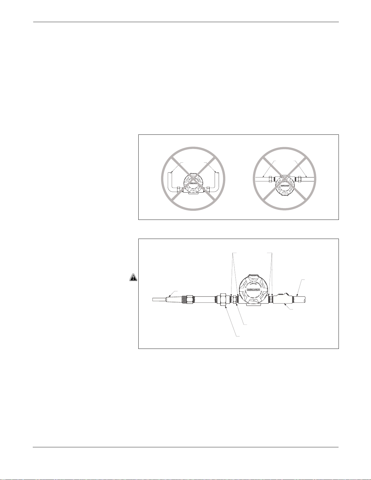
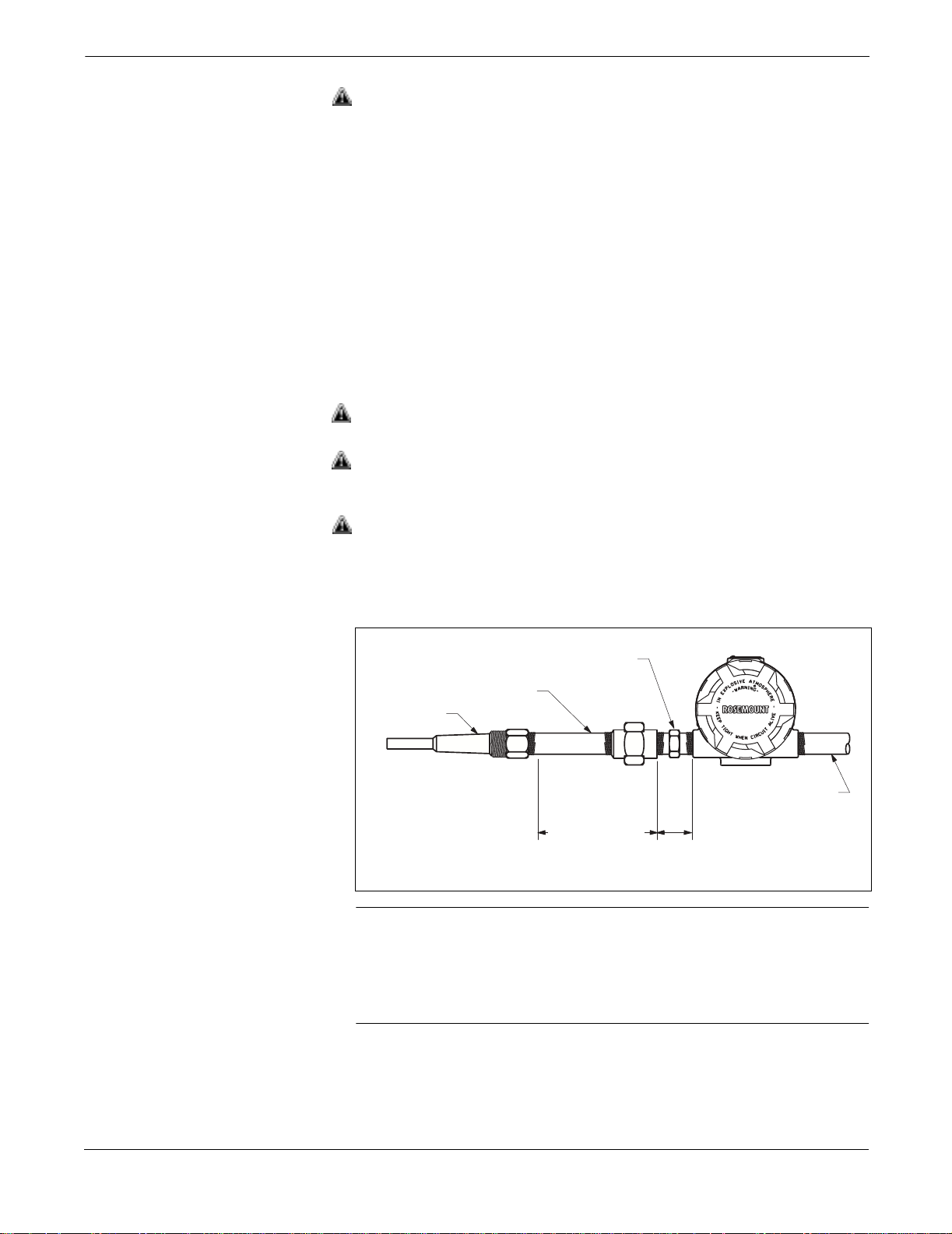
meet explosion-proof requirements.
3144-0429A, 0429B
3144-0430B
2-12
Installation
NOTE
Once a transmitter labeled with multiple approval types is installed, it
should not be reinstalled using any other labeled approval types. To
ensure this, the approval label should be permanently marked to
distinguish the used from the unused approval types.
INSTALLATION PROCEDURES
Figure 2- 11. Direct Mount and Remote
Mount Examples
Installation of the transmitter consists of mounting the transmitter, the
sensor, and making the electrical connections. You can mount the
transmitter directly to the sensor assembly or you can mount it
remotely (Figure 2-11). For a remote mount, use conduit or suitable
shielded cable with cable glands. The remainder of this section provides
the installation procedures for typical configuration in North America
and Europe.
Connection
Direct
Mount
Sensor
Assembly
Process Vessel
Sensor
Assembly
Head
Remote
Mount
Conduit or
Shielded Cable
3144-3144_04B
2-13
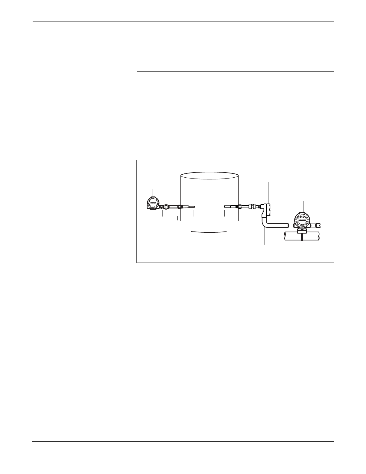
Rosemount Model 3244MV MultiVariable Temperature Transmitter with Foundation Fieldbus
Typical North American Configuration
1. Mount the thermowell to the pipe or process container wall. Be
sure to install and tighten thermowells and sensors. Perform a
leak check before applying pressure.
2. Attach any necessary unions (or couplings) and extension
fittings. Seal the fitting threads with silicone or tape (if required).
3. Screw the sensor into the thermowell.
4. Verify all sealing requirements for severe environments or to
satisfy code requirements.
5. Attach the transmitter to the thermowell assembly. Seal all
threads with silicone or tape (if required).
6. Pull sensor leads through the extensions and unions (or
couplings) into the terminal side of the transmitter housing.
7. Install conduit for field wiring to the remaining conduit entry of
the transmitter.
8. Pull the field wiring leads into the terminal side of the
transmitter housing. Avoid contact with leads and terminals.
9. Attach the sensor leads to the transmitter sensor terminals.
Attach the power leads to the transmitter power terminals. Avoid
contact with the leads and the terminals.
10. Attach and tighten both transmitter covers. Both transmitter
covers must be fully engaged to meet explosion-proof
requirements
Figure 2-12. Typical North American
Process M ounting Configuration
Sensor Hex
Union or Coupling
and Extension
Thermowell
Conduit for
3.2
Extension
Fitting
Length (E)
Note: Dimensionsare in inches (millimeters)
(81)
Field Wiring
(dc power)
NOTE
To prevent process fluid from entering the electrical conduit and
continuing to the control room, the National Electrical Code requires
that a barrier or seal be used in addition to the primary (sensor) seal.
Professional safety assistance is recommended for installations in
potentially hazardous processes.
Fieldbus-3244MV-0433B
2-14
Installation
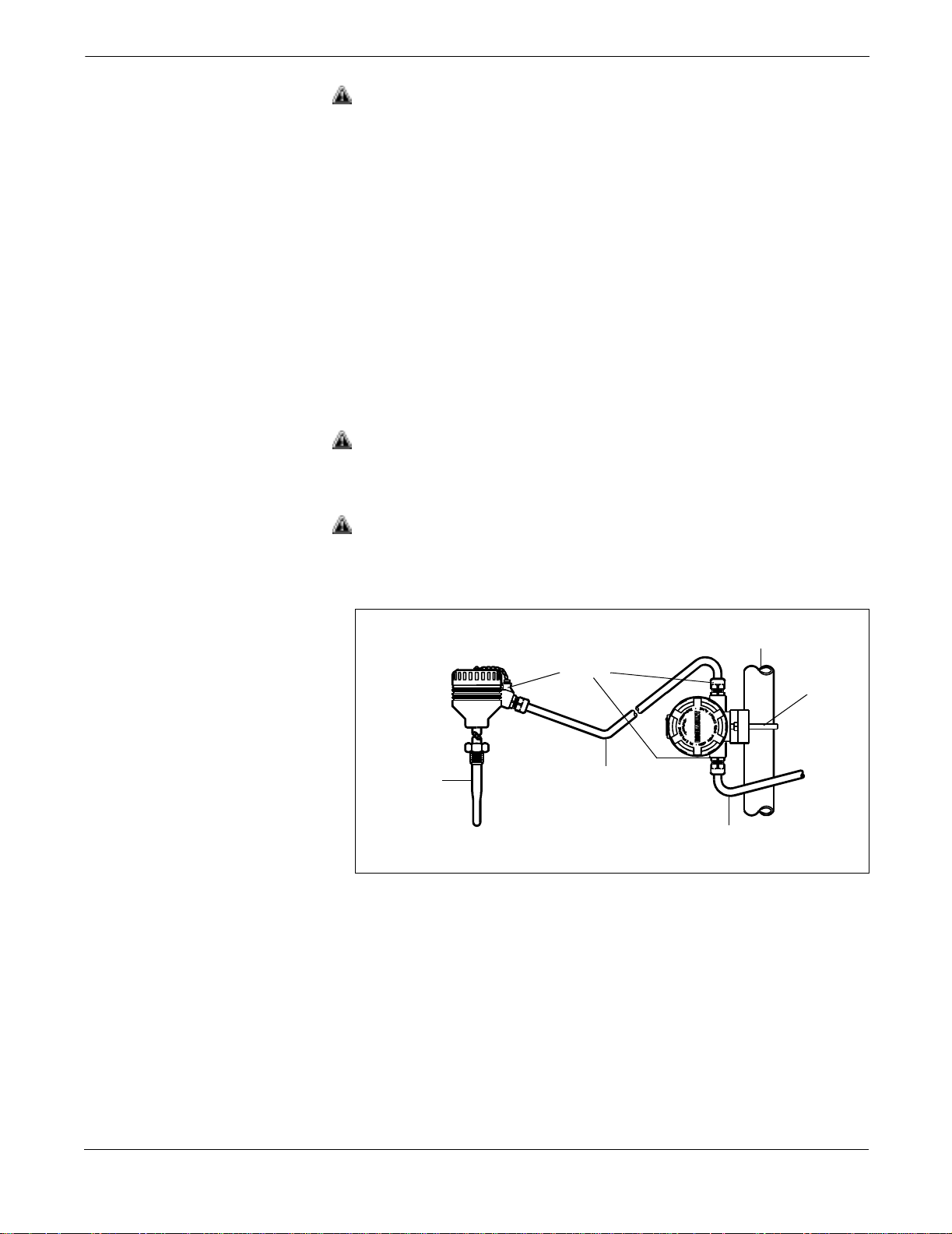
Typical European Configuration
1. Mount the thermowell to the pipe or the process container wall.
Install and tighten thermowells and sensors. Perform a leak
check before applying
process pressure.
2. Attach the connection head to the thermowell.
3. Insert the sensor into the thermowell and attach it to the
connection head.
4. Mount the transmitter to a 2-inch pipe or a suitable panel using
one of the optional mounting brackets (see Figure 2-7 on page
-10). The B4 mounting bracket is shown in Figure 2-13.
5. Attach cable glands to the shielded cable running from the
connection head to the transmitter and from the transmitter to
the control room.
6. Insert the shielded cable leads into the connection head and the
transmitter through the cable entries. Connect and tighten the
cable glands.
7. Connect the shielded cable leads to the sensor wiring leads inside
of the connection head, and the sensor wiring terminals inside
of the transmitter housing. Avoid contact with the leads and
the terminals.
8. Connect the shielded cable leads to the transmitter power
terminals. Avoid contact with the leads and the terminals.
Figure2-13. Typical European Process
Mounting Configuration
Sensor/
Thermowell
Cable
Glands
Shielded
Cable
fromSensor
2-Inch Pipe
Shielded Cable
from Transmitter
to Control Room
B4
Mounting
Bracket
644-0000B05b
2-15

Rosemount Model 3244MV MultiVariable Temperature Transmitter with Foundation Fieldbus
2-16
Loading...