


00809-0100-4140, Rev BA
Rosemount™ 2140 and 2140:SIS Level
Detectors
Vibrating Fork
Reference Manual
March 2022

Safety messages
NOTICE
Read this manual before working with the product. For personal and system safety, and for optimum product performance,
ensure you thoroughly understand the contents before installing, using, or maintaining this product.
For technical assistance, contacts are listed below:
Customer Central
Technical support, quoting, and order-related questions.
• United States - 1-800-999-9307 (7:00 am to 7:00 pm CST)
• Asia Pacific- 65 777 8211
North American Response Center
Equipment service needs.
• 1-800-654-7768 (24 hours a day — includes Canada)
• Outside of these areas, contact your local Emerson representative.
WARNING
Failure to follow safe installation and servicing guidelines could result in death or serious injury.
Ensure the level detector is installed by qualified personnel and in accordance with applicable code of practice.
Use the level detector only as specified in this manual. Failure to do so may impair the protection provided by the level detector.
The weight of a level detector with a heavy flange and extended fork length may exceed 37 lb. (18 kg). A risk assessment is
required before carrying, lifting, and installing the level detector.
For installations in hazardous locations, the level detector must be installed according to the Rosemount 2140 and 2140:SIS Level
Detectors Product Certifications document.
WARNING
Explosions could result in death or serious injury.
Verify that the operating atmosphere of the level detector is consistent with the appropriate hazardous locations certifications.
Before connecting a handheld communicator in an explosive atmosphere, ensure that the instruments in the loop are installed in
accordance with intrinsically safe or non-incendive field wiring practices.
In explosion-proof/flameproof and non-incendive installations, do not remove the housing covers when power is applied to the
level detector.
Both housing covers must be fully engaged to meet flameproof/explosion-proof requirements.
WARNING
Electrical shock could cause death or serious injury.
Avoid contact with the leads and terminals. High voltage that may be present on leads can cause electrical shock.
Ensure the power to the level detector is off, and the lines to any other external power source are disconnected or not powered
while wiring the level detector.
Ensure the wiring is suitable for the electrical current and the insulation is suitable for the voltage, temperature, and environment.
2

WARNING
Process leaks could result in death or serious injury.
Ensure the level detector is handled carefully. If the process seal is damaged, gas might escape from the vessel (tank) or pipe.
WARNING
Any substitution of non-recognized parts may jeopardize safety. Repair (e.g. substitution of components) may also
jeopardize safety and is not allowed under any circumstances.
Unauthorized changes to the product are strictly prohibited as they may unintentionally and unpredictably alter performance and
jeopardize safety. Unauthorized changes that interfere with the integrity of the welds or flanges, such as making additional
perforations, compromise product integrity and safety. Equipment ratings and certifications are no longer valid on any products
that have been damaged or modified without the prior written permission of Emerson. Any continued use of product that has
been damaged or modified without the written authorization is at the customer’s sole risk and expense.
WARNING
Physical access
Unauthorized personnel may potentially cause significant damage to and/or misconfiguration of end users’ equipment. This could
be intentional or unintentional and needs to be protected against.
Physical security is an important part of any security program and fundamental to protecting your system. Restrict physical access
by unauthorized personnel to protect end users’ assets. This is true for all systems used within the facility.
CAUTION
The products described in this document are NOT designed for nuclear-qualified applications.
Using non-nuclear qualified products in applications that require nuclear-qualified hardware or products may cause inaccurate
readings.
For information on Rosemount nuclear-qualified products, contact your local Emerson Sales Representative.
CAUTION
Hot surfaces
The flange and process seal may be hot at high process temperatures. Allow to cool before servicing.
3

4

Reference Manual Contents
00809-0100-4140 March 2022
Contents
Chapter 1 Introduction.............................................................................................................. 7
1.1 Using this manual........................................................................................................................ 7
1.2 NAMUR NE 53 revision.................................................................................................................8
1.3 Product certifications...................................................................................................................8
1.4 Product recycling/disposal...........................................................................................................8
Chapter 2 Level detector overview.............................................................................................9
2.1 Measurement principle................................................................................................................9
2.2 Process characteristics.................................................................................................................9
2.3 Vessel characteristics...................................................................................................................9
2.4 Application examples.................................................................................................................10
2.5 Components of the level detector..............................................................................................11
Chapter 3 Mechanical installation............................................................................................ 13
3.1 Safety messages........................................................................................................................ 13
3.2 Installation considerations.........................................................................................................14
3.3 Installation procedures.............................................................................................................. 22
3.4 Adjust display orientation (optional)..........................................................................................28
Chapter 4 Electrical installation................................................................................................29
4.1 Prepare the electrical connections............................................................................................. 29
4.2 Connect wiring and power up.................................................................................................... 32
Chapter 5 Configuration...........................................................................................................37
5.1 Safety messages........................................................................................................................ 37
5.2 Configuration tools....................................................................................................................38
5.3 Local Operator Interface (LOI)....................................................................................................39
5.4 Confirm correct device driver.....................................................................................................40
5.5 Confirm HART® revision capability............................................................................................. 40
Configure device using guided setup......................................................................................... 41
5.6
5.7 Verify the configuration.............................................................................................................41
5.8 Multidrop communication.........................................................................................................43
5.9 HART burst mode...................................................................................................................... 44
5.10 Security................................................................................................................................... 45
Chapter 6 Operation................................................................................................................ 49
6.1 LCD display screen messages.....................................................................................................49
6.2 Set up the LCD display............................................................................................................... 50
6.3 View measurement data............................................................................................................50
6.4 Check device status................................................................................................................... 51
6.5 Partial proof testing................................................................................................................... 53
Rosemount 2140 and 2140:SIS Level Detectors 5

Contents Reference Manual
March 2022 00809-0100-4140
Chapter 7 Service and troubleshooting.................................................................................... 57
7.1 Safety messages........................................................................................................................ 57
7.2 Diagnostic messages................................................................................................................. 58
7.3 Troubleshooting the 4-20 mA/HART Output..............................................................................68
7.4 Service and troubleshooting tools..............................................................................................69
7.5 Opening the lid (cover).............................................................................................................. 76
7.6 Service support..........................................................................................................................76
Appendix A Specifications and reference data............................................................................. 79
A.1 General......................................................................................................................................79
A.2 Functional safety....................................................................................................................... 79
A.3 Performance specifications........................................................................................................79
A.4 Electrical specifications..............................................................................................................80
A.5 Environmental specifications.....................................................................................................81
A.6 Physical specifications............................................................................................................... 83
A.7 Dimensional drawings............................................................................................................... 84
Appendix B Configuration parameters........................................................................................ 93
B.1 Manual setup.............................................................................................................................93
B.2 Alert setup...............................................................................................................................104
Appendix C Local Operator Interface (LOI) menu trees.............................................................. 109
C.1 LOI menu trees........................................................................................................................ 109
Appendix D Signal processing................................................................................................... 111
6 Reference Manual

Reference Manual Introduction
00809-0100-4140 March 2022
1 Introduction
1.1 Using this manual
The sections in this manual provide detailed information on installing, operating, and
maintaining the Rosemount 2140 and 2140:SIS Level Detectors.
The sections are organized as follows:
Level detector overview provides a description of the Rosemount 2140 and , and their
basic principles.
Mechanical installation contains mechanical installation instructions.
Electrical installation contains electrical installation instructions.
Configuration provides instructions on configuration of the level detector.
Operation contains operation and maintenance techniques.
Service and troubleshooting provides troubleshooting techniques for the most common
operating problems.
Specifications and reference data contains specifications and dimensional drawings.
Configuration parameters provides extended information about the configuration
parameters.
Local Operator Interface (LOI) menu trees contains complete menu maps as a reference
for when using the optional Local Operator Interface.
Signal processing contains a schematic overview of the signal processing.
Rosemount 2140 and 2140:SIS Level Detectors 7

Introduction Reference Manual
March 2022 00809-0100-4140
1.2 NAMUR NE 53 revision
The Rosemount 2140 meets the NAMUR recommendation NE 53. Table 1-1 provides the
information necessary to ensure you have the correct device driver for your device.
Table 1-1: Identification and Compatibility According to NAMUR NE 53
Release date Device identification FDI, DD, and DTM identification Release note
NAMUR
hardware
revision
January-2017 1.0.0 1.0.0 5 1 • Initial release
March-2018 1.0.0 1.1.0 5 1 • Removed customer upgrade
(1)
NAMUR
software
revision
HART® universal
(1)
revision
(2)
7 2
7 2
Device revision
(revision level 1 and 2)
feature
• Added Media Learn and
Remote Proof Test to base
model
• Updated the Partial Proof Test
procedure
(1)
(1) NAMUR Revision is located on the device label. Differences in level 3 changes represent minor product changes as
defined per NE53. Compatibility and functionality are preserved and product can be used interchangeably.
(2) HART Revision 5 and 7 can be switched in field.
Related information
Confirm correct device driver
1.3 Product certifications
See the Rosemount 2140 Product Certifications document for detailed information on the
existing approvals and certifications.
1.4 Product recycling/disposal
Recycling of equipment and packaging should be taken into consideration and disposed of
in accordance with local and national legislation or regulations.
8 Reference Manual

Reference Manual Level detector overview
00809-0100-4140 March 2022
2 Level detector overview
2.1 Measurement principle
The Rosemount 2140 and 2140:SIS are the world’s first wired HART® level detector using
Emerson's vibrating fork technology.
Using the principle of a tuning fork, a piezo-electric crystal oscillates the forks at their
natural frequency. Changes to the oscillation frequency are continuously monitored by
electronics as it varies depending on the liquid medium in which the forks are immersed.
The denser the liquid, the lower the oscillation frequency.
Whenever a liquid medium in a vessel (tank) or pipe drains down past the forks, it causes a
distinct frequency change. This change is detected by the electronics and a dry condition
is indicated.
Whenever a liquid medium in a vessel (tank) or pipe rises and contacts the forks, again a
distinct frequency change is detected. This time, the electronics will indicate a wet
condition.
The wet and dry conditions can be transmitted digitally as a HART signal or as a discrete
output using the analog output.
Related information
Analog output
Signal processing
2.2 Process characteristics
Emerson's vibrating fork technology is virtually unaffected by turbulence, foam, solids
content, coating products, and liquid properties. The natural frequency (1400 Hz) of the
fork avoids interference from plant vibration that may cause false detection. This allows
for minimum intrusion into the tank or pipe using a short fork.
2.2.1 Liquid-to-sediment detection
The Rosemount 2140 version of the level detector features settings to detect liquid-tosediment interface, and this works on other solids sediment types (e.g. salts). Liquids as
well as wet sediments are detected. All versions of the level detector have a Media Learn
function to fine-tune the switching point even if the media characteristics are unknown.
2.3 Vessel characteristics
The level detector should be mounted using its process connection, and in a horizontal or
vertical orientation so that the liquid medium can flow freely in the gap between the forks.
A vessel (tank) or pipe can be almost any shape or type, but check that the process
conditions are within the operating limits of the level detector.
Rosemount 2140 and 2140:SIS Level Detectors 9

Level detector overview Reference Manual
March 2022 00809-0100-4140
Avoid installing near agitators and inlet pipes where the forks are likely to be splashed and
cause a false detection of a wet condition. False detection events can be minimized by a
programmable delay that allows time for the fork to dry.
Never force the level detector into a vessel (tank) or pipe space. Any contact with the
opposite wall, or in-tank objects, could damage the forks and other wetted-process parts.
Extended length versions require supports at regular spaced intervals.
2.4 Application examples
Applications for the Rosemount 2140 version of the level detector include overfill
prevention (Figure 2-1), high and low level alarms, pump protection, and separation
processes (Figure 2-2).
The Rosemount 2140:SIS version is certified to IEC 61508 for safety-critical applications.
Applications also include overfill prevention, high and low level alarms, and pump
protection.
Figure 2-1: Overfill Prevention
Figure 2-2: High and Low level Alarms and Pump Control
10 Reference Manual

A
B
C
E
F
J
HH
D
A
K
G
Reference Manual Level detector overview
00809-0100-4140 March 2022
2.5 Components of the level detector
Figure 2-3 shows the components of a Rosemount 2140.
Figure 2-3: Rosemount 2140 Features
A. Terminal compartment
B. Electronics housing
C.
LOI display (optional)
D. ‘Fast drip’ forks
E. Threaded process connection (BSPT (R) or BSPP (G))
F. Tri Clamp process connection
G. Flanged process connection
H. Two cable/conduit entries (½-14 ANPT or M20 x 1.5)
I. External ground screw
J. Thermal tube (on high temperature version only)
2.5.1 Short fork technology
Using short-fork technology, the device can be used in almost all liquid applications.
Extensive research has maximized the operational effectiveness of the fork design, making
it suitable for most liquid mediums including coating liquids, aerated liquids, and slurries.
Rosemount 2140 and 2140:SIS Level Detectors 11
Level detector overview Reference Manual
March 2022 00809-0100-4140
2.5.2 Fork design
The “fast drip” design allows the liquid to be quickly drawn away from the fork tip, making
the Rosemount 2140 quicker and more responsive in high density or viscous liquid
applications.
Figure 2-4: “Fast drip” forks
12 Reference Manual

Reference Manual Mechanical installation
00809-0100-4140 March 2022
3 Mechanical installation
3.1 Safety messages
Instructions and procedures in this section may require special precautions to ensure the
safety of the personnel performing the operations. Information that potentially raises
safety issues is indicated by a warning symbol ( ). Refer to the following safety messages
before performing an operation preceded by this symbol.
WARNING
Failure to follow safe installation and servicing guidelines could result in death or
serious injury.
Ensure the level detector is installed by qualified personnel and in accordance with
applicable code of practice.
Use the level detector only as specified in this manual. Failure to do so may impair the
protection provided by the level detector.
The weight of a level detector with a heavy flange and extended fork length may exceed
37 lb. (18 kg). A risk assessment is required before carrying, lifting, and installing the level
detector.
For installations in hazardous locations, the level detector must be installed according to
the Rosemount 2140 and 2140:SIS Level Detectors Product Certifications document.
Repair, e.g. substitution of components, etc. may jeopardize safety and is under no
circumstances allowed.
WARNING
Explosions could result in death or serious injury.
Verify that the operating atmosphere of the level detector is consistent with the
appropriate hazardous locations certifications.
Before connecting a handheld communicator in an explosive atmosphere, ensure that the
instruments in the loop are installed in accordance with intrinsically safe or non-incendive
field wiring practices.
In explosion-proof/flameproof and non-incendive installations, do not remove the housing
covers when power is applied to the level detector.
Both housing covers must be fully engaged to meet flameproof/explosion-proof
requirements.
Rosemount 2140 and 2140:SIS Level Detectors 13
Mechanical installation Reference Manual
March 2022 00809-0100-4140
WARNING
Electrical shock could cause death or serious injury.
Avoid contact with the leads and terminals. High voltage that may be present on leads can
cause electrical shock.
Ensure the power to the level detector is off, and the lines to any other external power
source are disconnected or not powered while wiring the level detector.
Ensure the wiring is suitable for the electrical current and the insulation is suitable for the
voltage, temperature, and environment.
WARNING
Process leaks could result in death or serious injury.
Ensure the level detector is handled carefully. If the process seal is damaged, gas might
escape from the vessel (tank) or pipe.
WARNING
Physical access
Unauthorized personnel may potentially cause significant damage to and/or
misconfiguration of end users’ equipment. This could be intentional or unintentional and
needs to be protected against.
Physical security is an important part of any security program and fundamental to
protecting your system. Restrict physical access by unauthorized personnel to protect end
users’ assets. This is true for all systems used within the facility.
CAUTION
Hot surfaces
The flange and process seal may be hot at high process temperatures. Allow to cool before
servicing.
3.2 Installation considerations
Before installing the level detector, review the safety, environmental, application, and preinstallation sections.
3.2.1 Environmental considerations
The Rosemount 2140 is weatherproof and protected against the ingress of dust, but must
be protected from flooding. Avoid installing the level detector near heat sources.
14 Reference Manual

OKOK
Reference Manual Mechanical installation
00809-0100-4140 March 2022
Figure 3-1: Environmental Considerations
3.2.2 Application considerations
The level detectors can be mounted in an open or closed tank, or a pipe. There is a wide
range of threaded, flanged, and hygienic process connection options.
For most liquids, including coating, aerated liquids and slurries, the function is virtually
unaffected by flow, turbulence, bubbles, foam, vibration, solid particles, build-up, or
properties of the liquid medium.
Avoid process medium build-up on the forks
Avoid situations where a drying and coating process medium may create an excessive
build-up or implement preventative maintenance programs to ensure the build-up is not
enough to impair performance (see Figure 3-2).
Rosemount 2140 and 2140:SIS Level Detectors 15

OK
Mechanical installation Reference Manual
March 2022 00809-0100-4140
Always ensure:
• There is sufficient distance between build-up on the tank wall and the fork.
• There is no risk of ‘bridging’ the level switch forks.
Examples of products that can create ‘bridging’ of forks and impair performance are
dense paper slurries and bitumen.
Figure 3-2: Avoid Product Build-up
Operating temperature and pressure ranges
Ensure the process is operating within the instrument operating temperature and pressure
ranges.
Liquid density requirements
Minimum liquid density is 0.4 SG (400 kg/m3).
Liquid viscosity range
Up to 10000 cP (centiPoise) when operating in the Normal mode.
Up to 1000 cP (centiPoise) when operating in Enhanced mode.
Foams
In almost all cases, the Rosemount 2140 is insensitive to foams (i.e. does not see the
foam).
However in rare occasions, some very dense foams may be seen as liquid; known examples
of this are found in ice-cream and orange juice manufacturing.
16 Reference Manual

SP
HYSP
0.5
(13)
0.1
(2.5)
0.5
(13)
Reference Manual Mechanical installation
00809-0100-4140 March 2022
Switching point
The switching point varies with different liquid densities. The switching point (SP) and
hysteresis (HY) for water are shown in Figure 3-3.
Figure 3-3: Switching Point in Inches (Millimeters)
Note
When mounted vertically, a low density medium has a switching point closer to the
process connection. A high density medium has a switching point closer to fork tip.
3.2.3 Pre-installation considerations
Measurement accuracy is dependent upon the proper installation of the device. Keep in
mind the need for easy access, personnel safety, practical field calibration, and a suitable
environment for the device.
Device identification
To identify a version of the level detector, see the label on the housing.
How to handle a level detector
Handle the level detector with great care.
The weight of the level detector with a heavy flange and extended fork length may exceed
37 lb. (18 kg). A risk assessment is required to be done before carrying, lifting, and
installing the level detector.
Use both hands to carry the extended length and high temperature versions, and do not
hold a level detector by the forks (see Figure 3-4).
Rosemount 2140 and 2140:SIS Level Detectors 17

Mechanical installation Reference Manual
March 2022 00809-0100-4140
Figure 3-4: Handling
Make no alterations to the level detector
Never make any alterations to the mechanical or electrical features of the level detector
(see Figure 3-5).
Figure 3-5: Make No Alterations
Allow adequate space outside tank or pipe
Mount a level detector so that it is removable and allow both covers to be removed.
Ensure there is also enough room for fitting cable glands and cables.
Clearances:
• A clearance of 0.75 in. (19 mm) is required for the standard covers to be removed.
• If an LCD display is installed, provide 3 in. (76.2 mm) of clearance for the extended
cover to be removed.
Note
The electronics housing can be rotated for optimal viewing position of an LCD display (if
fitted) and to assist with the cabling.
18 Reference Manual

D
A
B
Reference Manual Mechanical installation
00809-0100-4140 March 2022
Covers installation
Ensure a proper seal by installing the electronics housing covers so that metal contacts
metal. Always use Emerson's O-rings.
Mounting orientation
Mount the Rosemount 2140 at any angle that allows the level of the process medium to
rise, fall, or flow through the fork gap.
Related information
Correct fork alignment
Pipe installation requirements
• The inside pipe diameter (D) must be 1.4 in. (35 mm) or larger.
• Ensure the fork tines intrude at least 0.9 in. (22 mm) into the pipe.
• Keep at least 0.3 in. (7 mm) of clearance between the fork tines and the pipe wall.
Figure 3-6: Pipe Installation
A. Minimum intrusion 0.9 in. (22 mm)
B. Minimum clearance 0.3 in. (7 mm)
Rosemount 2140 and 2140:SIS Level Detectors 19

B
B
A
Mechanical installation Reference Manual
March 2022 00809-0100-4140
Other recommendations
• Avoid:
— Installing near to liquid entering the tank at the filling-point.
— Heavy splashing on the forks.
Increasing the sensor output delay reduces accidental detection caused by splashing.
• Always ensure:
— The overall system is tested during commissioning.
— The installation does not create tank crevices around the forks where a liquid
medium may collect. This event can happen with high-viscosity and high-density
liquids.
— The forks do not come into contact with the vessel (tank) or pipe wall, internal
fittings, or any other obstructions.
• Extra consideration is needed if the plant vibration is close to the 1400 Hz operating
frequency of the fork.
Required supports for extended fork
Supporting the extended fork avoids long fork length vibration.
Figure 3-7: Vertical Installation
20 Reference Manual
B. 3.28 ft. (1.0 m)
A. Maximum 3.28 ft. (1.0 m)

A
B B
Reference Manual Mechanical installation
00809-0100-4140 March 2022
Figure 3-8: Horizontal Installation
A. Maximum 3.28 ft. (1.0 m)
3.28 ft. (1.0 m)
B.
Rosemount 2140 and 2140:SIS Level Detectors 21

B
A
C
D
E
F
Mechanical installation Reference Manual
March 2022 00809-0100-4140
3.3 Installation procedures
3.3.1 Process connection seals
Figure 3-9: Process Connection Seals
A. PTFE tape
B. NPT or BSPT (R) thread
C. Gasket
D. BSPP (G) thread
22 Reference Manual
E. Tri Clamp
F. The Tri Clamp seal is supplied in an accessory kit

OKOK
OK
C
A
B
OK
A
B
OK
A
B
Reference Manual Mechanical installation
00809-0100-4140 March 2022
3.3.2 Correct fork alignment
Fork alignment in a vessel (tank) installation
The fork is correctly aligned by positioning the groove or notch as indicated (Figure 3-10).
Figure 3-10: Correct Fork Alignment for Vessel (Tank) Installation
A. Tri Clamp process connections have a circular notch
B. Threaded process connections have a groove
C.
Flanged process connections have a circular notch
Fork alignment in a pipe installation
The fork is correctly aligned by positioning the groove or notch as indicated (Figure 3-11).
Figure 3-11: Correct Fork Alignment for Pipe Installation
A. Tri Clamp process connections have a circular notch
B. Threaded process connections have a groove
Rosemount 2140 and 2140:SIS Level Detectors 23

A
A
Mechanical installation Reference Manual
March 2022 00809-0100-4140
3.3.3 Mounting the threaded version
Threaded vessel (tank) or pipework connection
Procedure
1. Seal and protect the threads. Use anti-seize paste or PTFE tape according to site
procedures.
A gasket may be used as a sealant for BSPP (G) threaded connections.
2. Screw the level detector into the process connection.
Note
Tighten using the hexagon nut only.
Figure 3-12: Vertical Installation
A. Gasket for BSPP (G) threaded connection
Figure 3-13: Horizontal Installation
A. Gasket for BSPP (G) threaded connection
24 Reference Manual

A
Reference Manual Mechanical installation
00809-0100-4140 March 2022
Threaded flange connection
Procedure
1. Place the customer-supplied flange and gasket on the vessel (tank) nozzle.
A. Gasket (customer supplied)
2. Tighten the bolts and nuts with sufficient torque for the flange and gasket.
3. Seal and protect the threads. Use anti-seize paste or PTFE tape according to site
procedures.
A gasket may be used as a sealant for BSPP (G) threaded connections.
Rosemount 2140 and 2140:SIS Level Detectors 25

A
A
Mechanical installation Reference Manual
March 2022 00809-0100-4140
4. Screw the level detector into the flange thread.
Note
Tighten using the hexagon nut only.
A. Gasket for BSPP (G) threaded connection
3.3.4 Mounting the flanged version
Procedure
1. Lower the level detector into the nozzle.
A. Gasket (customer supplied)
26 Reference Manual

A
Reference Manual Mechanical installation
00809-0100-4140 March 2022
2. Tighten the bolts and nuts with sufficient torque for the flange and gasket.
3.3.5 Mounting the Tri Clamp version
Procedure
1. Lower the level detector into the flange face.
A. Seal (supplied with Tri Clamp)
Rosemount 2140 and 2140:SIS Level Detectors 27
H3/32 in.
Torque 30 in-lb (3 Nm)
Mechanical installation Reference Manual
March 2022 00809-0100-4140
2. Fit the Tri Clamp.
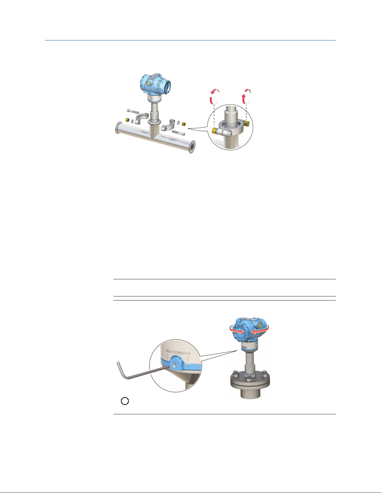
3.4 Adjust display orientation (optional)
To improve field access to wiring or to better view the optional LCD display:
Procedure
1. Loosen the set screw until the level detector housing can rotate smoothly.
Do not unscrew all the way. Rotating the housing, without this screw in place, can
damage the internal wiring.
2.
First, rotate the housing clockwise to the desired location.
If the desired location cannot be achieved due to thread limit, rotate the housing
counterclockwise.
3. Re-tighten the set screw.
Note
Do not attempt to rotate the display beyond the thread limits.
Figure 3-14: Housing Rotation
28 Reference Manual

Reference Manual Electrical installation
00809-0100-4140 March 2022
4 Electrical installation
4.1 Prepare the electrical connections
4.1.1 Cable selection
Use 24–14 AWG wiring. Twisted-pairs and shielded wiring is recommended for
environments with high EMI (electromagnetic interference). Two wires can be safely
connected to each terminal screw.
4.1.2 Cable glands/conduits
For intrinsically safe, explosion-proof/flameproof, and dust-proof installations, only use
certified cable glands or conduit entry devices. Ordinary location installations can use
suitably rated cable glands or conduit entry devices to maintain the Ingress Protection (IP)
rating.
Unused conduit entries must always be sealed with a suitably rated blanking/stopping
plug.
Note
Do not run signal wiring in conduit or open trays with power wiring or near heavy electrical
equipment.
4.1.3 Power supply
Each level detector operates on 10.5 – 42.4 Vdc (10.5 – 30 Vdc in Intrinsically Safe
installations) at the level detector terminals.
4.1.4 Power consumption
Maximum of 1 W, and current maximum is 23 mA.
4.1.5 Hazardous areas
When the device is installed in hazardous areas (classified locations), local regulations and
the conditions-of-use specified in applicable certificates must be observed. Review the
Rosemount 2140 Product Certifications document for information.
4.1.6 Load limitations
For HART® communications, a minimum load resistance of 250 Ω is required.
The maximum loop resistance is determined by the voltage level of the external power
supply (see Figure 4-1).
Rosemount 2140 and 2140:SIS Level Detectors 29

1400
1200
1000
800
600
400
200
0
100 20 30 40 50
250
587
848
1392
16.3 24 42.4
10.5
A
B
-
+
-
+
Fn
1
2
3
4
5
6
7
8
9
0
-
.
A
C
D
E
FB
Electrical installation Reference Manual
March 2022 00809-0100-4140
Figure 4-1: Load Limitations
Maximum loop resistance = 43.5 × (external power supply voltage - 10.5)
A. Loop resistance in Ohms (Ω)
B.
External power supply voltage (Vdc)
4.1.7 Wiring diagram
Figure 4-2: 4-20 mA/HART® Communication
A. Handheld communicator
B. Approved IS barrier (for Intrinsically Safe installations only)
HART modem
C.
D. Load resistance (≥250 Ω)
E. Current meter
F. Power supply
30 Reference Manual
 Loading...