

Manual: Rosemount 2051 with Selectable HART with 4-20 mA HART (Revision 5 and 7) protocols
Table of contents
 Loading...
Rosemount Manual: Rosemount 2051 with Selectable HART with 4-20 mA HART (Revision 5 and 7) protocols Manuals & Guides
Reference Manual
00809-0100-4107, Rev CB
Rosemount™ 2051 Pressure Transmitter
with HART® Revision 5 and 7 Selectable Protocol
September 2020

Safety messages
NOTICE
Read this manual before working with the product. For personal and system safety, and for optimum product
performance, make sure you thoroughly understand the contents before installing, using, or maintaining this product.
See listed technical assistance contacts.
Customer Central
Technical support, quoting, and order-related questions.
United States - 1-800-999-9307 (7:00 am to 7:00 pm CST)
Asia Pacific- 65 777 211
Europe/ Middle East/Africa - 49 (8153) 9390
North American Response Center
Equipment service needs.
1-800-654-7768 (24 hours—includes Canada)
Outside of these areas, contact your local Emerson representative.
CAUTION
The products described in this document are NOT designed for nuclear-qualified applications.
Using non-nuclear qualified products in applications that require nuclear-qualified hardware or products may cause inaccurate
readings.
For information on Rosemount nuclear-qualified products, contact your local Emerson Sales Representative.
WARNING
Explosions can result in death or serious injury.
Do not remove the transmitter covers in explosive environments when the circuit is live.
Fully engage both transmitter covers to meet explosion-proof requirements.
Before connecting a communicator in an explosive atmosphere, make sure the instruments in the loop are installed in accordance
with intrinsically safe or non-incendive field wiring practices.
Verify the operating atmosphere of the transmitter is consistent with the appropriate hazardous locations certifications.
Electrical shock could cause death or serious injury.
Avoid contact with the leads and terminals.
Process leaks could result in death or serious injury.
Install and tighten all four flange bolts before applying pressure.
Do not attempt to loosen or remove flange bolts while the transmitter is in service.
Replacement equipment or spare parts not approved by Emerson or use as spare parts could reduce the pressure retaining
capabilities of the transmitter and may render the instrument dangerous.
Use only bolts supplied or sold by Emerson as spare parts.
Improper assembly of manifolds to traditional flange can damage SuperModule™ Platform.
For safe assembly of manifold to traditional flange, bolts must break back plane of flange web (i.e., bolt hole) but must not contact
sensor module housing.
2

WARNING
SuperModule and electronics housing must have equivalent approval labeling in order to maintain hazardous location
approvals.
When upgrading, verify SuperModule and electronics housing certifications are equivalent. Differences in temperature class
ratings may exist, in which case the complete assembly takes the lowest of the individual component temperature classes (for
example, a T4/T5 rated electronics housing assembled to a T4 rated SuperModule is a T4 rated transmitter.)
Severe changes in the electrical loop may inhibit HART® Communication or the ability to reach alarm values. Therefore, Emerson
cannot absolutely warrant or guarantee that the correct failure alarm level (HIGH or LOW) can be read by the host system at the
time of annunciation.
Physical access
Unauthorized personnel may potentially cause significant damage to and/or misconfiguration of end users’ equipment. This could
be intentional or unintentional and needs to be protected against.
Physical security is an important part of any security program and fundamental to protecting your system. Restrict physical access
by unauthorized personnel to protect end users’ assets. This is true for all systems used within the facility.
3

4

Reference Manual Contents
00809-0100-4107 September 2020
Contents
Chapter 1 Introduction.............................................................................................................. 7
1.1 Using this manual........................................................................................................................ 7
1.2 Models covered........................................................................................................................... 7
1.3 HART installation flowchart..........................................................................................................8
1.4 Transmitter overview...................................................................................................................9
1.5 Product recycling/disposal.........................................................................................................10
Chapter 2 Configuration...........................................................................................................11
2.1 Overview................................................................................................................................... 11
2.2 Safety messages........................................................................................................................ 11
2.3 System readiness.......................................................................................................................12
2.4 Configuration basics.................................................................................................................. 13
2.5 Verify configuration...................................................................................................................16
2.6 Basic setup of the transmitter.................................................................................................... 18
2.7 Configuring the LCD display.......................................................................................................24
2.8 Detailed transmitter setup.........................................................................................................25
2.9 Performing transmitter tests......................................................................................................31
2.10 Configuring burst mode...........................................................................................................33
2.11 Establishing multidrop communication................................................................................... 34
Chapter 3 Hardware Installation.............................................................................................. 37
3.1 Overview................................................................................................................................... 37
3.2 Safety messages........................................................................................................................ 37
3.3 Considerations...........................................................................................................................38
3.4 Installation procedures.............................................................................................................. 39
3.5 Rosemount 305, 306, and 304 Manifolds...................................................................................49
3.6 Liquid level measurement..........................................................................................................60
Chapter 4 Electrical Installation................................................................................................65
4.1 Overview................................................................................................................................... 65
4.2 Safety messages........................................................................................................................ 65
4.3 LOI/LCD display .........................................................................................................................66
4.4 Configure security and simulation..............................................................................................67
4.5 Setting transmitter alarm.......................................................................................................... 70
4.6 Electrical considerations............................................................................................................ 70
Chapter 5 Operation and Maintenance.....................................................................................79
5.1 Overview................................................................................................................................... 79
5.2 Safety messages........................................................................................................................ 79
5.3 Recommended calibration tasks................................................................................................80
Reference Manual 5

Contents Reference Manual
September 2020 00809-0100-4107
5.4 Calibration overview..................................................................................................................81
5.5 Determining calibration frequency............................................................................................ 83
5.6 Compensating for span line pressure effects (range 4 and 5)..................................................... 85
5.7 Trim the pressure signal.............................................................................................................86
5.8 Trim the analog output..............................................................................................................89
5.9 Switching HART revision............................................................................................................ 92
Chapter 6 Troubleshooting...................................................................................................... 95
6.1 Overview................................................................................................................................... 95
6.2 Safety messages........................................................................................................................ 95
6.3 Service support..........................................................................................................................96
6.4 Troubleshooting tables..............................................................................................................97
6.5 Diagnostic messages................................................................................................................. 99
6.6 Disassembly procedures.......................................................................................................... 102
6.7 Reassembly procedures...........................................................................................................104
Chapter 7 Safety Instrumented Systems Requirements.......................................................... 107
7.1 Safety certified identification...................................................................................................107
7.2 Installation in SIS applications..................................................................................................107
7.3 Configuring in SIS applications.................................................................................................108
7.4 SIS operation and maintenance............................................................................................... 109
7.5 Inspection................................................................................................................................110
Appendix A Reference data....................................................................................................... 113
A.1 Product certifications.............................................................................................................. 113
A.2 Ordering information, specifications, and drawings.................................................................113
Appendix B Field Communicator Menu Trees and Fast Keys.......................................................115
B.1 Field Communicator menu trees..............................................................................................115
B.2 Field communicator Fast Keys..................................................................................................119
Appendix C Local Operator Interface (LOI) Menu....................................................................... 121
C.1 LOI menu tree..........................................................................................................................121
C.2 LOI menu tree - extended menu.............................................................................................. 122
C.3 Number entry..........................................................................................................................123
C.4 Text entry................................................................................................................................124
6 Rosemount 2051 Pressure Transmitter

Reference Manual
00809-0100-4107 September 2020
Introduction
1 Introduction
1.1 Using this manual
The sections in this manual provides information on configuring, troubleshooting,
operating, and maintaining the Rosemount 2051 Pressure Transmitter specifically with
HART® Revision 5 and 7 Selectable Protocol.
The sections in this manual are organized as follows:
• Configuration provides instruction on configuration of the tranmitter, information on
software functions, configuration parameters, and other variables are also included.
• Hardware Installation contains mechanical installation instructions, and field upgrade
options.
• Electrical Installation contains electrical installation instructions, and field upgrade
options.
• Operation and Maintenance provides detailed information on calibrating and changing
HART® Revisions.
• Troubleshooting provides troubleshooting techniques for the most common operating
problems.
• Safety Instrumented Systems Requirements provides identification, installation,
configuration, operation and maintenance, and inspection information for Safety
Instrumented Systems.
• Reference data supplies links to updated specifications, ordering information, intrinsic
safety approval information, European ATEX directive information, and approval
drawings.
• Field Communicator Menu Trees and Fast Keys provides full menu trees and
abbreviated Fast Key sequences for commisioning tasks.
• Local Operator Interface (LOI) Menu provides detailed LOI menu trees.
1.2 Models covered
The following 2051 Transmitters are covered by this manual:
• Rosemount 2051C Coplanar™ Pressure Transmitter
— Measures differential and gauge pressure up to 2000 psi (137.9 bar).
• Rosemount 2051T In-Line Pressure Transmitter
— Measures gauge/absolute pressure up to 10000 psi (689.5 bar).
• Rosemount 2051L Level Transmitter
— Measures level and specific gravity up to 300 psi (20.7 bar).
• Rosemount 2051CF Series Flowmeter
— Measures flow in line sizes from -in. (15mm) to 96-in. (2400 mm).
Reference Manual 7
Introduction Reference Manual
September 2020 00809-0100-4107
Note
For Rosemount 2051 with FOUNDATION Fieldbus, see Reference Manual. For Rosemount
2051 with PROFIBUS PA Protocol, see Reference Manual.
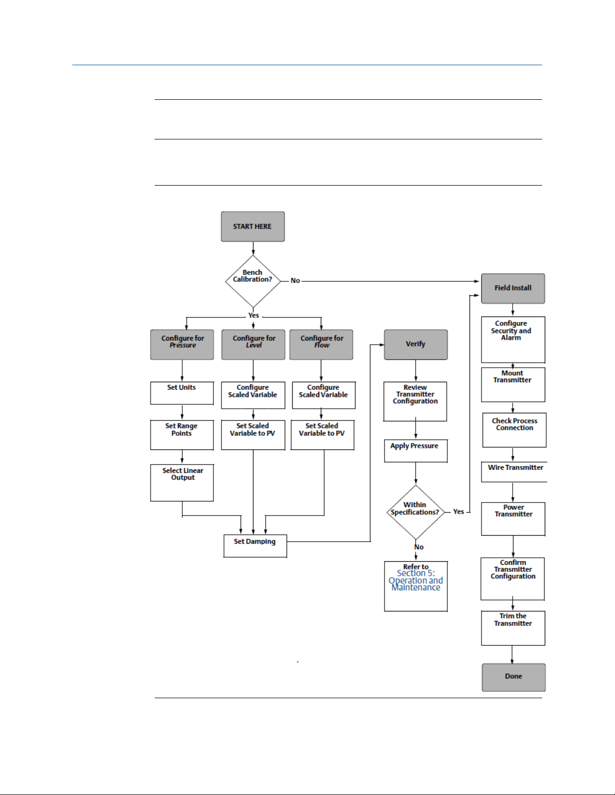
1.3 HART installation flowchart
Figure 1-1: HART Installation Flowchart
8 Rosemount 2051 Pressure Transmitter

Reference Manual Introduction
00809-0100-4107 September 2020
1.4 Transmitter overview
The Rosemount 2051C Coplanar™ design is offered for Differential Pressure (DP) and
Gauge Pressure (GP) measurements. The Rosemount 2051C utilizes capacitance sensor
technology for DP and GP measurements. The Rosemount 2051T utilizes piezoresistive
sensor technology for AP and GP measurements.
The major components of the transmitter are the sensor module and the electronics
housing. The sensor module contains the oil filled sensor system (isolating diaphragm, oil
fill system, and sensor) and the sensor electronics. The sensor electronics are installed
within the sensor module and include a temperature sensor, a memory module, and the
analog-to-digital signal converter (A/D converter). The electrical signals from the sensor
module are transmitted to the output electronics in the electronics housing. The
electronics housing contains the output electronics board, the optional external
configuration buttons, and the terminal block. The basic block diagram of the transmitter
is illustrated in Figure 1-3.
When pressure is applied to the isolating diaphragm, the oil deflects the sensor which then
changes its capacitance or voltage signal. This signal is then changed to a digital signal by
the Signal Processing. The microprocessor then takes the signals from the Signal
Processing and calculates the correct output of the transmitter. This signal is then sent to
the D/A converter, which converts the signal back to the analog signal, then superimposes
the HART® signal on the 4–20 mA output.
An optional LCD display can be ordered that connects directly to the interface board which
maintains direct access to the signal terminals. The display indicates output and
abbreviated diagnostic messages. A glass display cover is provided. For 4-20 mA HART
output, the LCD display features a two-line display. The first line displays the actual
measured value, the second line of six characters displays the engineering units. The LCD
display can also display diagnostic messages.
Note
LCD display utilizes a 5 × 6 character display and can display output and diagnostic
messages. The LOI display uses an 8 × 6 character display and can display output,
diagnostic messages, and LOI menu screens. The LOI display comes with two buttons
mounted on the front of the display board. See Figure 1-2.
Figure 1-2: LCD/LOI display
LCD display
LOI display
Reference Manual 9

Introduction Reference Manual
September 2020 00809-0100-4107
Figure 1-3: Block Diagram Of Operation
A. Sensor Module
B. Electronics Board
C. 4-20 mA Signal to Control System
D. Field Communicator
1.5 Product recycling/disposal
Recycling of equipment and packaging should be taken into consideration and disposed of
in accordance with local and national legislation/regulations.
10 Rosemount 2051 Pressure Transmitter

Reference Manual Configuration
00809-0100-4107 September 2020
2 Configuration
2.1 Overview
This section contains information on commissioning and tasks that should be performed
on the bench prior to installation, as well as tasks performed after installation as described
in Performing transmitter tests.
Field Communicator, AMS Device Manager, and Local Operator Interface (LOI) instructions
are given to perform configuration functions. For convenience, Field Communicator Fast
Key sequences are labeled “Fast Keys,” and abbreviated LOI menus are provided for each
function below.
Full Field Communicator menu trees and Fast Key sequences are available in Field
Communicator Menu Trees and Fast Keys. LOI menu trees are available in Local Operator
Interface (LOI) Menu.
2.2 Safety messages
Procedures and instructions in this section may require special precautions to ensure the
safety of the personnel performing the operation. Refer to the following safety messages
before performing an operation preceded by this symbol.
WARNING
Explosions
Explosions could result in death or serious injury.
Review the approvals section of this manual for any restrictions associated with a safe
installation.
Before connecting a communicator in an explosive atmosphere, ensure the instruments in
the segment are installed in accordance with intrinsically safe or non-incendive field wiring
practices.
In an explosion-proof/flameproof installation, do not remove the transmitter covers when
power is applied to the unit.
Process leaks
Process leaks may cause harm or result in death.
Install and tighten process connectors before applying pressure.
Electrical shocks
Electrical shock could cause death or serious injury.
Avoid contact with the leads and terminals.High voltage that my be present on leads can
cause electrical shock.
Reference Manual 11

Configuration Reference Manual
September 2020 00809-0100-4107
WARNING
Replacement equipment or spare parts not approved by Emerson for use as spare
parts could reduce the pressure retaining capabilities of the transmitter and may
render the instrument dangerous.
Use only bolts supplied or sold by Emerson as spare parts.
Improper assembly of manifolds
Improper assembly of manifolds to traditional flange can damage the SuperModule
Platform.
For safe assembly of manifold to traditional flange, bolts must break black plane of flange
web (i.e., bolt hole) but must not contact module housing.
Physical access
Unauthorized personnel may potentially cause significant damage to and/or
misconfiguration of end users’ equipment. This could be intentional or unintentional and
needs to be protected against.
™
Physical security is an important part of any security program and fundamental to
protecting your system. Restrict physical access by unauthorized personnel to protect end
users’ assets. This is true for all systems used within the facility.
2.3 System readiness
• If using HART®-based control or asset management systems, confirm the HART
capability of such systems prior to commissioning and installation. Not all systems are
capable of communicating with HART revision 7 devices.
• For instructions on how to change the HART revision of your transmitter, see Switching
HART revision.
2.3.1
Confirm correct Device Driver
Procedure
1. Verify the latest Device Driver (DD/DTM™) is loaded on your systems to ensure
proper communications.
2. Reference Emerson.com or FieldCommGroup.org for the latest DD.
3. In the browse by member dropdown menu, select Rosemount business unit of
Emerson.
4. Select desired Product.
a) Within Table 2-1, use the HART Universal Revision and Device Revision
numbers to find the correct Device Driver
12 Rosemount 2051 Pressure Transmitter
Reference Manual Configuration
00809-0100-4107 September 2020
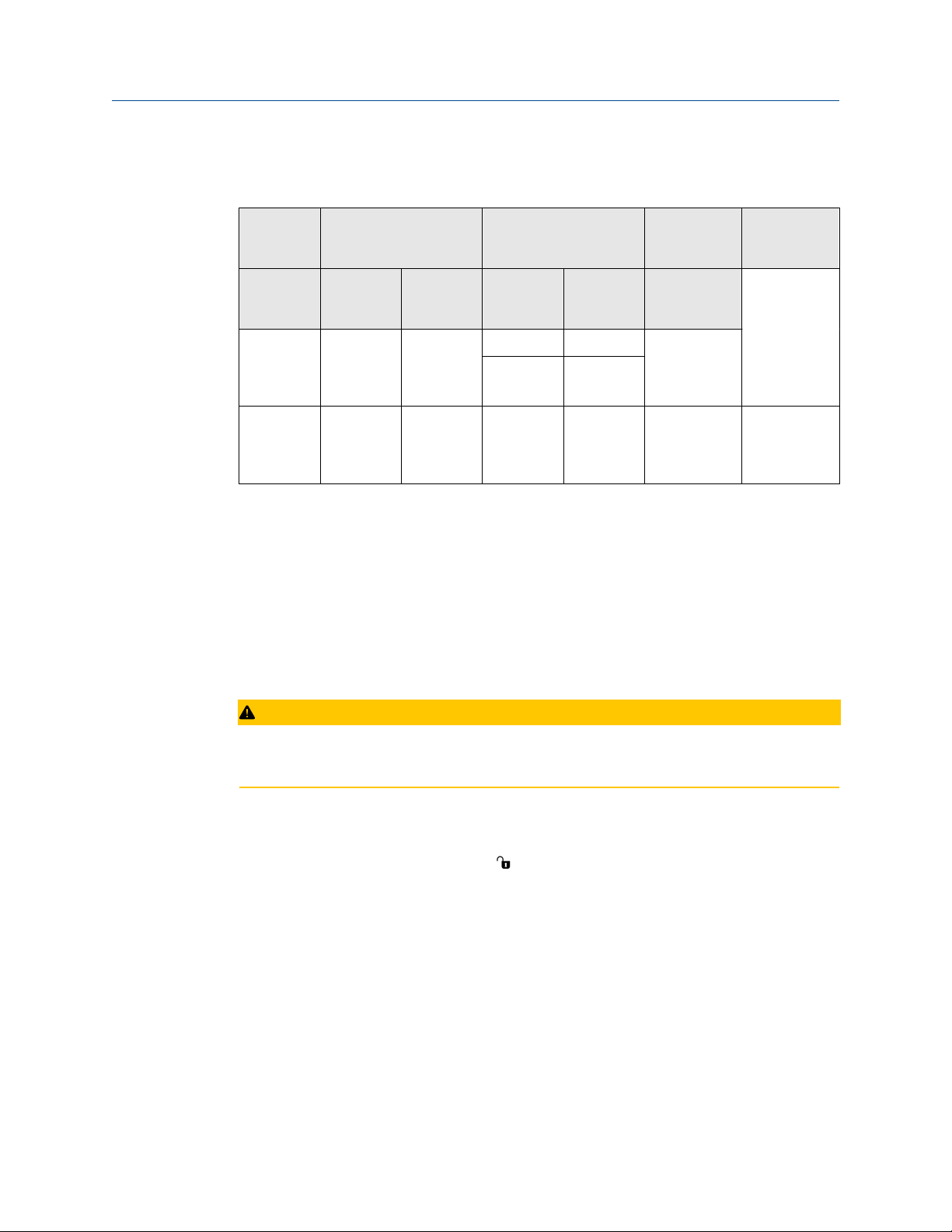
Example
Table 2-1: Rosemount 2051 Device Revisions and Files
Software
release
date
NAMUR
software
revision
August
2012
January
1998
(1) NAMUR Software Revision is located on the hardware tag of the device
(2) HART Software Revision can be read using a HART capable configuration tool.
(3) Device Driver file names use Device and DD Revision, e.g. 10_01. HART Protocol is designed to
enable legacy device driver revisions to continue to communicate with new HART devices. To
access new functionality, the new Device Driver must be downloaded. It is recommended to
download new Device Driver files to ensure full functionality.
(4) HART Revision 5 and 7 Selectable, Safety Certified, LOI, Scaled Variable, Configurable Alarms,
Expanded Engineering Units.
Identify device Find Device Driver Review
HART
software
(1)
revision
1.0.0 01 7 10 Rosemount
N/A 178 5 3 Rosemount
(2)
HART
universal
revision
Device
revision
5 9
(3)
Reference
manual
instructions
Changes to
software
2051
Reference
Manual
2051
Reference
Manual
Review
functionality
(4)
N/A
2.4 Configuration basics
CAUTION
Set all transmitter hardware adjustments during commissioning to avoid exposing the
transmitter electronics to the plant environment after installation.
The transmitter can be configured either before or after installation. Configuring the
transmitter on the bench using either a Field Communicator, AMS Device Manager, or LOI
ensures all transmitter components are in working order prior to installation. Verify that
the security switch is set in the unlock ( ) position in order to proceed with configuration.
See Figure 4-2 for switch location.
2.4.1
Configuring on the bench
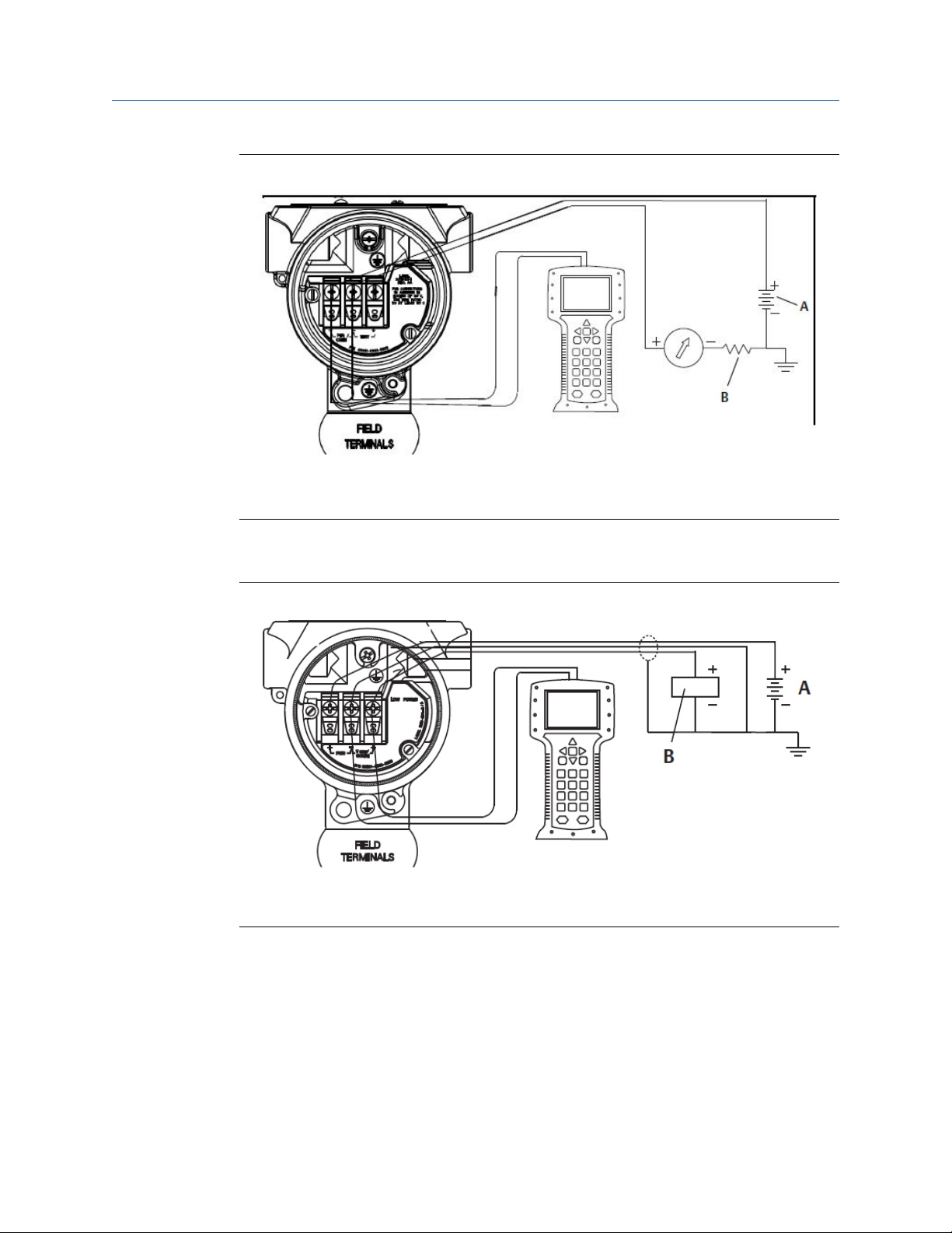
To configure on the bench, required equipment includes a power supply, and a Field
Communicator, AMS Device Manager, or an LOI (option M4). Wire equipment as shown in
Figure 2-1. To ensure successful HART® communication, a resistance of at least 250 Ωs
must be present between the transmitter and the power supply, see Power supply for
details. Connect the Field Communicator leads to the terminals labeled “COMM” on the
terminal block or 1–5 V configuration, wire as shown in Figure 2-1. The Field
Communicator is connected to the terminals labeled VOUT/COMM.
Reference Manual 13
Configuration Reference Manual
September 2020 00809-0100-4107
Figure 2-1: Wiring the Transmitter (4–20 mA HART)
A. Vdc supply
B. R L ≥ 250 (necessary for HART communication only)
2.4.2
Configuration tools
Figure 2-2: Wiring the Transmitter (1–5 Vdc Low Power)
A. DC power supply
B. Voltmeter
Configuring with a Field Communicator
There are two interfaces available with the Field Communicator: Traditional and
Dashboard interfaces. All steps using a Field Communicator will be described using
Dashboard interfaces. HART® shows the Device Dashboard interface. As stated in System
readiness, it is critical that the latest DD’s are loaded into the Field Communicator. Visit
Emerson.com or FieldCommGroup.org to download latest DD library.
Field Communicator menu trees and Fast Keys are available in Field Communicator Menu
Trees and Fast Keys.
14 Rosemount 2051 Pressure Transmitter

SAVE
1. Overview
2. Configure
3. Service Tools
2088 FT 45B
Online
Reference Manual Configuration
00809-0100-4107 September 2020
Figure 2-3: Device Dashboard
Configuring with AMS Device Manager
Full configuration capability with AMS Device Manager requires loading the most current
Device Descriptor (DD) for this device. Download the latest DD at Emerson.com or
FieldCommGroup.org.
Note
All steps using AMS Device Manager will be described using version 11.5.
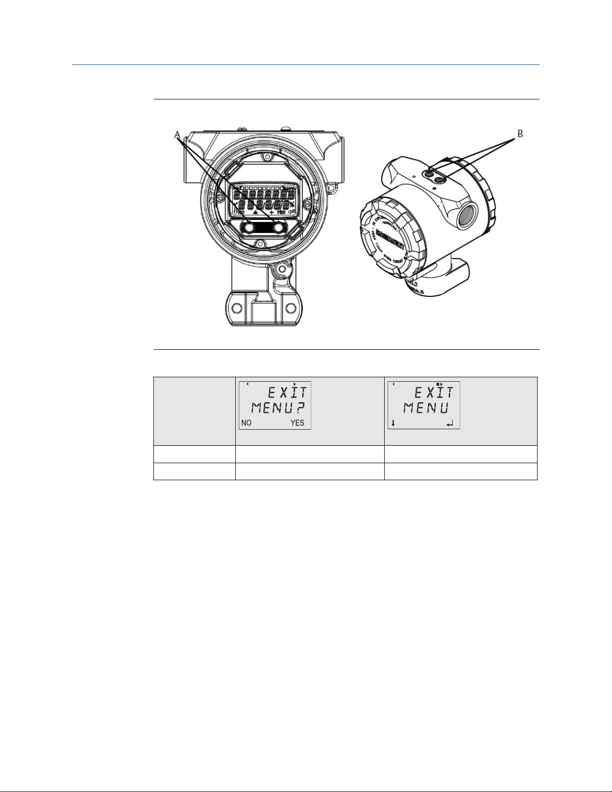
Configuring with a LOI
The LOI requires option code M4 to be ordered. To activate the LOI push either
configuration button. Configuration buttons are located on the LCD display (must remove
housing cover to access), or underneath the top tag of the transmitter. See Table 2-2 for
configuration button functionality and Figure 2-4 for configuration button location. When
using the LOI for configuration, several features require multiple screens for a successful
configuration. Data entered will be saved on a screen-by-screen basis; the LOI will indicate
this by flashing “SAVED” on the LCD display each time.
LOI menu trees are available in Local Operator Interface (LOI) Menu.
Reference Manual 15
Configuration Reference Manual
September 2020 00809-0100-4107
Figure 2-4: LOI Configuration Buttons
A. Internal configuration buttons B. External configuration buttons
Table 2-2: LOI Button Operation
Button
Left No SCROLL
Right Yes ENTER
2.4.3 Setting the loop to manual
Whenever sending or requesting data that would disrupt the loop or change the output of
the transmitter, set the process application loop to manual control. The Field
Communicator, AMS Device Manager, or the LOI will prompt you to set the loop to manual
when necessary. The prompt is only a reminder; acknowledging this prompt does not set
the loop to manual. It is necessary to set the loop to manual control as a separate
operation.
2.5 Verify configuration
It is recommended that various configuration parameters are verified prior to installation
into the process. The various parameters are detailed out for each configuration tool.
Depending on what configuration tool(s) are available follow the steps listed relevant to
each tool.
16 Rosemount 2051 Pressure Transmitter

Reference Manual Configuration
00809-0100-4107 September 2020
2.5.1 Verifying configuration with Field Communicator
Configuration parameters listed in Table 2-3 are to be reviewed prior to transmitter
installation. A Full list of configuration parameters that can be reviewed and configured
using a Field Communicator are located in Field Communicator Menu Trees and Fast Keys.
Fast key sequences for the latest DD are shown in Table 2-3. For Fast Key sequences for
legacy DD's contact your local Emerson Representative.
Table 2-3: Device Dashboard Fast Key sequence
From the HOME screen, enter the Fast Key sequences listed
Function Fast Key sequence
HART 7 HART 5
Alarm and Saturation Levels 2, 2, 2, 5 2, 2, 2, 5
Damping 2, 2, 1, 1, 5 2, 2, 1, 1, 5
Primary Variable 2, 1, 1, 4, 1 2, 1, 1, 4, 1
Range Values 2, 1, 1, 4 2, 1, 1, 4
Tag 2, 2, 7, 1, 1 2, 2, 7, 1, 1
Transfer Function 2, 2, 1, 1, 6 2, 2, 1, 1, 6
Units 2, 2, 1, 1, 4 2, 2, 1, 1, 4
2.5.2 Verifying configuration with AMS Device Manager
Right select on the device and select Configuration Properties from the menu. Navigate
the tabs to review the transmitter configuration data.
2.5.3
Verifying configuration with LOI
Press any configuration button to activate the LOI. Select VIEW CONFIG to review the
below parameters. Use the configuration buttons to navigate through the menu. The
parameters to be reviewed prior to installation include:
• Tag
• Units
• Transfer function
• Alarm and saturation levels
• Primary variable
• Range values
• Damping
Reference Manual 17

Configuration Reference Manual
September 2020 00809-0100-4107
2.5.4 Verifying process variables configuration
This section describes how to verify that the correct process variables are selected.
Verifying process variables with a Field Communicator
From the HOME screen, enter the Fast Key sequence.
Device Dashboard Fast Keys 3, 2, 1
Verifying process variables with AMS Device Manager
Procedure
1. Right click the device and select Overview from the menu.
2. Select the All Variables button to display the primary, secondary, tertiary and
quaternary variables.
2.6 Basic setup of the transmitter
This section goes through the necessary steps for basic setup of a pressure transmitter.
When installing in DP level or DP flow applications, refer to Configuring scaled variable for
setup instructions.
2.6.1
Setting pressure units
The pressure unit command sets the unit of measure for the reported pressure.
Setting pressure units with a Field Communicator
From the HOME screen, enter the Fast Key sequence.
Device Dashboard Fast Keys
Setting pressure units with AMS Device Manager
Procedure
1. Right select the device and select Configure.
2. Select Manual Setup and select desired units from Pressure Units dropdown menu.
3. Select Send when complete.
2, 2, 1, 1, 4
Setting pressure units with a LOI
Follow Figure 2-5 to select desired pressure and temperature units. Use the SCROLL and
ENTER buttons to select desired unit. Save by selecting SAVE as indicated on the LCD
display screen.
18 Rosemount 2051 Pressure Transmitter
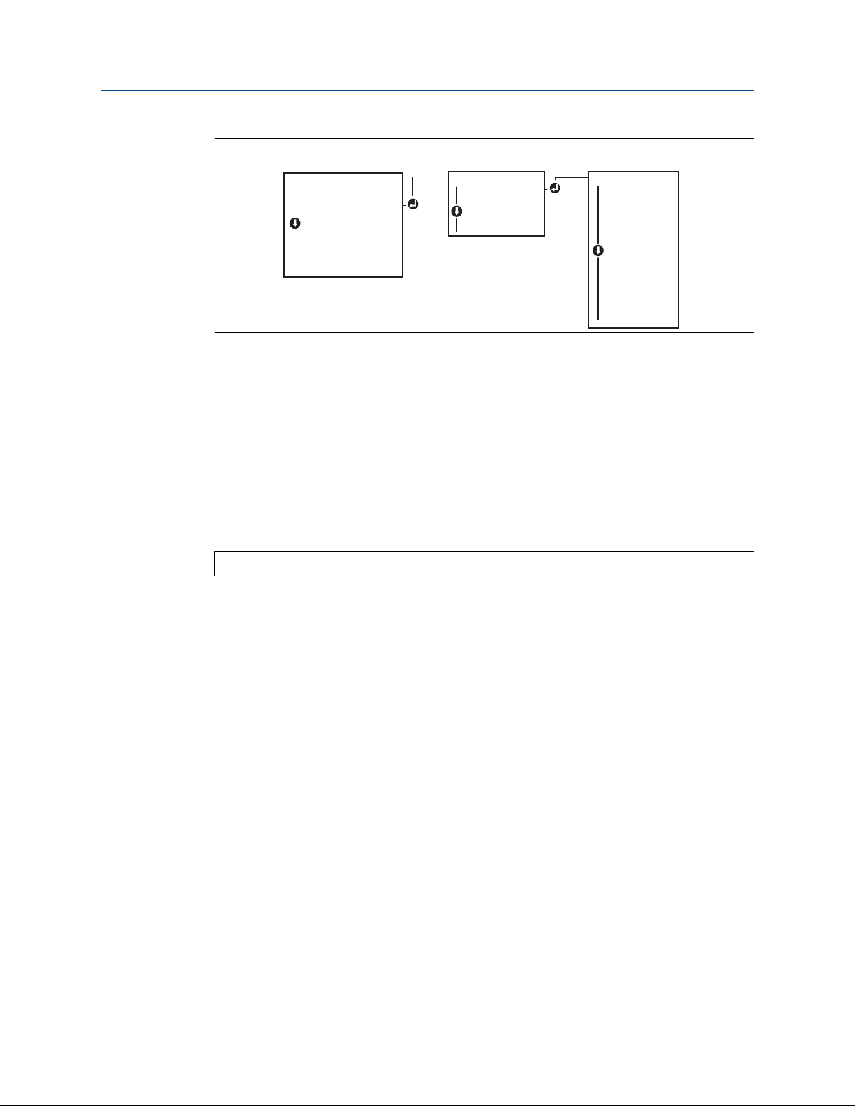
UNITS
PRESS UNITS
TEMP UNITS
BACK TO MENU
EXIT MENU
PRESS UNITS
INH2O
MMHG
CMHG0C
MHG0C
PSI
PSF
ATM
TORR
PA
KPA
...
VIEW CONFIG
ZERO TRIM
UNITS
RERANGE
LOOP TEST
DISPLAY
EXTENDED MENU
EXIT MENU
Reference Manual Configuration
00809-0100-4107 September 2020
Figure 2-5: Selecting Units with LOI
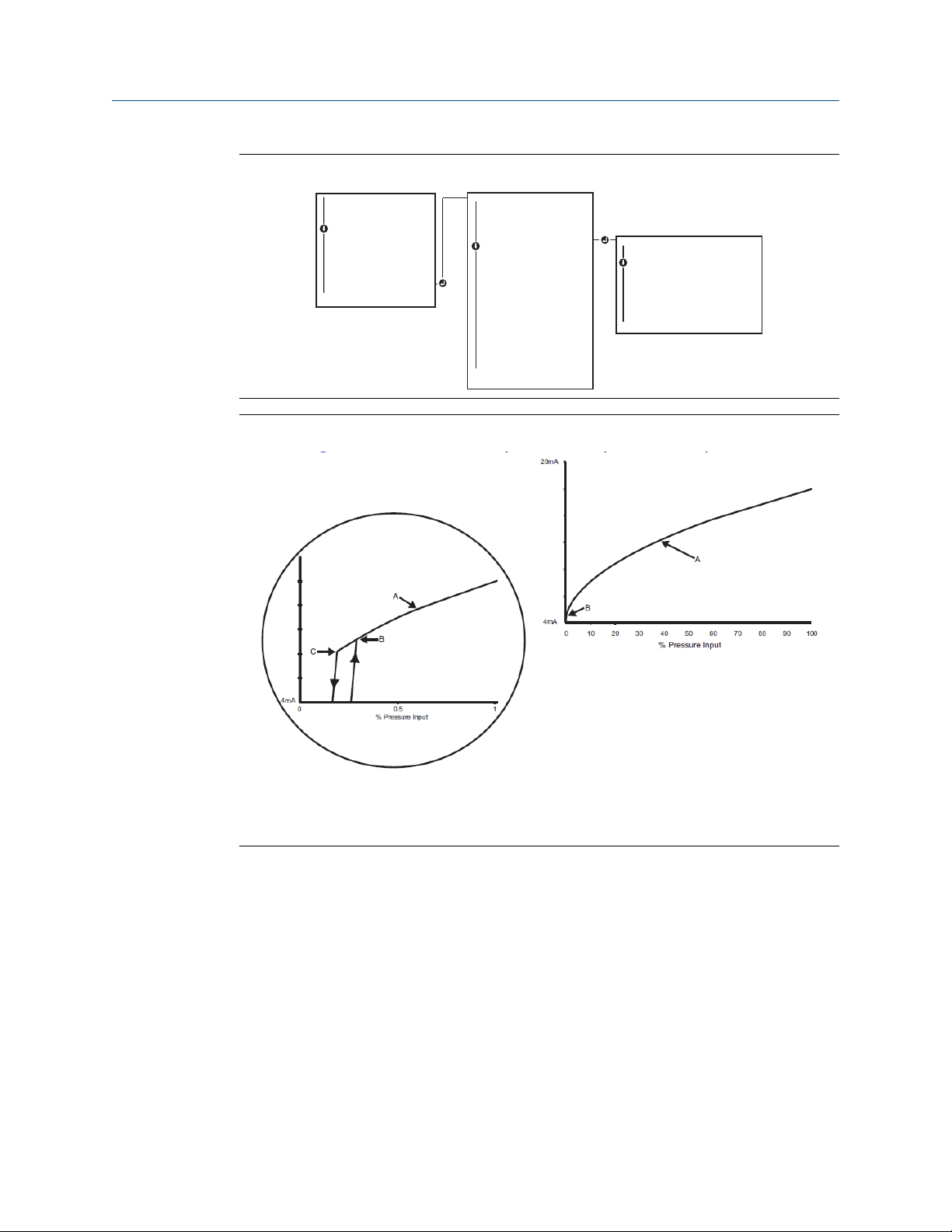
2.6.2 Setting transmitter output (transfer function)
The transmitter has two output settings: Linear and square root. As shown in Figure 2-7,
activating the square root options makes analog output proportional to flow, and includes
a fixed low flow cutoff at five percent.
However, for DP Flow and DP Level applications it is recommended to use scaled variable.
Refer to Configuring scaled variable for setup instructions.
Setting transmitter output with a Field Communicator
From the HOME screen, enter the Fast Key sequence.
Device Dashboard Fast Keys
2, 2, 1, 1, 6
Setting transmitter output with AMS Device Manager
Procedure
1. Right click on the device and select Configure.
2. Select Manual Setup and choose output type from analog output transfer function
and select Send.
3. Carefully read the warning and select Yes if it is safe to apply the changes.
Setting transmitter output with a LOI
Reference Figure 2-6 to select either linear or square root transfer function using the LOI.
Reference Manual 19
EXTENDED MENU
CALIBRAT
DAMPING
TRANSFER FUNCT
SCALED VARIAB
ASSIGN PV
TAG
ALARM SAT
VALUES
PASSWORD
SIMLATE
HART REV
BACK TO MENU
EXIT MENU
TRANSFER FUNCT
LINEAR TRANSFER
FUNCTION
SQR ROOT TRANSFER
FUNCTION
BACK TO MENU
EXIT MENU
VIEW CONFIG
ZERO TRIM
UNITS
RERANGE
LOOP TEST
DISPLAY
EXTENDED MENU
EXIT MENU
Configuration Reference Manual
September 2020 00809-0100-4107
Figure 2-6: Set Output with LOI
Figure 2-7: 4–20 mA HART Square Root Output Transition Point
A. Square root curve
B. Five percent transition point
C. Four percent transition point
2.6.3
Rerange the transmitter
The range values command sets each of the lower and upper range analog values (4 and
20 mA/1–5 Vdc points) to a pressure. The lower range point represents 0 percent of range
and the upper range point represents 100 percent of range. In practice, the transmitter
range values may be changed as often as necessary to reflect changing process
requirements.
Select from one of the methods below to rerange the transmitter. Each method is unique;
20 Rosemount 2051 Pressure Transmitter
examine all options closely before deciding which method works best for your process.
• Rerange by manually setting range points with a Field Communicator, AMS Device
Manager, or LOI.
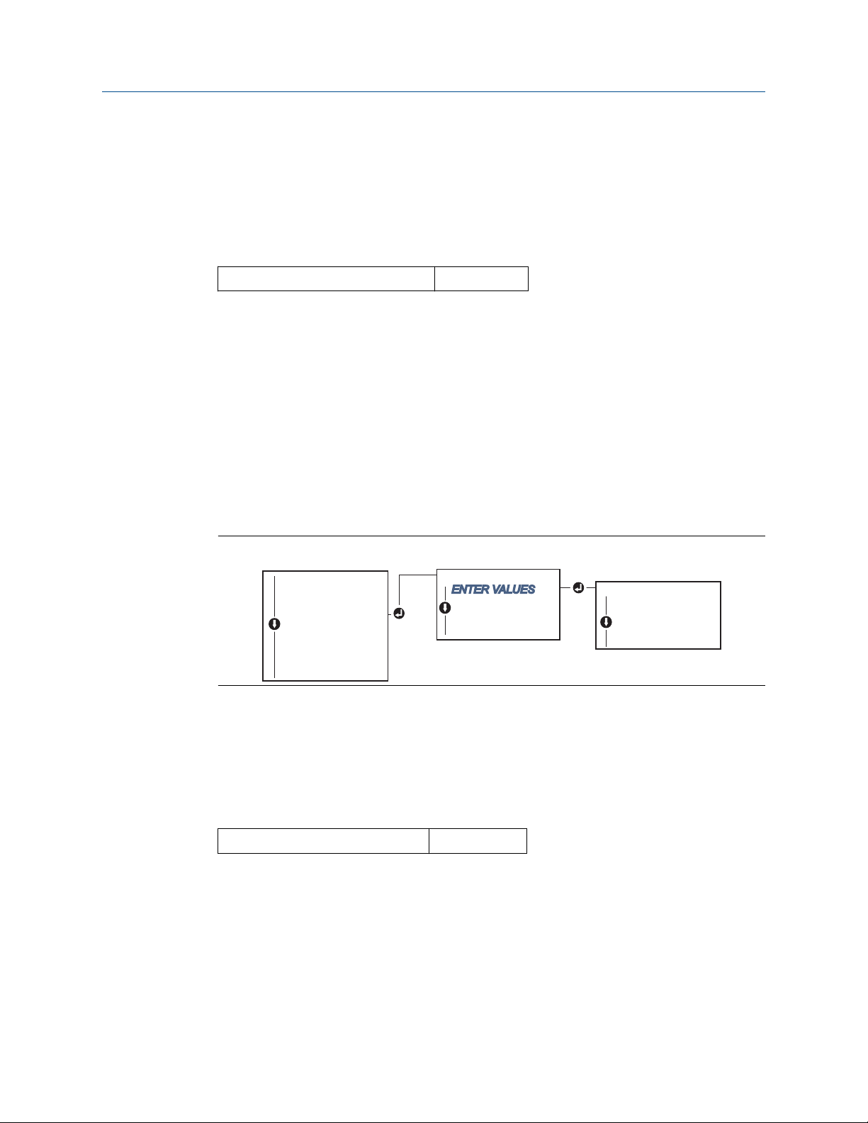
RERANGE
ENTER VALUES
APPLY VALUES
BACK TO MENU
EXIT MENU
ENTER VALUES
LRV
URV
BACK TO MENU
EXIT MENU
VIEW CONFIG
ZERO TRIM
UNITS
RERANGE
LOOP TEST
DISPLAY
EXTENDED MENU
EXIT MENU
Reference Manual Configuration
00809-0100-4107 September 2020
• Rerange with a pressure input source and a Field Communicator, AMS Device Manager,
LOI, or local zero and span buttons.
Manually rerange the transmitter by entering range points
Entering range points with a Field Communicator
From the HOME screen, enter the Fast Key sequence.
Device Dashboard Fast Keys 2, 2, 2, 1
Entering range points with AMS Device Manager
Procedure
1. Right select the device and select Configure.
2. Select Manual Setup and select Analog Output.
3. Enter upper and lower range values in the Range Limits box and click Send.
4. Carefully read the warning and click Yes if it is safe to apply the changes.
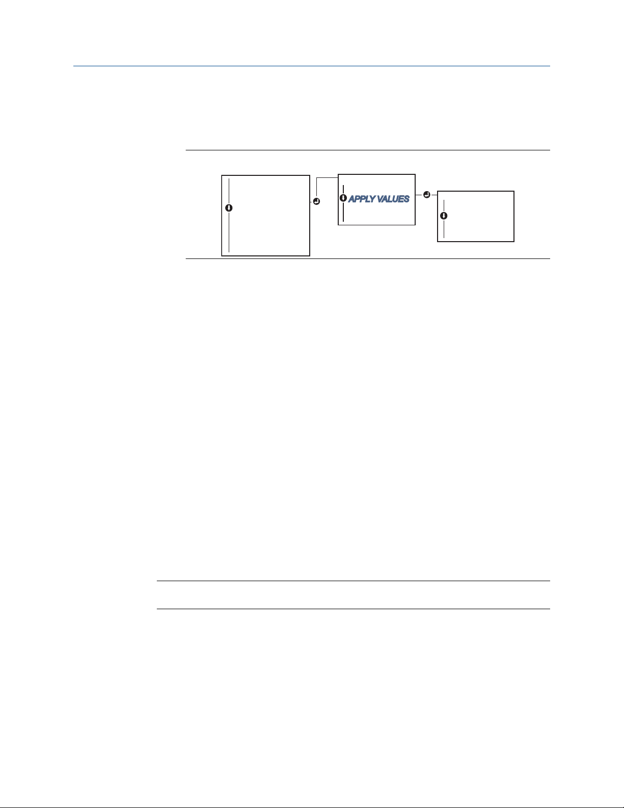
Entering range points with a LOI
Reference Figure 2-8 to rerange the transmitter using the LOI. Enter values using SCROLL
and ENTER buttons.
Figure 2-8: Rerange with LOI
Rerange the transmitter with applied pressure source
Reranging using an applied pressure source is a way of reranging the transmitter without
entering specific 4 and 20 mA (1–5 Vdc) points.
Rerange with an applied pressure source using a Field Communicator
From the HOME screen, enter the Fast Key sequence
Device Dashboard Fast Keys
Rerange with an applied pressure source using AMS Device Manager
2, 2, 2, 2
Reference Manual 21
Procedure
1. Right select the device, select Configure.
2. Select the Analog Output tab.
3. Select Range by Applying Pressure button and follow the screen prompts range the
transmitter.
RERANGE
ENTER VALUES
APPLY VALUES
BACK TO MENU
EXIT MENU
APPLY VALUES
LRV
URV
BACK TO MENU
EXIT MENU
VIEW CONFIG
ZERO TRIM
UNITS
RERANGE
LOOP TEST
DISPLAY
EXTENDED MENU
EXIT MENU
Configuration Reference Manual
September 2020 00809-0100-4107
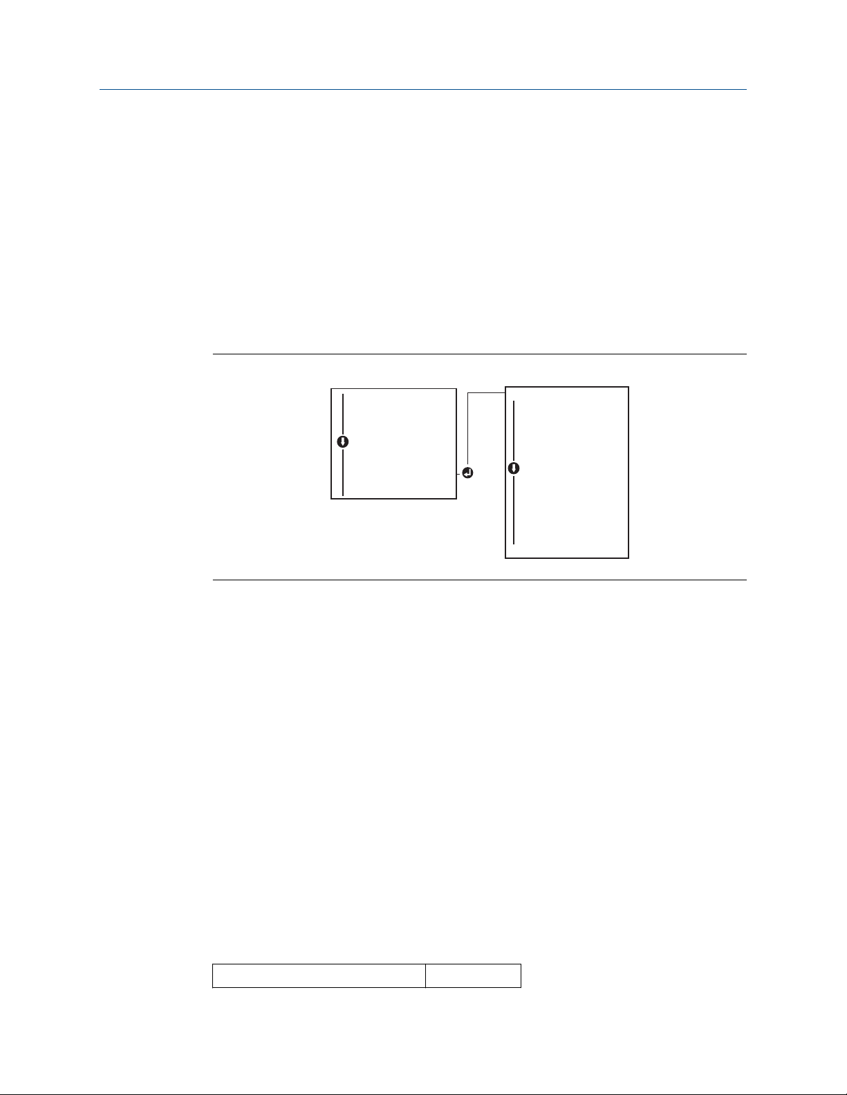
Rerange with an applied pressure source using a Field Communicator
Use Figure 2-9 to manually rerange the device using an applied pressure source with
an LOI.
Figure 2-9: Rerange with Applied Pressure Using LOI
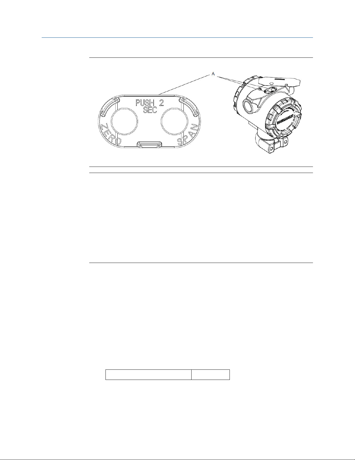
Rerange with an applied pressure source using local zero and span buttons
If ordered, local zero and span buttons (option code D4) can be used to rerange the
transmitter with an applied pressure. Refer to Figure 2-10 for analog zero and span button
location.
To rerange the transmitter using the span and zero buttons, perform the following
procedure:
Procedure
1. Loosen the screw holding the top tag of the transmitter housing. Rotate the label to
expose the zero and span buttons.
2. Confirm device has local zero and span buttons by verifying blue retainer under the
tag.
3. Apply transmitter pressure.
4. Rerange the transmitter.
a) To change the zero (4 mA/1 V point) while maintaining the span: press and
hold zero button for at least two seconds then release.
b) To change the span (20 mA/5 V point) while maintaining the zero point:
press and hold the span button for at least two seconds and then release.
Example
Note
4 mA and 20 mA points must maintain the minimum span.
22 Rosemount 2051 Pressure Transmitter
Reference Manual Configuration
00809-0100-4107 September 2020
Figure 2-10: Analog Zero and Span Buttons
A. Zero and span buttons
Note
• If the transmitter security is on, adjustments to the zero and span will not be able to be
made. Refer to Configure security and simulation for security information.
2.6.4
• The span is maintained when the 4 mA/1 V point is set. The span changes when the 20
mA 5 V point is set. If the lower range point is set to a value that causes the upper range
point to exceed the sensor limit, the upper range point is automatically set to the
sensor limit, and the span is adjusted accordingly.
• Regardless of the range points, the transmitter measure and report all readings within
the digital limits of the sensor. For example, if the 4 and 20 mA(1–5 Vdc) points are set
to 0 and 10 inH2O, and the transmitter detects a pressure of 25 inH2O, it digitally
outputs the 25 inH2O reading and a 250 percent of range reading.
Damping
The damping command changes the response time of the transmitter; higher values can
smooth variations in output readings caused by rapid input changes. Determine the
appropriate damping setting based on the necessary response time, signal stability, and
other requirements of the loop dynamics within your system. The damping command
utilizes floating point configuration allowing the user to input any damping value within
0.0–60.0 seconds.
Damping with a Field Communicator
Procedure
1. From the HOME screen, enter the Fast Key sequence.
Device Dashboard Fast Keys
2. Enter desired Damping Value and select APPLY.
Reference Manual 23
2, 2, 1, 1, 5
EXTENDED MENU
CALIBRAT
DAMPING
TRANSFER FUNCT
SCALED VARIAB
ASSIGN PV
TAG
ALARM SAT VALUES
PASSWORD
SIMLATE
HART REV
BACK TO MENU
EXIT MENU
VIEW CONFIG
ZERO TRIM
UNITS
RERANGE
LOOP TEST
DISPLAY
EXTENDED MENU
EXIT MENU
Configuration Reference Manual
September 2020 00809-0100-4107
Damping with AMS Device Manager
Procedure
1. Right select the device and select Configure.
2. Select Manual Setup.
3. Within the Pressure Setup box, enter desired damping value and click Send.
4. Carefully read the warning and click Yes if it is safe to apply the changes.
Damping with a LOI
Reference Figure 2-11 to enter damping values using an LOI.
Figure 2-11: Damping with LOI
2.7 Configuring the LCD display
2.7.1
24 Rosemount 2051 Pressure Transmitter
The LCD display configuration command allows customization of the LCD display to suit
application requirements. The LCD display will alternate between the selected items.
• Pressure Units
• % of Range
• Scaled Variable
• Sensor Temperature
• mA/Vdc Output
In the following instructions, the LCD display can also be configured to display
configuration information during the device startup. Select Review Parameters at Startup
to enable or disable this functionality.
Reference Configuring the LCD display with LOI for image of LCD display screen.
Configuring LCD display with a Field Communicator
From the HOME screen, enter the Fast Key sequence.
Device Dashboard Fast Keys
2, 2, 4
DISPLAY
PRESS (on/off)
SCALED (on/off)
TEMP (on/off)
%RANGE (on/off)
ANALOG (on/off)
STRTUP (on/off)
BACK TO MENU
EXIT MENU
VIEW CONFIG
ZERO TRIM
UNITS
RERANGE
LOOP TEST
DISPLAY
EXTENDED MENU
EXIT MENU
Reference Manual Configuration
00809-0100-4107 September 2020
2.7.2 Configuring LCD display with AMS Device Manager
Procedure
1. Right select on the device and select Configure.
2. Select Manual Setup, select the Display tab.
3. Select desired display options and click Send.
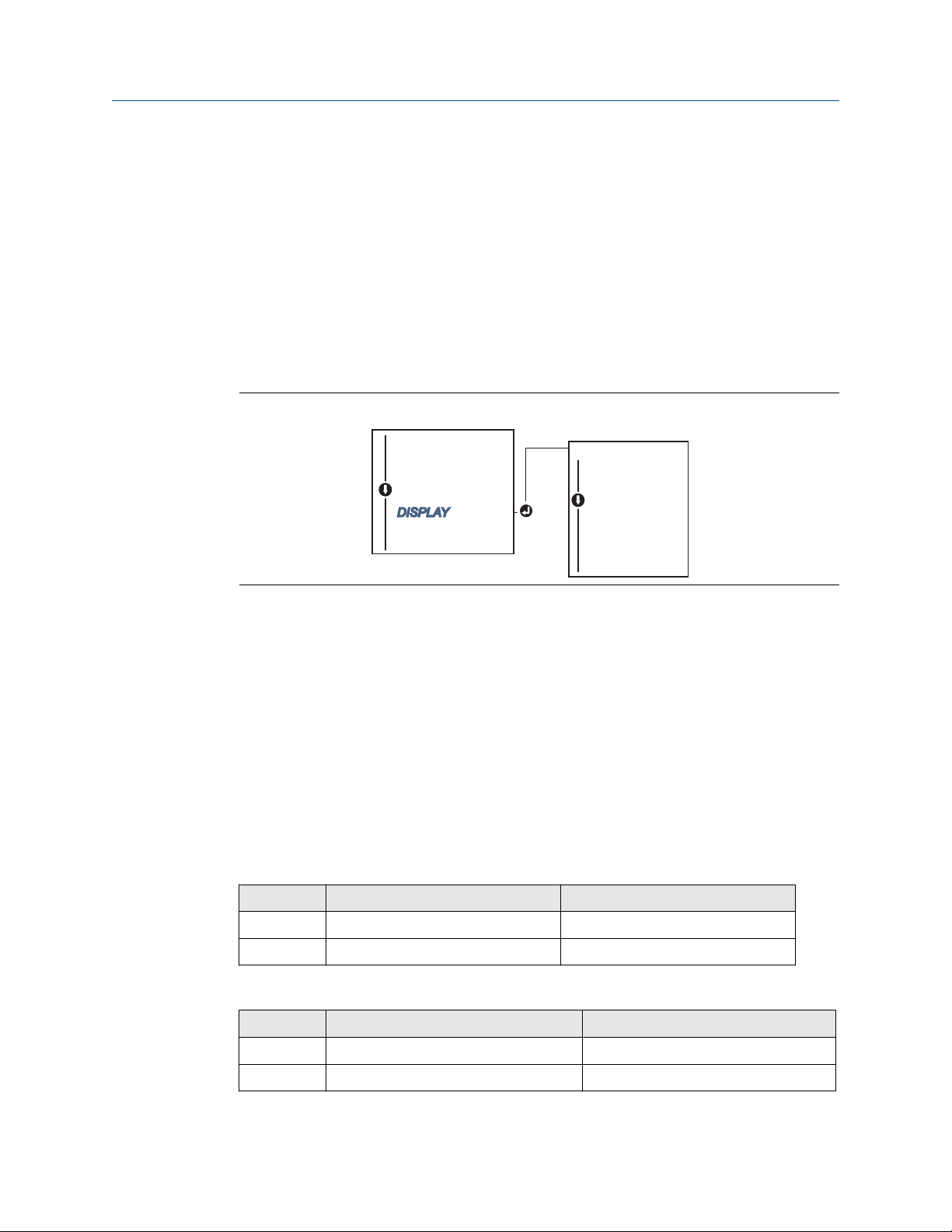
2.7.3 Configuring LCD display with a LOI
Refer to Figure 2-12 for LCD display configuration using a LOI.
Figure 2-12: Display with LOI
2.8 Detailed transmitter setup
2.8.1 Configuring alarm and saturation levels
Reference Manual 25
In normal operation, the transmitter will drive the output in response to pressure from the
lower to upper saturation points. If the pressure goes outside the sensor limits, or if the
output would be beyond the saturation points, the output will be limited to the associated
saturation point.
The transmitter automatically and continuously performs self-diagnostic routines. If the
self-diagnostic routines detect a failure, the transmitter drives the output to configured
alarm and value based on the position of the alarm switch. See Setting transmitter alarm.
Table 2-4: Rosemount Alarm and Saturation Values
Level 4–20 mA (1–5 Vdc) saturation 4–20 mA (1–5 Vdc alarm
Low 3.90 mA (0.97 V) ≤ 3.75 mA (0.95 V)
High 20.80 mA (5.20 V) ≥ 21.75 mA (5.40 V)
Table 2-5: NAMUR-Compliant Alarm and Saturation Values
Level 4–20 mA (1–5 Vdc) saturation 4–20 mA (1–5 Vdc) alarm
Low 3.80 mA (0.95 V) ≤ 3.60 mA (0.90 V) (.90 –.95 V)
High 20.50 mA (5.13 V) ≥22.50 mA (5.63 V) (5.05 –5.75 V)

Configuration Reference Manual
September 2020 00809-0100-4107
Table 2-6: Custom Alarm and Saturation Values
Level 4–20 mA (1–5 Vdc) saturation 4–20 mA (1–5 Vdc) alarm
Low 3.70 mA– 3.90 mA (.90 –.95 V) 3.60–3.80 mA (.90 –.95 V)
High 20.10 mA –22.90 mA (5.025 –5.725 V) 20.20 mA – 23.00 mA (5.05 –5.75 V)
Failure mode alarm and saturation levels can be configured using a Field Communicator,
AMS Device Manager, and the LOI. The following limitations exist for custom levels:
• Low alarm level must be less than the low saturation level
• High alarm level must be higher than the high saturation level
• Alarm and saturation levels must be separated by at least 0.1 mA (0.025 Vdc)
The configuration tool will provide an error message if the configuration rule is violated.
Note
Transmitters set to HART® multidrop mode send all saturation and alarm information
digitally; saturation and alarm conditions will not affect the analog output. See also
Establishing multidrop communication.
Configuring alarm and saturation levels using a Field Communicator
From the HOME screen, enter the Fast Key sequence.
Device Dashboard Fast Keys
2, 2, 2, 5
Configuring alarm and saturation levels with AMS Device Manager
Procedure
1. Right select on the device, and select Configure.
2. Select Configure Alarm and Saturation Levels button.
3. Follow screen prompts to configure Alarm and Saturation Levels.
Configuring alarm and saturation levels using LOI
Refer to Figure 2-13 for instructions to configure alarm and saturation levels.
26 Rosemount 2051 Pressure Transmitter
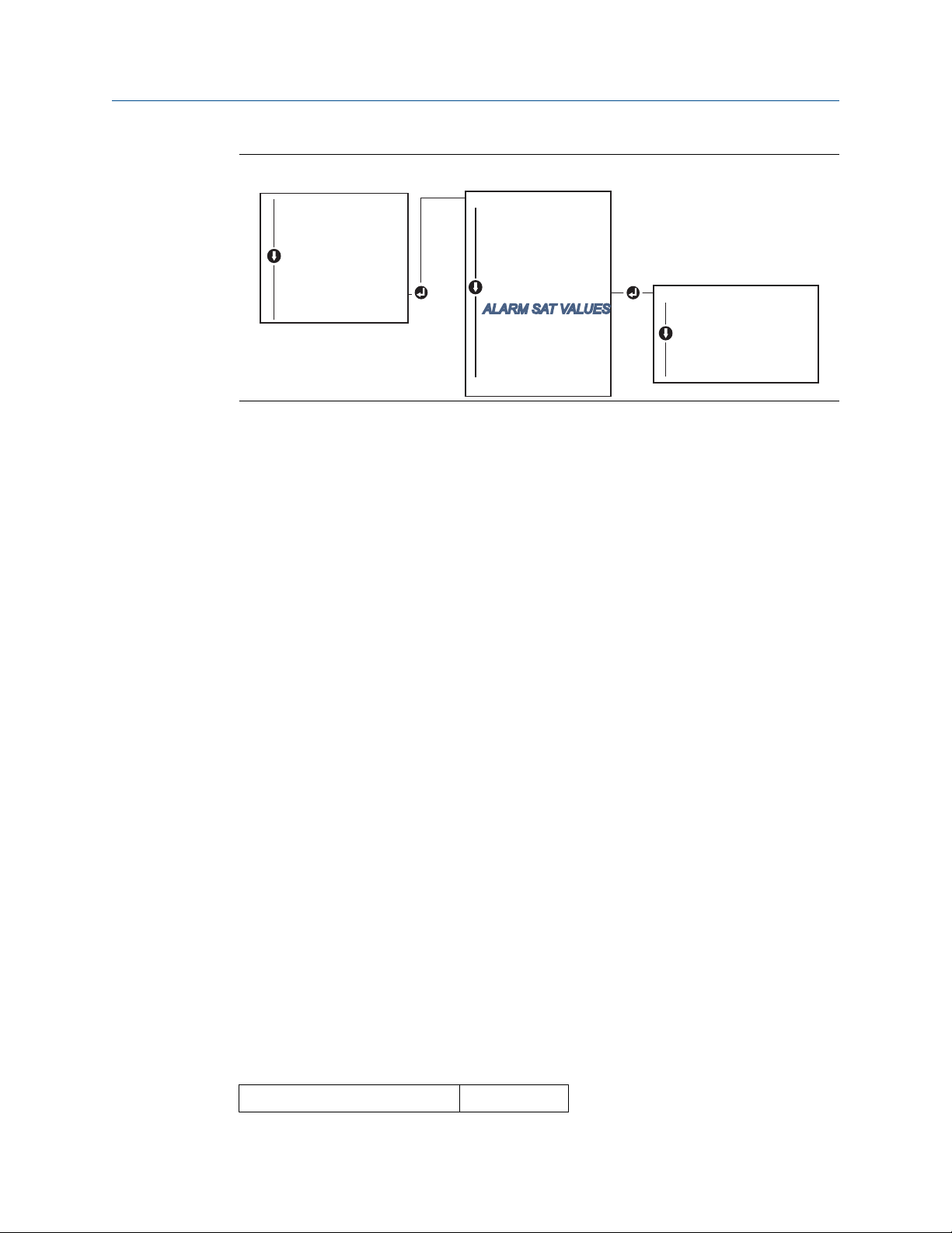
EXTENDED MENU
CALIBRAT
DAMPING
TRANSFER FUNCT
SCALED VARIAB
ASSIGN PV
TAG
ALARM SAT VALUES
PASSWORD
SIMULATE
HART REV
BACK TO MENU
EXIT MENU
ALARM SAT VALUES
ROSEMOUNT VALUES
NAMUR VALUES
OTHER VALUES
BACK TO MENU
EXIT MENU
VIEW CONFIG
ZERO TRIM
UNITS
RERANGE
LOOP TEST
DISPLAY
EXTENDED MENU
EXIT MENU
Reference Manual Configuration
00809-0100-4107 September 2020
Figure 2-13: Configuring Alarm and Saturation with LOI
2.8.2 Configuring scaled variable
The Scaled Variable configuration allows the user to create a relationship/conversion
between the pressure units and user-defined/custom units. There are two use cases for
Scaled Variable. The first use case is to allow custom units to be displayed on the
transmitter's LCD/LOI display. The second use case is to allow custom units to drive the
transmitter's 4–20 mA (1–5 Vdc) output.
If the user desires custom units to drive the 4–20 mA (1–5 Vdc) output, Scaled Variable
must be re-mapped as the primary variable. Refer to Re-mapping device variables.
The Scaled Variable configuration defines the following items:
• Scaled Variable units - custom units to be displayed.
• Scaled data options - defines the transfer function for the application (linear and square
root)
• Pressure value position 1 - lower known value point with consideration of linear offset.
• Scaled Variable value position 1 - custom unit equivalent to the lower known value
point.
• Pressure value position 2 - upper known value point
• Scaled Variable value position 2 - custom unit equivalent to the upper known value
point
• Linear offset - the value required to zero out pressures effecting the desired pressure
reading.
• Low flow cutoff - point at which output is driven to zero to prevent problems caused by
process noise. It is highly recommended to use the low flow cutoff function in order to
have a stable output and avoid problems due to process noise at a low flow or no flow
condition. A low flow cutoff value that is practical for the flow element in the
application should be entered.
Reference Manual 27
Configuring scaled variable using a Field Communicator
From the HOME screen, enter the Fast Key sequence.
Device Dashboard Fast Keys
2, 1, 4, 7
EXTENDED MENU
CALIBRAT
DAMPING
TRANSFER FUNCT
SCALED VARIAB
ASSIGN PV
TAG
ALARM SAT VALUES
PASSWORD
SIMLATE
HART REV
BACK TO MENU
EXIT MENU
SCALED VARIAB
VIEW SCALED
CONFIG SCALED
BACK TO MENU
EXIT MENU
VIEW CONFIG
ZERO TRIM
UNITS
RERANGE
LOOP TEST
DISPLAY
EXTENDED MENU
EXIT MENU
Configuration Reference Manual
September 2020 00809-0100-4107
Procedure
Follow the screen prompts to configure Scaled Variable.
a) When configuring for level, select Linear under Select Scaled data options.
b) When configuring for flow, select Square Root under Select Scaled data options.
Configuring scaled variable using AMS Device Manager
Procedure
1. Right select on the device and, select Configure.
2. Select the Scaled Variable tab and select the Scaled Variable button.
3. Follow screen prompts to configure Scaled Variable
a) When configuring for level applications, select Linear under Select Scaled
data options.
b) When configuring for flow applications, select Square Root under Select
Scaled data options.
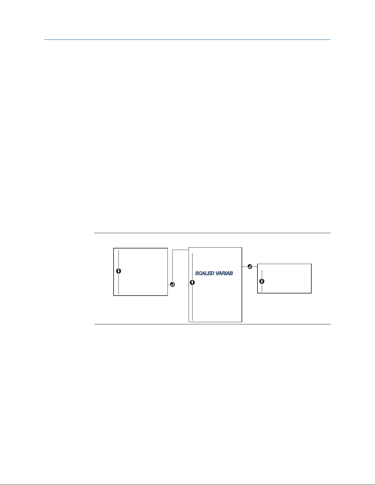
Configuring scaled variable using a LOI
Refer to Figure 2-14 for instructions to configure Scaled Variable using a LOI.
Figure 2-14: Configuring Scaled Variable Using a LOI
28 Rosemount 2051 Pressure Transmitter

H
L
230-in.
200-in.
12-in.
0.94 sg
Reference Manual Configuration
00809-0100-4107 September 2020
DP level example
Figure 2-15: Example Tank
A differential transmitter is used in a level application. Once installed on an empty tank
and taps vented, the process variable reading is –209.4 inH2O. The process variable
reading is the head pressure created by fill fluid in the capillary. Based on Table 2-7, the
scaled variable configuration would be as follows:
Table 2-7: Scaled Variable Configuration for Tank Application
Scaled variable units: inch
Scaled data 13: linear
Pressure value position 1: 0 inH2O
Scaled Variable position 1: 12-in.
Pressure value position 2: 188 inH2O
Scaled Variable position 2: 212-in.
Linear offset: –209.4 inH2O
DP flow example
A differential pressure transmitter is used in conjunction with an orifice plate in a flow
application where the differential pressure at full scale flow is 125 inH2O. In this particular
application, the flow rate at full scale flow is 20,000 gallons of water per hour. It is highly
recommended to use the low flow cutoff function in order to have a stable output and
avoid problems due to process noise at a low flow or no flow condition. A low flow cutoff
value that is practical for the flow element in the application should be entered. In this
Reference Manual 29

Configuration Reference Manual
September 2020 00809-0100-4107
particular example, the low flow cutoff value is 1000 gallons of water per hour. Based on
this information, the Scaled Variable configuration would be as follows:
Table 2-8: Scaled Variable Configuration for Flow Application
Scaled Variable units: gal/h
Scaled data options: square root
Pressure value position 2: 125 inH2O
Scaled Variable position 2: 20,000 gal/h
Low Flow Cutoff: 1000 gal/h
Note
Pressure value position 1 and Scaled Variable position 1 are always set to zero for a flow
application. No configuration of these values is required.
2.8.3
Re-mapping device variables
The re-mapping function allows the transmitter primary, secondary, tertiary, and
quaternary variables (PV, 2V, 3V, and 4V) to be configured as desired. The PV can be
remapped with a Field Communicator, AMS Device Manager, or a LOI. Variables (2V, 3V,
and 4V) can only be re-mapped via Field Communicator or AMS Device Manager.
Note
The variable assigned to the primary variable drives the 4–20 mA (1–5 Vdc) output. This
value can be selected as Pressure or Scaled Variable. The 2, 3, and 4 variables only apply if
HART® burst mode is being used.
Re-mapping using a Field Communicator
From the HOME screen, enter the Fast Key sequence.
Fast Keys
Re-mapping using AMS Device Manager
Procedure
1. Right select the device and select Configure.
2. Select Manual Setup and click on the HART tab.
3. Assign Primary, secondary, tertiary, and quaternary variables under Variable
Mapping.
4. Select Send.
5. Carefully read the warning and select Yes if it is safe to apply the changes.
2, 1, 1, 3
Re-mapping using LOI
Refer to Figure 2-16 for instructions to remap the primary variable using a LOI.
30 Rosemount 2051 Pressure Transmitter
Loading...