

Rosemount Manual: Rack-Mount Fire Controller with UV Detection using UVC120 Head | Rosemount Manuals & Guides

MODEL #: R1F, R2F & R4F-UV and UV C120
ULTRAVIOLET FIRE DETECTION SYSTEM
1, 2 and 4 Channel Rack Mount Controller
with the UVC120 Detector
ISO
Part Number: MAN-0025-00 Rev 2
November 2003
9001
Certified Company


Copyright © 20032 Net Safety M onitoring I nc .
Printed in Canada
This manual is provided for informational purposes only. Alt hough the informati on c ontained in
this manual is believed to be acc ur ate, it c ould include technical inaccuraci es or t y pogr aphical
errors. Changes are, therefore, periodically made to the infor mation within this document and
incorporat ed without notice into subsequent rev isions of the manual. Net S afety Monitoring I nc .
assumes no responsibility for any errors that may be contained within thi s manual.
This manual is a guide for the use of a 1, 2 and 4 Channel Rack Mount Cont r oller and the dat a
and procedures contained within this document have been ver ifi ed and ar e believed to be
adequate for the intended use of the controller. If the controller or procedures are used for
purposes other than as described in t he manual without receiving pri or c onfirmation of v alidit y or
suitability, Net Safety Monitoring Inc. does not guarantee the results and assumes no obligation
or liability.
No part of this manual may be copied, disseminated or distributed wit hout the express writt en
consent of Net S afety Monitoring I nc .
Net Safety Monitor ing Inc. products, are caref ully designed and manufactur ed from high qualit y
components and can be expected to provide many years of t rouble fr ee service. Each product is
thoroughly t est ed, inspected and calibrated prior to shipment . Failur es can oc c ur whic h ar e
beyond the control of the manufacturer. Fai lures can be mi nimiz ed by adher ing to the operat ing
and maint enanc e instructi ons herein. Where the absolute greatest of rel iability is required,
redundancy should be designed i nto the system.
Net Safety Monitor ing Inc., warrant s i ts sensors and detectors against defect iv e par ts and
workmanship for a period of 24 months f r om date of purchase and other elect r onic assembli es
for 36 months from date of pur c hase.
No other warranties or liability, expressed or implied, will be honoured by Net Saf ety Monitor ing
INC
Contact Net Safety Monitoring I nc . or an authorized distributor for detai ls.

Table of Contents
Unit I GENERAL INFORMATION .................................- 1 -
DESCRIPTION .......................................................... - 1 -
FEATURES............................................................. - 1 -
CONTROLLER SPECIFICATIONS ........................................... - 1 -
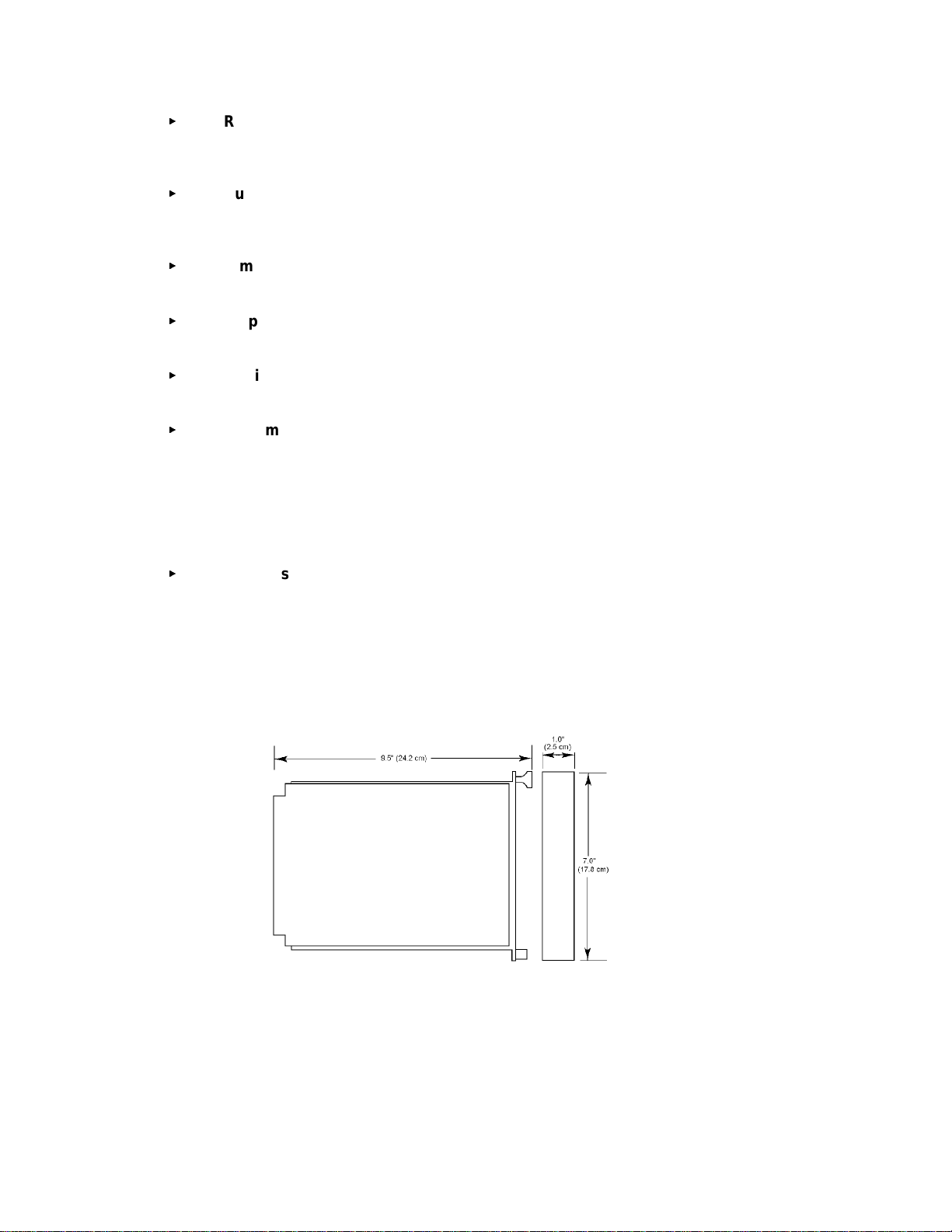
Figure 1 - Controller Dimensions....................................... - 2 -
DETECTOR SPECIFICATIONS ............................................. - 3 -
Figure 2b - Swivel Mount Dimensions ................................... - 3 -
Figure 2a - Detector Dimensions....................................... - 3 -
BASIC OPERATION - CONTROLLER ........................................ - 4 -
Figure 3 - Controller
Face-Plate ................................................. - 4 -
CONTROLLER FACEPLATE DESCRIPTION............................. - 4 -
OUTPUTS ....................................................... - 4 -
Table 1 - Selectable Output Options .................................... - 5 -
Figure 4 - Jumper Selections for an Isolated or Non-isolated Current Output...... - 5 -
PROGRAMMING OPTIONS.......................................... - 5 -
EXTERNAL RESET ................................................ - 6 -
AUTOMATIC DIAGNOSTICS AND FAULT IDENTIFICATION ................ - 6 -
VOTING LOGIC (not applicable to R1F)................................. - 6 -
DETECTOR ............................................................ - 6 -
Unit II UV FIRE DETECTION.....................................- 7 -
SYSTEM APPLICATION ................................................... - 7 -
DETECTOR SENSITIVITY ................................................. - 7 -
SPECTRAL SENSITIVITY RANGE ..................................... - 7 -
Figure 5 - Various Spectral Distributions ................................. - 7 -
CONE OF VISION ................................................. - 9 -
Figure 6 - Detector Cone of Vision ..................................... - 9 -
SYSTEM SENSITIVITY .................................................... - 9 -
Unit III SYSTEM INSTALLATION .................................- 9 -
INSTALLATION.......................................................... - 9 -
GENERAL WIRING REQUIREMENTS.................................. - 9 -
CONTROLLER WIRING............................................ - 10 -
Figure 7a - Wiring for R1F with Non-Isolated Current Output................. - 11 -
Figure 7b - Wiring for R1F with Isolated Current Output .................... - 12 -
Figure 8a - Wiring for R2F with Non-Isolated Current Output................. - 13 -
Figure 8b - Wiring for R2F with Isolated Current Output .................... - 13 -
Figure 9a - Wiring for R4F with Non-Isolated Current Output................. - 14 -
Figure 9b - Wiring for R4F with Isolated Current Output .................... - 16 -
POSITION AND DENSITY OF DETECTORS .................................. - 17 -
MOUNTING THE DETECTOR ....................................... - 17 -
Figure 10 - Detect or with Sw iv el M ount Assembly ........................ - 17 -
DIP SWITCH SETTINGS ................................................. - 17 -
Figure 11a - Relay and Dip Switch Positions ............................. - 18 -
Figure 11b - Dip Switch ............................................ - 18 -
CHANNEL SELECTION ............................................ - 18 -
CONTROLLER SENSITIVITY ADJUSTMENT ........................... - 18 -
FIRE AREA VOTING SEQUENCE (not applicable to R1F).................. - 19 -
RELAY OUTPUTS LATCHING/NON-LATCHING ......................... - 19 -
RELAY OUTPUTS ENERGIZED/DE-ENERGIZED........................ - 19 -
TIME DELAY FOR AREA ALARMS ................................... - 20 -
RELAY SETTINGS ...................................................... - 20 -
Figure 11c - Relay Settings.......................................... - 20 -

Unit IV SYSTEM OPERATION .................................. - 21 -
SYSTEM OPERATION ....................................................- 21 -
STARTUP PROCEDURE ............................................- 21 -
CHECKOUT PRO CE DURE ..........................................- 21 -
MANUAL vi CHECK/COUNT TEST ....................................- 21 -
MANUAL CHECK PROCE DURE ......................................- 22 -
ALTERNATE TEST PROCEDURE .....................................- 22 -
NORMAL OPERATION ...................................................- 23 -
FIRE RESPONSE .................................................- 23 -
Table 2 - Current Outputs............................................- 24 -
AUTOMATIC DIAGNOSTICS AND FAULT IDENTIFICATION ................- 24 -
Table 3 - Error Codes ...............................................- 25 -
MAIN MENU............................................................- 26 -
ERROR CHECK MODE (Err Chc) .....................................- 26 -
BYPASS MODE (bPS) ..............................................- 26 -
SPECIAL FUNCTIO N MENU ...............................................- 26 -
FORCED CURRENT OUTPUT MODE ( FoP) .............................- 27 -
CURRENT CALIBRATION MODE ( CuC) ................................- 27 -
ADDRESS SET MODE (do not use) ....................................- 27 -
Unit V MAINTENANCE ....................................... - 28 -
ROUTINE MAINTENANCE.................................................- 28 -
TROUBLESHOOTING ....................................................- 28 -
DEVICE REPAIR AND RETURN ............................................- 29 -
Appendix A Net Safety Monitoring Inc. Electrostatic Sensitive Device
Handling Procedure..............................................i
Appendix B Record Of Dip Switch Settings ......................... ii
Appendix C Common Ultra-Violet Absorbing Gases ..................iii
Appendix D Wire Resistance In Ohms ..............................iv

Unit I GENERAL INFORMATION
DESCRIPTION
The UVC120 Flame Detectors combined with t he R1F, R2F or R4F-UV Fire Controller provide
fast, reliable flame detection in a wide v ar iety of applications. The microprocessor based
controllers simultaneously monitor up to four ultraviolet (UV) detec tors to prov ide max imum
operating flex ibility at minimum expense. The Automatic Visual Integrit y ( vi) featur e provides a
continuous check of optic al surfaces, sensitivity and electronic circuitry of the detector/controller
system. Aut omatic fault identification monitors system operati on and pr ovides a di gital di splay of
system status using a num er ical code. Controller r esponse includes actuation of relays for direct
control of field response devices and a full array of facepl ate indicat or s. Other features include
individual channel and area identification, "vot ing" capability and manual vi t esting.
FEATURES
<
<
<
<
<
<
<
<
<
<
<
<
<
<
Instantaneous response to ultraviolet radiat ion
Automat ic and manual Visual Int egr ity (vi) t esting
Adjustable sensit ivity and ti me delay
All aut omatic test functions performed with the system on line
Automat ic fault identifi c ation
Individual c hannel identi ficat ion with voting options
Latching Area LEDs identify the area responding t o fire
Microproc essor-based controller i s easily fi eld-program mable
Two digital displays, one bar graph display and high intensity LEDs indicate
system status informat ion
Relay outputs are fiel d adjustable as latching or non-lat c hing
Alarm relays are program mable for normally energiz ed or de-energized
operation
Individual detector output ( c ount rate) can be visually monitored on the digi tal
display
Two 4-20mA curr ent outputs (R2F and R4F). One 4-20mA output on R1F
Conduit seals recommended to prevent moisture damage but not requir ed
CONTROLLER SPECIFICATIONS
<
<
Operatin g Voltag e:
24 Volts DC nominal. 18 t o 32V dc .
Power Consumption (controller only):
2.4 watts nomi nal, 4.4 watts maxim um.
100 mA nom inal, 180 mA maximum at 24 Volt s DC.
Maximum startup current is 1.5 Amperes for 10 milliseconds. Power supplies
with fold back current limiting are not recommended.
<
<
Maximum Rip ple:
Ripple should not exceed 5 Volts peak-to-peak. The sum of DC plus ripple must
$
18 Vdc and #32 Vdc
be
Temperature Range:
Operating: -40ºC to +85ºC (-40ºF t o +185ºF)
Storage: -55ºC to +150ºC (-65ºF to +302ºF)
- 1 -
<
Relay Contacts:
Normally open/normally closed contacts rated for 5 Amper es at 30 V olts DC/ 250
Volts AC
<
<
<
<
<
<
Current Outputs:
4-20mA DC i nto a max imum external loop resistance of 600 Ohms at 18-32
Volts DC
Dimensions:
Refer to Figure 1
Shipping Weight (approximate):
2 lbs (0.9 ki lograms)
Certification:
CSA certified for ordinar y , non-hazardous locations
System Sensitivity:
Sensitivity for t he standar d c ontroller is field adjustable over a range of 8
through 120 counts per second (cps) i n increments of 8 cps. The maximum
response distance is achieved at an 8 cps sensiti vi ty setting. For applications
involving high back gr ound r adiation potential, the system can be de-sensitized
by increasing the count rate required to actuate alarms. T he 120 c ps setting is
the lowest sensitivity.
Response Time:
Response to a saturating (hi gh intensity) UV source is typically 10 milliseconds
for the instant alarm outputs and 0.5 seconds for the area alarm outputs when
sensitivity is set for 8 cps and ti me delay is set for 0.5 seconds (minim um
settings)
Figure 1 - Controller Dimensions
- 2 -

DETECTOR SPECIFICATIONS
<
Operatin g Voltag e:
290 Vdc ± 3V (prov ided from control ler)
<
Power Con sumption (each detecto r) :
0.29 Watts nominal, 0.5 Watt s maximum
1 mA nom inal, 1. 7 mA maximum
<
Temperature Range:
Operating: -40ºC to +125ºC (-40ºF to + 257ºF)
Storage: -55ºC to +150ºC (-65ºF to + 302ºF)
<
Dimensions:
Refer to Figures 2a and 2b
<
Detector Enclosure Materials:
Available in anodized copper-free aluminum or optional stai nless steel
<
Shipping Weight (approximate):
2 lbs (0.9 ki lograms)
<
Certification:
CSA, NRTL/C, NEMA 4X certified for hazardous locat ions
Class 1, Division 1, Groups B, C and D
IEC approval (Cl ass 1, Zone 1 Groups IIB+H2 T 5)
<
Spectral Sensitivity Range:
The detector responds to UV radiation over the r ange of 185 to 260 nanometers
(1850 to 2600 angstrom s)
<
Cone of Vision:
The Detector has a nominal 120 degree c one of vision
4.13"
0.25"
2.50"
5.50"
4, 1/4"
holes in
base fo r
mounting
0.5"
Figure 2a - Detector Dimensions
Figure 2b - S wivel M ount
Dimensions
- 3 -
BASIC OPERATION - CONTROLLER
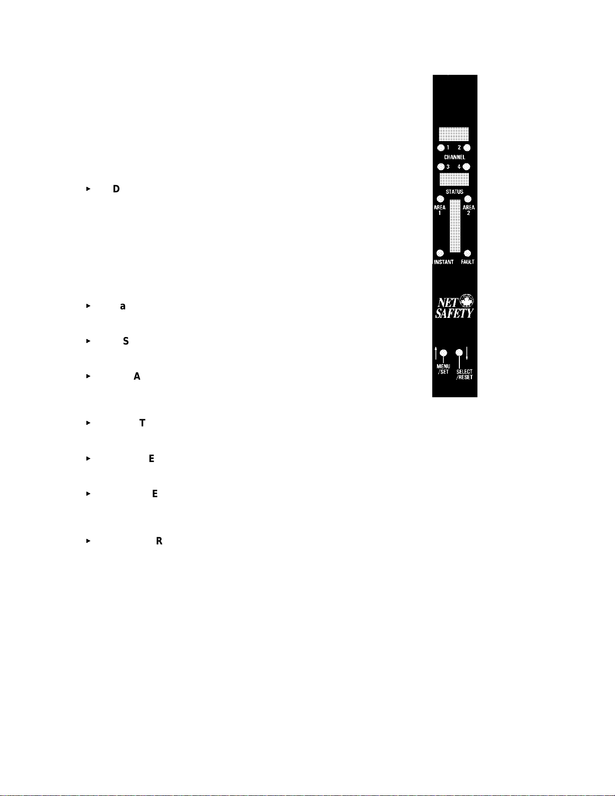
CONTRO LLER FACEPLATE DE S CRIPTIO N
The controller f ac eplate provides LEDs and two digit al displays f or
identifying status conditions, a bar gr aph display f or indicating an alarm
conditi on and MENU/SET and SELECT/RESET push-but ton switches
for testing and resetting the system. Refer to Figure 3.
<
Digital Displays - The upper digital display is normally off. If a
fir e alarm or visual integrity faul t is detected, it indi cates the
channel number of the alarm or fault. The digital displays
indicat e system status incl uding system error c odes, visual
integrity (vi) faults, system faults or fire alarms. T he lower
display shows ‘nor’ in normal oper ating mode. If more than
one channel is i n an alarm or fault condition the digital displays
will cycle through these channels. Since at least one di spl ay is
always lit they also function as a power indicat or .
<
Bar Graph Display - Norm ally off. F lashing when fir e
detected in any area.
<
INSTANT LED - (no time delay ) Flashes when any detector
signal exceeds the fir e sensit ivity setting.
<
AREA 1 & 2 LEDs - (Area 1 only for R1F) If the select ed
“voting” criteria of the area and the preset t ime del ay has
elapsed the corresponding LE D star ts flashing.
<
FAULT LED - flashes upon detection of an ov er all system fault
or vi fault.
<
CHANNEL LEDs - (1, 2 or 4 depending on model ) flash to i ndicate detect or in alarm
and remain illuminated until reset, after an alarm condition has ret ur ned to normal .
<
MENU/SET Push-button - is used to enter the m ain menu, t o toggle through menu
selections and i n c onjunction wit h the SELECT/RESET push-button to enter t he special
functions menu.
<
SELECT/RESET Pu sh-b u tton - is used for a basic system reset, m enu sel ec tion and
with the MENU/SET push-button to ent er the special functions m enu. This switch is
also used during the manual vi test.
OUTPUTS
Relay Outp uts:
The Instant, A rea and Fault relays have SP DT contacts rated 5 A mps at 30 Volts dc or 250
Volts ac.
The Instant and Area alarm relays are programmable for either normally energized or normally
de-energized operation and for latching or non- latching ( pr ogr ammabl e as a group not
individually). T he fault r elay is only nor mally ener gized. The relays can be configured with
jumpers for normally open or normally c losed contacts.
Figure 3 - Controller
Face-Plate
- 4 -
RECOMMENDATION
The fault relay output should not be used t o ac tivate an automatic s hutdown procedure.
The fault output indicates a potential problem with the c ontroller, not an alarm c ondition.
Refer to Table 1 for a sum mary of the relay programmi ng options.
Table 1 - Selectable O utput Options
OUTPUT
1
AREA
Selectable Normal ly
Open/Closed
YYY
Selectable Normal ly
Energized/De-Energized
Selectable
Latching/Non-Latching
INSTANT Y Y Y
FAULT Y N
1
2
3
Area alarms are programmed together, not indi vidually
Fault relay is normally energized
Fault relay is non-latching
2
3
N
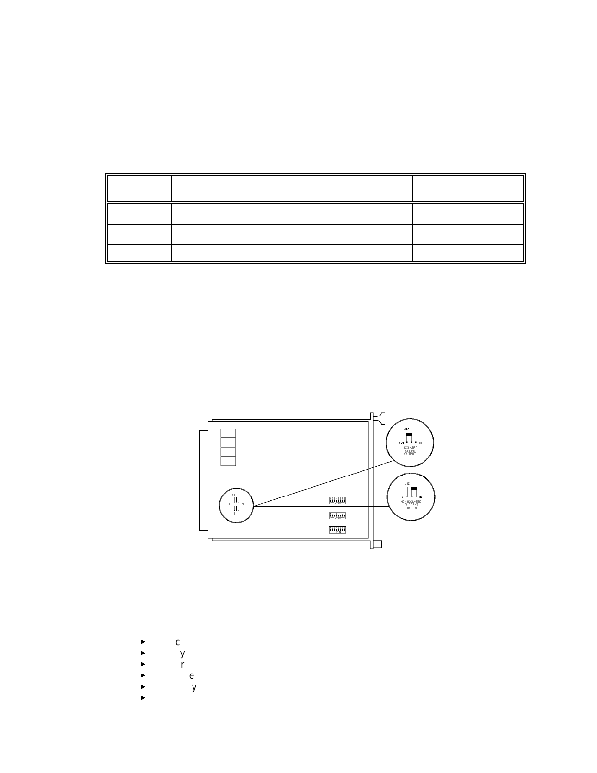
Current Outputs:
4-20 mA DC cur r ent outputs transmit system i nformation to other devices. The current out puts
can be wired for isolated or non-i sol ated operation by c hanging the jumpers as shown in
Figure 4. Refer to Unit IV, System Operation for a description of the c ur r ent output signal levels.
Figure 4 - Jumper Selections for an Isolated or Non-isolated Current
Output
PROGRAMMING OPTIONS
DIP switches locat ed on the circui t board are used to “program” var ious options including:
<
<
<
<
<
<
channel select ion,
system sensitivity,
fir e area vot ing logic,
tim e delay for fire area alarms,
relay latching/non-latching selec tion, and
relay energized/de-energiz ed sel ec tion.
- 5 -

NOTE
Power to the controller must be cycled to make dip switch changes take effect .
EXTERNAL RESET
A normal ly open, m omentary closure switch connected between the external reset terminal and
the negative power terminal provides remote reset.
AUTOMATI C DIAGNOSTI CS AND FAULT IDENT IFICATIO N
The mi croprocessor-based controller featur es self-testing c ircuit r y that continuously checks for
problems t hat could prevent proper system response. When power is appl ied, the
microprocessor automatically tests memory . In the Norm al Operating Mode it cont inuously
monit ors the system to ensure proper functioning. A "watchdog" t imer i s maintained to ensure
that the program is running c or r ec tly.
The mai n loop of the operating program continuously cycles through the Automati c Visual
Integrity test, check ing each detector and its wiring. The micr opr ocessor can be interrupted by
any one of several status changes such as a fault or a "fire" signal from one of the detection
areas to take appropriate action.
If a system or v i faul t is detected the Fault LED flashes, digi tal display s and curr ent outputs
identify the nat ur e of the fault and the fault relay is de-energi z ed.
VOTING LOGIC (not applicable to R1F)
The controller can be DIP switc h c onfigured for eit her one or two monitoring areas. For a one
area configuration, all channels are consi dered as being in Area 1 and both A r ea alarm relays
will be activated together.
The dip switches can be set so that only one channel need be i n alarm t o ac tivate the area alar m
or any two channels must ‘vote’ (see a fire at t he same time) to acti vate t he ar ea alarm. The
instant alarm will be activated when any channel sees UV radiation exceeding the preset
sensitivity setting, no m atter what voting option is being used.
For a two area configurati on, channel one (one and two f or R4F) make up A r ea 1 and c hannel
two (three and f our for R4F) make up Area 2. With the R4F each Area alarm m ay be
programmed with different voting criter ia (ie. Ar ea 1 may be set so that ei ther channel one OR
channel two may ac tivate the area alar m, and Area 2 may be set so that both channels three
AND four must see the fire at the same t ime to activate the Area al arm).
DETECTOR
The detector responds to UV radiation over the r ange of 185 to 260 nanometers. It is not
sensitive to direc t or reflected sunlight nor to normal artificial li ghting.
The detector is housed in an explosi on- pr oof enclosure t hat is designed to meet most national
and international standards. It is available in anodized aluminum or optional stainless steel.
The detector is typically mounted with a swivel mounting assembly which i s recommended.
Other m ounting arrangements are possible.
- 6 -

Unit II UV FIRE DETE CTIO N
SYSTEM APPLICATI ON
The detector responds instantly to ultraviolet r adiation emitted by a flame. It is designed for use
in hazardous locations and is suitable for use in outdoor applications.
Typical applications for UV detection system s are:
<
<
<
<
Petroleum Products Handling
<
<
<
<
<
<
Gaseous Fuel Handling
<
<
<
<
<
<
Other Processes
<
<
<
Automat ed fire pr otection system s al so have applications in any manufacturing or research
facility where the potential of fire may be low to moderate but the losses due to a f ire would be
high.
around highly combustible materials
if instantaneous response to fl ame is needed
where automated fire prot ec tion is required
to protect large capit al investments
petroleum loading t er minals
offshore platforms
pipeli ne st ations
tank far ms
refineries
engine rooms
butane and propane loadi ng and st or age
pipeli ne compressor stations
gas gathering facilities
LNG loading, transfer and stor age
hydrogen
gas turbines
paint spray booths
chemic al and petrochemical produc tion
powder coating booths
DETECTOR SENSIT IVITY
SPECTRAL SENSITIVITY RANGE
The UV fire detector r esponds to radiation wavelengths of 185 to 260 nanometers (1850 to 2600
angstroms). F igur e 5 illustrates the range of sensitivity and c ompares this range to other forms
of radi ation. Note that UV radiat ion reaching the ear th from the sun does not extend into the
sensitivity r ange of the detector. Nor does radiat ion from normal ar tif icial lighti ng, such as
fluor escent, mercur y vapor and i nc andescent lamps.
- 7 -
 Loading...