

Rosemount Manual: Rack-Mount Controller with IR Detection using IRC90-H HEAD | Rosemount Manuals & Guides

MODEL #: R1F, R2F & R4F-IR with IRC90H
INFRARED FIRE DETECTION SYSTEM
1, 2 and 4 Channel Rack Mount Controller
with IRC90H Detector
Part Number: MAN-0024-00 Rev 3

Copyright © 2002 Net Safety Monitoring Inc.
Printed in Canada
This manual is provided for informational purposes only. Although the information contained in this
manual is believed to be accurate, it could include technical inaccuracies or typographical errors.
Changes are, therefore, periodically made to the information within this document and
incorporated without notice into subsequent revisions of the manual. Net Safety Monitoring Inc.
assumes no responsibility for any errors that may be contained within this manual.
This manual is a guide for the use of a 1, 2 and 4 Channel Rack Mount Controller and the data
and procedures contained within this document have been verified and are believed to be
adequate for the intended use of the controller. If the controller or procedures are used for
purposes other than as described in the manual without receiving prior confirmation of validity or
suitability, Net Safety Monitoring Inc. does not guarantee the results and assumes no obligation or
liability.
No part of this manual may be copied, disseminated or distributed without the express written
consent of Net Safety Monitoring Inc.
Net Safety Monitoring Inc. products, are carefully designed and manufactured from high quality
components and can be expected to provide many years of trouble free service. Each product is
thoroughly tested, inspected and calibrated prior to shipment. Failures can occur which are
beyond the control of the manufacturer. Failures can be minimized by adhering to the operating
and maintenance instructions herein. Where the absolute greatest of reliability is required,
redundancy should be designed into the system.
Net Safety Monitoring Inc., warrants its sensors and detectors against defective parts and
workmanship for a period of 24 months from date of purchase and other electronic assemblies for
36 months from date of purchase.
No other warranties or liability, expressed or implied, will be honoured by Net Safety Monitoring
INC
Contact Net Safety Monitoring Inc. or an authorized distributor for details.


Table of Contents
Unit I GENERAL INFORMATION ................................... 1
DESCRIPTION................................................................ 1
FEATURES .................................................................. 1
CONTROLLER SPECIFICATIONS ................................................ 1
Figure 1 - Controller Dimensions............................................ 2
DETECTOR SPECIFICATIONS ................................................... 2
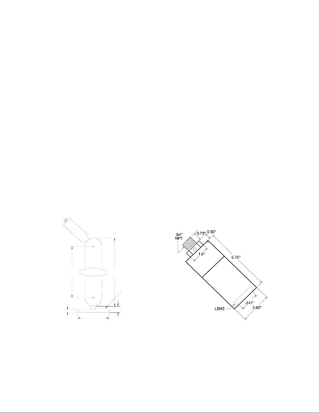
Figure 2a - Swivel Mount Dimension ......................................... 3
Figure 2b - Detector Dimensions............................................ 3
Figure 3 - Controller
Face-Plate ......................................................4
BASIC OPERATION - CONTROLLER .............................................. 4
CONTROLLER FACEPLATE DESCRIPTION .................................4
OUTPUTS ............................................................. 4
Table 1 - Selectable Output Options .........................................5
Figure 4 - Jumper Selections for Isolated or Non-isolated Current Outputs ........... 5
PROGRAMMING OPTIONS ...............................................5
EXTERNAL RESET ..................................................... 6
AUTOMATIC DIAGNOSTICS AND FAULT IDENTIFICATION..................... 6
VOTING LOGIC (not applicable to R1F) ...................................... 6
DETECTOR ..................................................................6
Unit II IR FIRE DETECTION ....................................... 7
SYSTEM APPLICATION ........................................................ 7
DETECTOR SENSITIVITY....................................................... 7
SPECTRAL SENSITIVITY RANGE ......................................... 7
CONE OF VISION ....................................................... 8
Figure 6 - Detector Cone of Vision .......................................... 8
SYSTEM SENSITIVITY ......................................................... 8
Unit III SYSTEM INSTALLATION ................................... 8
INSTALLATION ............................................................... 8
GENERAL WIRING REQUIREMENTS....................................... 8
CONTROLLER WIRING .................................................. 9
Figure 7a - Wiring for R1F - IR with Non-Isolated Current Output ................. 10
Figure 7b - Wiring for R1F - IR with Isolated Current Output ..................... 11
Figure 8a - Wiring for R2F - IR with Non-Isolated Current Output ................. 12
Figure 8b - Wiring for R2F - IR with Isolated Current Output ..................... 12
Figure 9a - Wiring for R4F - IR with Non-Isolated Current Output ................. 13
Figure 9b - Wiring for R4F - IR with Isolated Current Output ..................... 14
POSITION AND DENSITY OF DETECTORS ....................................... 16
MOUNTING THE DETECTOR ............................................ 16
Figure 10 - Detector with Swivel Mount Assembly ............................. 16
DIP SWITCH SETTINGS ....................................................... 16
Figure 11a - Relay and Dip Switch Positions ................................. 16
Figure 11b - Dip Switch Operation ......................................... 16
CHANNEL SELECTION ................................................. 17
CONTROLLER SENSITIVITY ADJUSTMENT ................................17
FIRE AREA VOTING SEQUENCE (not applicable to R1F) ...................... 18
RELAY OUTPUTS LATCHING/NON-LATCHING.............................. 18
RELAY OUTPUTS ENERGIZED/DE-ENERGIZED ............................ 18
TIME DELAY FOR AREA ALARMS ........................................19
RELAY SETTINGS............................................................ 19
Figure 11c - Relay Settings............................................... 19
Unit IV SYSTEM OPERATION .................................... 19
SYSTEM OPERATION ........................................................ 19

STARTUP PROCEDURE ............................................... 19
CHECKOUT PROCEDURE .............................................. 20
MANUAL vi CHECK/COUNT TEST ........................................ 20
MANUAL CHECK PROCEDURE .......................................... 21
ALTERNATE TEST PROCEDURE ........................................ 21
NORMAL OPERATION........................................................ 21
FIRE RESPONSE ..................................................... 21
Table 2 - Current Outputs................................................ 22
AUTOMATIC DIAGNOSTICS AND FAULT IDENTIFICATION ................... 22
Table 3 - Error Codes ................................................... 23
MAIN MENU ................................................................ 23
ERROR CHECK MODE (Err Chc) ......................................... 24
BYPASS MODE (bPS) .................................................. 24
SPECIAL FUNCTION MENU ................................................... 24
FORCED CURRENT OUTPUT MODE (FoP) ................................ 24
CURRENT CALIBRATION MODE (CuC) ................................... 25
ADDRESS SET MODE (do not use) ....................................... 25
Unit V MAINTENANCE .......................................... 25
ROUTINE MAINTENANCE ..................................................... 25
TROUBLESHOOTING ........................................................ 26
DEVICE REPAIR AND RETURN ................................................ 26
Appendix A Net Safety Monitoring Inc. Electrostatic Sensitive Device
Handling Procedure ............................................ 27
Appendix B Record Of Dip Switch Settings ........................ 28
Appendix C Wire Resistance In Ohms ............................. 29

Unit I GENERAL INFORMATION
DESCRIPTION
The IRC90H Flame Detector combined with the R1F, R2F or R4F-IR fire controller provide fast,
reliable flame detection in a wide variety of applications. The microprocessor based controllers
simultaneously monitor up to four infrared (IR) detectors to provide maximum operating flexibility
at minimum expense. The Automatic Visual Integrity (vi) feature provides a continuous check of
optical surfaces, sensitivity and electronic circuitry of the detector. Automatic fault identification
monitors system operation and provides a digital display of system status using a numerical code.
Controller response includes actuation of relays for direct control of field response devices and a
full array of faceplate indicators. Other features include individual channel and area identification,
"voting" capability and manual vi testing.
FEATURES
< Instantaneous response to infrared radiation
< Automatic and manual visual integrity (vi) testing
< Adjustable sensitivity and time delay
< All automatic test functions performed with the system on line
< Automatic fault identification
< Individual channel identification with voting options
< Latching area LEDs identify the area responding to fire
< Micro-processor based controller is easily field-programmable
< Two digital displays, one bar graph display and high intensity LEDs indicate
system status information
< Relay outputs are field adjustable as latching or non-latching
< Alarm relays are programmable for normally energized or de-energized operation
< Individual detector output (count rate) can be visually monitored on the digital
display
< Two 4-20mA current outputs (R2F and R4F). One 4-20mA output on R1F
< Conduit seals recommended to prevent moisture damage but not required
CONTROLLER SPECIFICATIONS
< Operating Voltage:
24Vdc nominal. 18 to 32Vdc.
< Power Consumption (controller only):
2.4 Watts nominal, 4.4 Watts maximum
100 mA nominal, 180 mA maximum at 24 Volts DC
Maximum startup current is 1.5 Amperes for 10 milliseconds. Power supplies with
fold back current limiting are not recommended.
< Maximum Ripple:
Ripple should not exceed 5 Volts peak-to-peak. The sum of DC plus ripple must
$18 Vdc and #32 Vdc
be
< Temperature Range:
Operating: -40ºC to +85ºC (-40ºF to +185ºF)
Storage: -55ºC to +150ºC (-65ºF to +302ºF)
- 1 -

< Relay Contacts:
Normally open/normally closed contacts rated for 5 Amperes at 30 Volts DC/ 250
Volts AC
< Current Outputs:
4-20mA DC into a maximum external loop resistance of 600 Ohms at 18-32 Volts
DC
< Dimensions:
Refer to Figure 1
< Shipping Weight (approximate):
2 lbs (0.9 kilograms)
< Certification:
CSA certified for ordinary, non-hazardous general purpose locations
< System Sensitivity:
Sensitivity for the standard controller is field adjustable over a range of 2 through
30 unit counts in increments of 2 units. The maximum response distance is
achieved at a 2 unit sensitivity setting. For applications involving high background
radiation potential, the system can be de-sensitized by increasing the count rate
required to actuate alarms. The 30 unit setting is the lowest sensitivity.
< Response Time:
Response to a saturating (high intensity) IR source is typically 10 milliseconds for
the instant alarm outputs and 0.5 seconds for the area alarm outputs when
sensitivity is set for 2 units and time delay is set for 0.5 seconds (minimum
settings)
Figure 1 - Controller Dimensions
DETECTOR SPECIFICATIONS
< Operating Voltage:
24Vdc ± 3V
- 2 -
< Power Consumption (each detector):
1.45 Watts nominal, 2.9 Watts maximum
60mA nominal, 120mA maximum
< Temperature Range:
Operating: -40ºC to +125ºC (-40ºF to +257ºF)
Storage: -55ºC to +150ºC (-65ºF to +302ºF)
< Dimensions:
Refer to Figures 2a and 2b
< Detector Enclosure Materials:
Available in anodized copper-free aluminum or optional stainless steel
< Shipping Weight (approximate):
2 lbs (0.9 kilograms)
< Certification:
CSA, NRTL/C, NEMA 4X certified for hazardous locations
Class 1, Division 1, Groups B, C and D
IEC approval (Class 1, Zone 1 Groups IIB+H2 T5)
< Spectral Sensitivity Range:
The detector responds to IR radiation in the 4.4 micrometre range
< Cone of Vision:
The detector has a nominal 90 degree cone of vision
4.13"
0.25"
2.50"
5.50"
4, 1/4"
holes in
base for
mounting
0.5"
Figure 2a - Swivel Mount Dimension
Figure 2b - Detector Dimensions
- 3 -

BASIC OPERATION - CONTROLLER
CONTROLLER FACEPLATE DESCRIPTION
The controller faceplate provides LEDs and two digital displays for
identifying status conditions, a bar graph display for indicating an alarm
condition and MENU/SET and SELECT/RESET push-button switches for
testing and resetting the system. Refer to Figure 3.
< Digital Displays - The upper digital display is normally off.
If a fire alarm or visual integrity fault is detected, it indicates
the channel number of the alarm or fault. The digital
displays indicate system status including system error
codes, visual integrity (vi) faults, system faults or fire
alarms. The lower display shows ‘nor’ in normal operating
mode. If more than one channel is in an alarm or fault
condition the digital displays will cycle through these
channels. Since at least one display is always lit they also
function as a power indicator.
< Bar Graph Display - Normally off. Flashing when fire
detected in any area.
< INSTANT LED - (no time delay) Flashes when any
detector signal exceeds the fire sensitivity setting.
< AREA 1 & 2 LEDs - (Area 1 only for R1F) If the selected
“voting” criteria of the area and the preset time delay has
elapsed the corresponding LED starts flashing.
< FAULT LED - Flashes upon detection of an overall system
fault or vi fault.
< CHANNEL LEDs - (1, 2, 3 or 4 depending on model) Flash to indicate detector in
alarm and remain illuminated until reset, after an alarm condition has returned to
normal.
< MENU/SET Push-button - is used to enter the main menu, to toggle through
menu selections and in conjunction with the SELECT/RESET push-button to
enter the special functions menu.
< SELECT/RESET Push-button - is used for a basic system reset, menu selection
and with the MENU/SET push-button to enter the special functions menu. This
switch is also used during the manual vi test.
OUTPUTS
Relay Outputs:
The instant, area and fault relays have SPDT contacts rated 5A at 30 Volts dc or 250 Volts ac.
The instant and area alarm relays are programmable for either normally energized or normally deenergized operation and for latching or non-latching (programmable as a group not individually).
The fault relay is only normally energized. The relays can be configured with jumpers for normally
open or normally closed contacts.
Figure 3 - Controller
Face-Plate
- 4 -
RECOMMENDATION
The fault relay output should not be used to activate an automatic shutdown procedure.
The fault output indicates a potential problem with the controller, not an alarm condition.
Refer to Table 1 for a summary of the relay programming options.
Table 1 - Selectable Output Options
OUTPUT
1
AREA
Selectable Normally
Open/Closed
YYY
Selectable Normally
Energized/De-Energized
Selectable
Latching/Non-Latching
INSTANT Y Y Y
FAULT Y N
1
2
3
Area alarms are programmed together, not individually
Fault relay is no rmally energized
Fault relay is non-latching
2
3
N
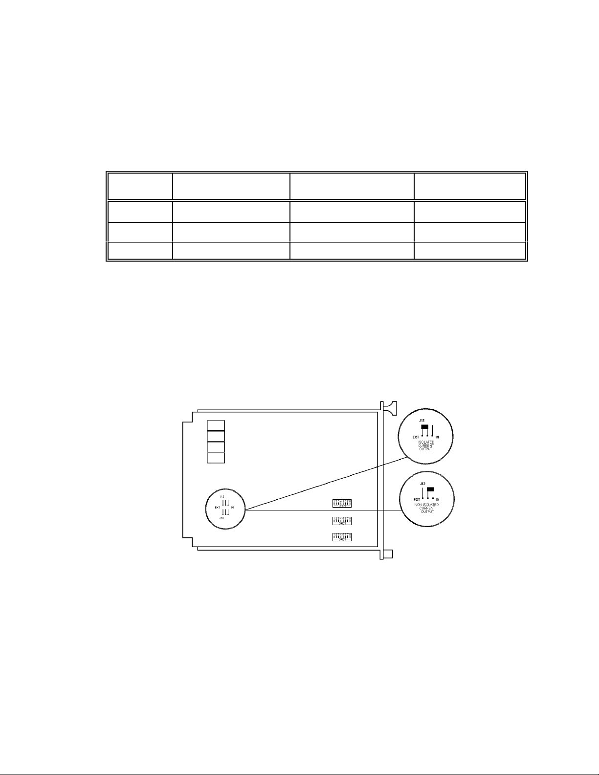
Current Outputs:
4-20 mA DC current outputs transmit system information to other devices. The current outputs can
be wired for isolated or non-isolated operation by changing the jumpers as shown in Figure 4.
Refer to Unit IV, System Operation for a description of the current output signal levels.
Figure 4 - Jumper Selections for Isolated or Non-isolated Current Outputs
PROGRAMMING OPTIONS
DIP switches located on the circuit board are used to “program” various options including:
< channel selection
< system sensitivity
< fire area voting logic
< time delay for fire area alarms
- 5 -

< relay latching/non-latching selection
< relay energized/de-energized selection
NOTE:
Power to the controller must be cycled OFF-ON to make dip switch changes take
effect.
EXTERNAL RESET
A normally open, momentary closure switch connected between the external reset terminal and
the negative power terminal provides remote reset.
AUTOMATIC DIAGNOSTICS AND FAULT IDENTIFICATION
The micro-processor based controller features self-testing circuitry that continuously checks for
problems that could prevent proper system response. When power is applied, the micro-processor
automatically tests memory. In the normal operating mode it continuously monitors the system to
ensure proper functioning. A "watchdog" timer is maintained to ensure that the program is running
correctly.
The main loop of the operating program continuously cycles through the automatic visual integrity
(vi) test, checking each detector and its wiring. The micro-processor can be interrupted by any
one of several status changes such as a fault or a "fire" signal from one of the detection areas to
take appropriate action.
If a system or vi fault is detected the fault LED flashes, digital displays and current outputs identify
the nature of the fault and the fault relay is de-energized.
VOTING LOGIC (not applicable to R1F)
The controller can be DIP switch configured for either one or two monitoring areas. For a one area
configuration, all channels are considered as being in Area 1 and both area alarm relays will be
activated together.
The dip switches can be set so that only one channel need be in alarm to activate the area alarm
or that any two channels must ‘vote’ (see a fire at the same time) to activate the area alarm. The
instant alarm will be activated when any channel sees IR radiation exceeding the preset sensitivity
setting, no matter what voting option is being used.
For a two area configuration, channel one (one and two for R4F) make up Area 1 and channel two
(three and four for R4F) make up Area 2. With the R4F, each area alarm may be programmed
with different voting criteria (ie. Area 1 may be set so that either channel one OR channel two may
activate the area alarm, and Area 2 may be set so that both channels three AND four must see
the fire at the same time to activate the area alarm).
DETECTOR
The detector responds to IR radiation in the 4.4 micrometre range. It is insensitive to direct or
reflected sunlight, arc welding, lightning and other ultraviolet producing phenomena.
The detector is housed in an explosion-proof enclosure that is designed to meet most national and
international standards. It is available in anodized aluminum or optional stainless steel.
The detector is typically mounted with a swivel mounting assembly which is recommended. Other
mounting arrangements are possible.
- 6 -
 Loading...