

Manual: Oxymitter 5000 O2 Transmitter with FOUNDATION Fieldbus Communications-Rev 1.0 | Rosemount
Table of contents
 Loading...
Rosemount Manual: Oxymitter 5000 O2 Transmitter with FOUNDATION Fieldbus Communications-Rev 1.0 | Rosemount Manuals & Guides

OXYMITTER 5000
OXYGEN TRANSMITTER
WITH FOUNDATION
FIELDBUS COMMUNICATIONS
Instruction Bulletin IB-106-350 Revision 1.0
Oxymitter 5000
Part no. _______________
Serial no. _______________
Order no. _______________
Cal Recommended
Autocal
F fieldbus
OUNDATION
STAY OFF THE STACK!
28550032

HIGHLIGHTS OF CHANGES
Effective March, 1999 Rev. 1.0
PAGE SUMMARY
3-1 Added note referencing appendices for fieldbus information.
A-5 Added Table A-4.
A-6 Added Table A-5.
IB-106-350

OXYMITTER 5000
OXYGEN TRANSMITTER
WITH FOUNDATION
FIELDBUS COMMUNICATIONS
NOTICE
Read this manual before working with the product. For personal and system safety, and for optimum
product performance, make sure you thoroughly understand the contents before installing, using, or
maintaining this product.
The products described in this document are NOT designed for nuclear-qualified applications.
Using non-nuclear-qualified products in applications that require nuclear-qualified hardware or
products may cause inaccurate readings.
For information on Fisher-Rosemount nuclear-qualified products, contact your local FisherRosemount Sales Representative.
Rosemount is a registered trademark of Rosemount Inc.
Delta V, the Delta V logotype, PlantWeb, and the PlantWeb logotype are trademarks of Fisher-Rosemount.
OUNDATION
F
is a trademark of the Fieldbus Foundation.
Rosemount satisfies all obligations coming from legislation to harmonize the product requirements
in the European Union.

ROSEMOUNT WARRANTY
Rosemount warrants that the equipment manufactured and sold by it will, upon shipment, be free of defects in workmanship or material. Should any failure to conform to this
warranty become apparent during a peri od of on e year after the date of s h ipment, Rosemou n t
shall, upon prompt written notice from the purchaser, correct such nonconformity by repair
or replacement, F.O.B. factory of the defective part or parts. Correction in the manner
provided above shall constitute a fulfillment of all liabilities of Rosemount with respect to
the quality of the equipment.
THE FOREGOING WARRANTY IS EXCLUSIVE AND IN LIEU OF
ALL OTHER WARRANTIES OF QUALITY WHETHER WRITTEN, ORAL,
OR IMPLIED (INCLUDING ANY WARRANTY OF MERCHANTABILITY OF
FITNESS FOR PURPOSE).
The remedy(ies) provided above s h all be pu rch as er's sole remedy(ies ) f or an y failure of
Rosemount to comply with the warranty provisions, whether claims by the purchaser are
based in contract or in tort (including negligence).
Rosemount does not warrant equipment against normal deteriora tion due to environment. Factors such as corrosive gases and solid particulates can be detrimental and can
create the need for repair or replacement as part of normal wear and tear during the warranty
period.
Equipment supplied by Rosemount Analytical Inc. but not manufactured by it will be
subject to the same warran t y as is extended to Rosemoun t by the original manu f actu rer.
At the time of installation it is important that the required services are supplied to the
system and that the electronic controller is set up at least to the point where it is controlling
the sensor heater. This will ensure, that should there be a delay between installation and full
commissioning that the sensor being supplied with ac power and reference air will not be
subjected to component deterioration.
IB-106-350
i

PURPOSE
The purpose of this manual is to provide a comprehensive understanding of the Oxymitter 5000
components, functions, installation, and maintenance.
This manual is designed to provide information about the Oxymitter 5000. We recommend that you
thoroughly familiarize yourself with the Description and Installation sections before installing your transmitter.
The description presents the basic principles of the transmitter along with its performance characteristics
and components. The remaining sections contain detailed procedures and information necessary to install and
service the transmitter.
Before contacting Rosemount concerning any questions, first consult this manual. It describes most
situations encountered in your equipment’s operation and details necessary action.
DEFINITIONS
The following definitions apply to WARNINGS, CAUTIONS, and NOTES found throughout this
publication.
Highlights an operation or maintenance
procedure, practice, condition, statement,
etc. If not strictly observed, could result
in injury, death, or long-term health
hazards of personnel.
Highlights an essential operating procedure,
condition, or statemen t.
: EARTH (GROUND) TERMINAL
: PROTECTIVE CONDUCTOR TERMINAL
: RISK OF ELECTRICAL SHOCK
: WARNING: REFER TO INSTRUCTION BULLETIN
NOTE TO USERS
Highlights an operation or maintenance
procedure, practice, condition, statement,
etc. If not strictly observed, could result
in damage to or destruction of equipment,
or loss of effectiveness.
NOTE
The number in the low er rig h t corn er of each illu stration in th is pu blication is a manual illustration number.
It is not a part number, and is not related to the illustration in any technical manner.
IB-106-35
ii
IMPORTANT
SAFETY INSTRUCTIONS FOR THE WIRING AND
INSTALLATION OF THIS APPARATUS
The following safety instructions apply specifically to all EU member
states. They should be strictly adhered to in order to assure
compliance with the Low Voltage Directive. Non-EU states should
also comply with the following unless superseded by local or National
Standards.
1. Adequate earth connections shou ld be made to all earthing points, in tern al an d ex tern al, where provided.
2. After installation or troubleshooting, all safety covers and safety grounds must be replaced. The integrity
of all earth terminals must be maintained at all tim es.
3. Mains supply cords s h ou ld comply w it h t h e requ irements of IEC227 or IEC 245.
4. All wiring shall be su itable f or us e in an ambient temperature of greater than 75°C .
5. All cable glands used shou ld be of s u ch in tern al dimensions as to provide adequ ate cable an ch orag e.
6. To ensure safe operation of this equipment, connection to the mains supply should only be made through
a circuit breaker which will disconnect all circuits carrying conductors during a fault situation. The circuit
breaker may also include a mechanically operated isolating switch. If not, then another means of
disconnecting the equipment from the supply must be provided and clearly marked as such. Circuit
breakers or switches must comply with a recognized standard such as IEC947. All wiring must conform
with any local s tan dards.
7. Where equipment or covers are marked with the symbol to the right,
hazardous voltages are likely to be present beneath. These covers should only
be removed when power is removed from the equipment — and then only by
trained service personnel.
8. Where equipment or covers are mark ed with the symbol to the right, there is a
danger from hot surfaces beneath. These covers should only be removed by
trained service personnel when power is removed from the equipment.
Certain surfaces may remain hot to the touch .
9. Where equipment or covers are marked with the symbol to the right, refer to
the Operator Manual for instructions .
10. All graphical symbols used in this product are from one or more of the following standards: EN61010-1,
IEC417, and ISO3864.
IB-106-350
iii
BELANGRIJK
Veiligheidsvoorschriften voor de aansluiting en installatie van dit toestel.
De hierna volgende veiligheidsvoorschriften zijn vooral bedoeld voor de EU lidstaten. Hier moet aan
gehouden worden om de onderworpenheid aan de Laag Spannings Richtlijn (Low Voltage Directive) te
verzekeren. Niet EU staten zouden deze richtlijnen moeten volgen tenzij zij reeds achterhaald zouden zijn
door plaatselijke of nationale voorschriften.
1. Degelijke aardingsaansluitingen moeten gemaakt worden naar alle voorziene aardpunten, intern en extern.
2. Na installatie of controle moeten alle veiligheidsdeksels en -aardingen terug geplaatst worden. Ten alle tijde
moet de betrouwbaarheid van de aarding behouden blijven.
3. Voedingskabels moeten onderworpen zijn aan de IEC227 of de IEC245 voorschriften.
4. Alle bekabeling moet geschikt zijn voor het gebruik in omgevingstemperaturen, hoger dan 75°C.
5. Alle wartels moeten zo gedimensioneerd zijn dat een degelijke kabel bevestiging verzekerd is.
6. Om de veilige werking van dit toestel te verzekeren, moet de voeding door een stroomonderbreker gevoerd
worden (min 10A) welke alle draden van de voeding moet onderbreken. De stroomonderbreker mag een
mechanische schakelaar bevatten. Zoniet moet een andere mogelijkheid bestaan om de voedingsspanning
van het toestel te halen en ook duidelijk zo zijn aangegeven. Stroomonderbrekers of schakelaars moeten onderworpen zijn aan een erkende standaard zoals IEC947.
7. Waar toestellen of deksels aangegeven staan met het symbool is er meestal hoogspanning aanwezig. Deze deksels mogen enkel verwijderd worden nadat de
voedingsspanning werd afgelegd en enkel door getraind onderhoudspersoneel.
8. Waar toestellen of deksels aangegeven staan met het symbool is er gevaar
voor hete oppervlakken. Deze deksels mogen enkel verwijderd worden door
getraind onderhoudspersoneel nadat de voedingsspanning verwijderd werd. Sommige oppper-vlakken kunnen 45 minuten later nog steeds heet aanvoelen.
9. Waar toestellen of deksels aangegeven staan met het symbool gelieve het handboek te raadplegen.
10. Alle grafische symbolen gebruikt in dit produkt, zijn afkomstig uit een of meer van devolgende standaards:
EN61010-1, IEC417 en ISO3864.
IB-106-350
iv
VIGTIGT
Sikkerhedsinstruktion for tilslutning og installering af dette udstyr.
Følgende sikkerhedsinstruktioner gælder specifikt i alle EU-medlemslande. Instruktionerne skal nøje
følges for overholdelse af Lavsspændingsdirektivet og bør også følges i ikke EU-lande medmindre andet er
specificeret af lokale eller nationale standarder.
1. Passende jordforbindelser skal tilsluttes alle jordklemmer, interne og eksterne, hvor disse forefindes.
2. Efter installation eller fejlfinding skal alle sikkerhedsdæksler og jordforbindelser reetableres.
3. Forsyningskabler skal opfylde krav specificeret i IEC227 eller IEC245.
4. Alle ledningstilslutninger skal være konstrueret til omgivelsestemperatur højere end 75° C.
5. Alle benyttede kabelforskruninger skal have en intern dimension, så passende kabelaflastning kan etableres.
6. For opnåelse af sikker drift og betjening skal der skabes beskyttelse mod indirekte berøring gennem afbryder
(min. 10A), som vil afbryde alle kredsløb med elektriske ledere i fejlsitua-tion. Afbryderen skal indholde en
mekanisk betjent kontakt. Hvis ikke skal anden form for afbryder mellem forsyning og udstyr benyttes og
mærkes som sådan. Afbrydere eller kontakter skal overholde en kendt standard som IEC947.
7. Hvor udstyr eller dæksler er mærket med dette symbol, er farlige spændinger normalt
forekom-mende bagved. Disse dæksler bør kun afmonteres, når forsyningsspændingen
er frakoblet - og da kun af instrueret servicepersonale.
8. Hvor udstyr eller dæksler er mærket med dette symbol, forefindes meget varme overflader bagved. Disse dæksler bør kun afmonteres af instrueret servicepersonale, når
forsyningsspænding er frakoblet. Visse overflader vil stadig være for varme at berøre i
op til 45 minutter efter frakobling.
9. Hvor udstyr eller dæksler er mærket med dette symbol, se da i betjeningsmanual for
instruktion.
10. Alle benyttede grafiske symboler i dette udstyr findes i én eller flere af følgende standarder:- EN61010-1,
IEC417 & ISO3864.
IB-106-350
v

BELANGRIJK
Veiligheidsinstructies voor de bedrading en installatie van dit apparaat.
Voor alle EU lidstaten zijn de volgende veiligheidsinstructies van toepassing. Om aan de geldende richtlijnen voor laagspanning te voldoen dient men zich hieraan strikt te houden. Ook niet EU lidstaten dienen
zich aan het volgende te houden, tenzij de lokale wetgeving anders voorschrijft.
1. Alle voorziene interne- en externe aardaansluitingen dienen op adequate wijze aangesloten te worden.
2. Na installatie,onderhouds- of reparatie werkzaamheden dienen alle beschermdeksels /kappen en aardingen
om reden van veiligheid weer aangebracht te worden.
3. Voedingskabels dienen te voldoen aan de vereisten van de normen IEC 227 of IEC 245.
4. Alle bedrading dient geschikt te zijn voor gebruik bij een omgevings temperatuur boven 75°C.
5. Alle gebruikte kabelwartels dienen dusdanige inwendige afmetingen te hebben dat een adequate verankering
van de kabel wordt verkregen.
6. Om een veilige werking van de apparatuur te waarborgen dient de voeding uitsluitend plaats te vinden via
een meerpolige automatische zekering (min.10A) die
foutconditie optreedt. Deze automatische zekering mag ook voorzien zijn van een mechanisch bediende
schakelaar. Bij het ontbreken van deze voorziening dient een andere als zodanig duidelijk aangegeven mogelijkheid aanwezig te zijn om de spanning van de apparatuur af te schakelen. Zekeringen en schakelaars dienen te voldoen aan een erkende standaard zoals IEC 947.
alle
spanningvoerende geleiders verbreekt indien een
7. Waar de apparatuur of de beschermdeksels/kappen gemarkeerd zijn met het volgende
symbool, kunnen zich hieronder spanning voerende delen bevinden die gevaar op kunnen leveren. Deze beschermdeksels/kappen mogen uitsluitend verwijderd worden door
getraind personeel als de spanning is afgeschakeld.
8. Waar de apparatuur of de beschermdeksels/kappen gemarkeerd zijn met het volgende
symbool, kunnen zich hieronder hete oppervlakken of onderdelen bevinden. Bepaalde
delen kunnen mogelijk na 45 min. nog te heet zijn om aan te raken.
9. Waar de apparatuur of de beschermdeksels/kappen gemarkeerd zijn met het volgende
symbool, dient men de bedieningshandleiding te raadplegen.
10. Alle grafische symbolen gebruikt bij dit produkt zijn volgens een of meer van de volgende standaarden: EN
61010-1, IEC 417 & ISO 3864.
IB-106-350
vi
TÄRKEÄÄ
Turvallisuusohje, jota on noudatettava tämän laitteen asentamisessa ja kaapeloinnissa.
Seuraavat ohjeet pätevät erityisesti EU:n jäsenvaltioissa. Niitä täytyy ehdottomasti noudattaa jotta täytettäisiin EU:n matalajännitedirektiivin (Low Voltage Directive) yhteensopivuus. Myös EU:hun kuulumattomien valtioiden tulee nou-dattaa tätä ohjetta, elleivät kansalliset standardit estä sitä.
1. Riittävät maadoituskytkennät on tehtävä kaikkiin maadoituspisteisiin, sisäisiin ja ulkoisiin.
2. Asennuksen ja vianetsinnän jälkeen on kaikki suojat ja suojamaat asennettava takaisin pai-koilleen.
Maadoitusliittimen kunnollinen toiminta täytyy aina ylläpitää.
3. Jännitesyöttöjohtimien täytyy täyttää IEC227 ja IEC245 vaatimukset.
4. Kaikkien johdotuksien tulee toimia >75°C lämpötiloissa.
5. Kaikkien läpivientiholkkien sisähalkaisijan täytyy olla sellainen että kaapeli lukkiutuu kun-nolla kiinni.
6. Turvallisen toiminnan varmistamiseksi täytyy jännitesyöttö varustaa turvakytkimellä (min 10A), joka kytkee
irti kaikki jännitesyöttöjohtimet vikatilanteessa. Suojaan täytyy myös sisältyä mekaaninen erotuskytkin. Jos
ei, niin jännitesyöttö on pystyttävä katkaisemaan muilla keinoilla ja merkittävä siten että se tunnistetaan
sellaiseksi. Turvakytkimien tai kat-kaisimien täytyy täyttää IEC947 standardin vaatimukset näkyvyydestä.
7. Mikäli laite tai kosketussuoja on merkitty tällä merkillä on merkinnän takana tai
alla hengenvaarallisen suuruinen jännite. Suojaa ei saa poistaa jänniteen ollessa
kytkettynä laitteeseen ja poistamisen saa suorittaa vain alan asian-tuntija.
8. Mikäli laite tai kosketussuoja on merkitty tällä merkillä on merkinnän takana tai
alla kuuma pinta. Suojan saa poistaa vain alan asiantuntija kun jännite-syöttö on
katkaistu. Tällainen pinta voi säilyä kosketuskuumana jopa 45 mi-nuuttia.
9. Mikäli laite tai kosketussuoja on merkitty tällä merkillä katso lisäohjeita käyttöohjekirjasta
10. Kaikki tässä tuotteessa käytetyt graafiset symbolit ovat yhdestä tai useammasta seuraavis-ta standardeista:
EN61010-1, IEC417 & ISO3864.
IB-106-350
vii
IMPORTANT
Consignes de sécurité concernant le raccordement et l’installation de cet appareil.
Les consignes de sécurité ci-dessous s’adressent particulièrement à tous les états membres de la communauté européenne. Elles doivent être strictement appliquées afin de satisfaire aux directives concernant
la basse tension. Les états non membres de la communauté européenne doivent également appliquer ces
consignes sauf si elles sont en contradiction avec les standards locaux ou nationaux.
1. Un raccordement adéquat à la terre doit être effectuée à chaque borne de mise à la terre, interne et externe.
2. Après installation ou dépannage, tous les capots de protection et toutes les prises de terre doivent être remis
en place, toutes les prises de terre doivent être respectées en permanence.
3. Les câbles d’alimentation électrique doivent être conformes aux normes IEC227 ou IEC245
4. Tous les raccordements doivent pouvoir supporter une température ambiante supérieure à 75°C.
5. Tous les presse-étoupes utilisés doivent avoir un diamètre interne en rapport avec les câbles afin d’assurer
un serrage correct sur ces derniers.
6. Afin de garantir la sécurité du fonctionnement de cet appareil, le raccordement à l’alimentation électrique
doit être réalisé exclusivement au travers d’un disjoncteur (minimum 10A.) isolant tous les conducteurs en
cas d’anomalie. Ce disjoncteur doit également pouvoir être actionné manuellement, de façon mécanique.
Dans le cas contraire, un autre système doit être mis en place afin de pouvoir isoler l’appareil et doit être
signalisé comme tel. Disjoncteurs et interrupteurs doivent être conformes à une norme reconnue telle
IEC947.
7. Lorsque les équipements ou les capots affichent le symbole suivant, cela signifie que
des tensions dangereuses sont présentes. Ces capots ne doivent être démontés que lorsque l’alimentation est coupée, et uniquement par un personnel compétent.
8. Lorsque les équipements ou les capots affichent le symbole suivant, cela signifie que
des surfaces dangereusement chaudes sont présentes. Ces capots ne doivent être
démontés que lorsque l’alimentation est coupée, et uniquement par un personnel compétent. Certaines surfaces peuvent rester chaudes jusqu’à 45 mn.
9. Lorsque les équipements ou les capots affichent le symbole suivant, se reporter au
manuel d’instructions.
10. Tous les symboles graphiques utilisés dans ce produit sont conformes à un ou plusieurs des standards suivants: EN61010-1, IEC417 & ISO3864.
IB-106-350
viii
Wichtig
Sicherheitshinweise für den Anschluß und die Installation dieser Geräte.
Die folgenden Sicherheitshinweise sind in allen Mitgliederstaaten der europäischen Gemeinschaft gültig.
Sie müssen strickt eingehalten werden, um der Niederspannungsrichtlinie zu genügen.
Nichtmitgliedsstaaten der europäischen Gemeinschaft sollten die national gültigen Normen und
Richtlinien einhalten.
1. Alle intern und extern vorgesehenen Erdungen der Geräte müssen ausgeführt werden.
2. Nach Installation, Reparatur oder sonstigen Eingriffen in das Gerät müssen alle Sicherheitsabdeckungen und
Erdungen wieder installiert werden. Die Funktion aller Erdverbindungen darf zu keinem Zeitpunkt gestört
sein.
3. Die Netzspannungsversorgung muß den Anforderungen der IEC227 oder IEC245 genügen.
4. Alle Verdrahtungen sollten mindestens bis 75 °C ihre Funktion dauerhaft erfüllen.
5. Alle Kabeldurchführungen und Kabelverschraubungen sollten in Ihrer Dimensionierung so gewählt werden,
daß diese eine sichere Verkabelung des Gerätes ermöglichen.
6. Um eine sichere Funktion des Gerätes zu gewährleisten, muß die Spannungsversorgung über mindestens 10
A abgesichert sein. Im Fehlerfall muß dadurch gewährleistet sein, daß die Spannungsversorgung zum Gerät
bzw. zu den Geräten unterbrochen wird. Ein mechanischer Schutzschalter kann in dieses System integriert
werden. Falls eine derartige Vorrichtung nicht vorhanden ist, muß eine andere Möglichkeit zur Unterbrechung der Spannungszufuhr gewährleistet werden mit Hinweisen deutlich gekennzeichnet werden. Ein solcher Mechanismus zur Spannungsunterbrechung muß mit den Normen und Richtlinien für die allgemeine
Installation von Elektrogeräten, wie zum Beispiel der IEC947, übereinstimmen.
7. Mit dem Symbol sind Geräte oder Abdeckungen gekennzeichnet, die eine gefährliche (Netzspannung) Spannung führen. Die Abdeckungen dürfen nur entfernt
werden, wenn die Versorgungsspannung unterbrochen wurde. Nur geschultes Personal darf an diesen Geräten Arbeiten ausführen.
8. Mit dem Symbol sind Geräte oder Abdeckungen gekennzeichnet, in bzw. unter
denen heiße Teile vorhanden sind. Die Abdeckungen dürfen nur entfernt werden,
wenn die Versorgungsspannung unterbrochen wurde. Nur geschultes Personal
darf an diesen Geräten Arbeiten ausführen. Bis 45 Minuten nach dem Unterbrechen der Netzzufuhr können derartig Teile
noch über eine erhöhte Temperatur verfügen.
9. Mit dem Symbol sind Geräte oder Abdeckungen gekennzeichnet, bei denen vor
dem Eingriff die entsprechenden Kapitel im Handbuch sorgfältig durchgelesen
werden müssen.
10. Alle in diesem Gerät verwendeten graphischen Symbole entspringen einem oder mehreren der nachfolgend
aufgeführten Standards: EN61010-1, IEC417 & ISO3864.
IB-106-350
ix

IMPORTANTE
Norme di sicurezza per il cablaggio e l’installazione dello strumento.
Le seguenti norme di sicurezza si applicano specificatamente agli stati membri dell’Unione Europea, la cui
stretta osservanza è richiesta per garantire conformità alla Direttiva del Basso Voltaggio. Esse si applicano
anche agli stati non appartenenti all’Unione Europea, salvo quanto disposto dalle vigenti normative l ocali
o nazionali
1. Collegamenti di terra idonei devono essere eseguiti per tutti i punti di messa a terra interni ed esterni, dove
2. Dopo l’installazione o la localizzazione dei guasti, assicurarsi che tutti i coperchi di protezione siano stati
3. I cavi di alimentazione della rete devono essere secondo disposizioni IEC227 o IEC245.
4. L’intero impianto elettrico deve essere adatto per uso in ambiente con temperature superiore a 75°C.
5. Le dimensioni di tutti i connettori dei cavi utilizzati devono essere tali da consentire un adeguato ancoraggio
.
previsti.
collocati e le messa a terra siano collegate. L’integrità di ciscun morsetto di terra deve essere costantemente
garantita.
al cavo.
6. Per garantire un sicuro funzionamento dello strumento il collegamento alla rete di alimentazione principale
dovrà essere eseguita tramite interruttore automatico (min.10A), in grado di disattivare tutti i conduttori di
circuito in caso di guasto. Tale interruttore dovrà inoltre prevedere un sezionatore manuale o altro dispositivo di interruzione dell’alimentazione, chiaramente identificabile. Gli interruttori dovranno essere conformi
agli standard riconosciuti, quali IEC947.
7. Il simbolo riportato sullo strumento o sui coperchi di protezione indica probabile
presenza di elevati voltaggi. Tali coperchi di protezione devono essere rimossi esclusivamente da personale qualificato, dopo aver tolto alimentazione allo strumento.
8. Il simbolo riportato sullo strumento o sui coperchi di protezione indica rischio di
contatto con superfici ad alta temperatura. Tali coperchi di protezione devono essere
rimossi esclusivamente da personale qualificato, dopo aver tolto alimentazione allo
strumento. Alcune superfici possono mantenere temperature elevate per oltre 45 minuti.
9. Se lo strumento o il coperchio di protezione riportano il simbolo, fare riferimento alle istruzioni del manuale Operatore.
10. Tutti i simboli grafici utilizzati in questo prodotto sono previsti da uno o più dei seguenti standard:
EN61010-1, IEC417 e ISO3864.
IB-106-350
x

VIKTIG
Sikkerhetsinstruks for tilkobling og installasjon av dette utstyret.
Følgende sikkerhetsinstruksjoner gjelder spesifikt alle EU medlemsland og land med i EØS-avtalen.
Instruksjonene skal følges nøye slik at installasjonen blir i henhold til lavspenningsdirektivet. Den bør
også følges i andre land, med mindre annet er spesifisert av lokale- eller nasjonale standarder.
1. Passende jordforbindelser må tilkobles alle jordingspunkter, interne og eksterne hvor disse forefinnes.
2. Etter installasjon eller feilsøking skal alle sikkerhetsdeksler og jordforbindelser reetableres. Jordingsforbindelsene må alltid holdes i god stand.
3. Kabler fra spenningsforsyning skal oppfylle kravene spesifisert i IEC227 eller IEC245.
4. Alle ledningsforbindelser skal være konstruert for en omgivelsestemperatur høyere en 750C.
5. Alle kabelforskruvninger som benyttes skal ha en indre dimensjon slik at tilstrekkelig avlastning oppnåes.
6. For å oppnå sikker drift og betjening skal forbindelsen til spenningsforsyningen bare skje gjennom en
strømbryter (minimum 10A) som vil bryte spenningsforsyningen til alle elektriske kretser ved en feilsituasjon. Strømbryteren kan også inneholde en mekanisk operert bryter for å isolere instrumentet fra spenningsforsyningen. Dersom det ikke er en mekanisk operert bryter installert, må det være en annen måte å
isolere utstyret fra spenningsforsyningen, og denne måten må være tydelig merket. Kretsbrytere eller kontakter skal oppfylle kravene i en annerkjent standard av typen IEC947 eller tilsvarende.
7. Der hvor utstyr eller deksler er merket med symbol for farlig spenning, er det sannsynlig at disse er tilstede bak dekslet. Disse dekslene må bare fjærnes når spenningsforsyning er frakoblet utstyret, og da bare av trenet servicepersonell.
8. Der hvor utstyr eller deksler er merket med symbol for meget varm overflate, er det
sannsynlig at disse er tilstede bak dekslet. Disse dekslene må bare fjærnes når spenningsforsyning er frakoblet utstyret, og da bare av trenet servicepersonell. Noen overflater kan være for varme til å berøres i opp til 45 minutter etter spenningsforsyning
frakoblet.
9. Der hvor utstyret eller deksler er merket med symbol, vennligst referer til instruksjonsmanualen for instrukser.
10. Alle grafiske symboler brukt i dette produktet er fra en eller flere av følgende standarder: EN61010-1,
IEC417 & ISO3864.
IB-106-350
xi
IMPORTANTE
Instruções de segurança para ligação e instalação deste aparelho.
As seguintes instruções de segurança aplicam-se especificamente a todos os estados membros da UE. Devem ser observadas rigidamente por forma a garantir o cumprimento da Directiva sobre Baixa Tensão.
Relativamente aos estados que não pertençam à UE, deverão cumprir igualmente a referida directiva,
exceptuando os casos em que a legislação local a tiver substituído.
1. Devem ser feitas ligações de terra apropriadas a todos os pontos de terra, internos ou externos.
2. Após a instalação ou eventual reparação, devem ser recolocadas todas as tampas de seg urança e terras de
protecção. Deve manter-se sempre a integridade de todos os terminais de terra.
3. Os cabos de alimentação eléctrica devem obedecer às exigências das normas IEC227 ou IEC245.
4. Os cabos e fios utilizados nas ligações eléctricas devem ser adequados para utilização a uma temperatura
ambiente até 75º C.
5. As dimensões internas dos bucins dos cabos devem ser adequadas a uma boa fixação dos cabos.
6. Para assegurar um funcionamento seguro deste equipamento, a ligação ao cabo de alimentação eléctrica
deve ser feita através de um disjuntor (min. 10A) que desligará todos os condutores de circuitos durante uma
avaria. O disjuntor poderá também conter um interruptor de isolamento accionado manualmente. Caso
contrário, deverá ser instalado qualquer outro meio para desligar o equipamento da energia eléctrica, devendo ser assinalado convenientemente. Os disjuntores ou interruptores devem obedecer a uma norma reconhecida, tipo IEC947.
7. Sempre que o equipamento ou as tampas contiverem o símbolo, é provável a existência de tensões perigosas. Estas tampas só devem ser retiradas quando a energia
eléctrica tiver sido desligada e por Pessoal da Assistência devidamente treinado.
8. Sempre que o equipamento ou as tampas contiverem o símbolo, há perigo de existência de superfícies quentes. Estas tampas só devem ser retiradas por Pessoal da Assistência devidamente treinado e depois de a energia eléctrica ter sido desligada.
Algumas superfícies permanecem quentes até 45 minutos depois.
9. Sempre que o equipamento ou as tampas contiverem o símbolo, o Manual de Funcionamento deve ser consultado para obtenção das necessárias instruções.
10. Todos os símbolos gráficos utilizados neste produto baseiam-se em uma ou mais das seguintes normas:
EN61010-1, IEC417 e ISO3864.
IB-106-350
xii
IMPORTANTE
Instrucciones de seguridad para el montaje y cableado de este aparato.
Las siguientes instrucciones de seguridad , son de aplicacion especifica a todos los miembros de la UE y se
adjuntaran para cumplir la normativa europea de baja tension.
1. Se deben preveer conexiones a tierra del equipo, tanto externa como internamente, en aquellos terminales
previstos al efecto.
2. Una vez finalizada las operaciones de mantenimiento del equipo, se deben volver a colocar las cubiertas de
seguridad aasi como los terminales de tierra. Se debe comprobar la integridad de cada terminal.
3. Los cables de alimentacion electrica cumpliran con las normas IEC 227 o IEC 245.
4. Todo el cableado sera adecuado para una temperatura ambiental de 75ºC.
5. Todos los prensaestopas seran adecuados para una fijacion adecuada de los cables.
6. Para un manejo seguro del equipo, la alimentacion electrica se realizara a traves de un interruptor magnetotermico ( min 10 A ), el cual desconectara la alimentacion electrica al equipo en todas sus fases durante un
fallo. Los interruptores estaran de acuerdo a la norma IEC 947 u otra de reconocido prestigio.
7. Cuando las tapas o el equipo lleve impreso el simbolo de tension electrica peligrosa, dicho alojamiento solamente se abrira una vez que se haya interrumpido la
alimentacion electrica al equipo asimismo la intervencion sera llevada a cabo por
personal entrenado para estas labores.
8. Cuando las tapas o el equipo lleve impreso el simbolo, hay superficies con alta
temperatura, por tanto se abrira una vez que se haya interrumpido la alimentacion
electrica al equipo por personal entrenado para estas labores, y al menos se esperara unos 45 minutos para enfriar las superficies calientes.
9. Cuando el equipo o la tapa lleve impreso el simbolo, se consultara el manual de
instrucciones.
10. Todos los simbolos graficos usados en esta hoja, estan de acuerdo a las siguientes normas EN61010-1,
IEC417 & ISO 3864.
IB-106-350
xiii
VIKTIGT
Säkerhetsföreskrifter för kablage och installation av denna apparat.
Följande säkerhetsföreskrifter är tillämpliga för samtliga EU-medlemsländer. De skall följas i varje avseende för att överensstämma med Lågspännings direktivet. Icke EU medlemsländer skall också följa
nedanstående punkter, såvida de inte övergrips av lokala eller nationella föreskrifter.
1. Tillämplig jordkontakt skall utföras till alla jordade punkter, såväl internt som externt där så erfordras.
2. Efter installation eller felsökning skall samtliga säkerhetshöljen och säkerhetsjord återplaceras. Samtliga
jordterminaler måste hållas obrutna hela tiden.
3. Matningsspänningens kabel måste överensstämma med föreskrifterna i IEC227 eller IEC245.
4. Allt kablage skall vara lämpligt för användning i en omgivningstemperatur högre än 75ºC.
5. Alla kabelförskruvningar som används skall ha inre dimensioner som motsvarar adekvat kabelförankring.
6. För att säkerställa säker drift av denna utrustning skall anslutning till huvudströmmen endast göras genom en
säkring (min 10A) som skall frånkoppla alla strömförande kretsar när något fel uppstår. Säkringen kan även
ha en mekanisk frånskiljare. Om så inte är fallet, måste ett annat förfarande för att frånskilja utrustningen
från strömförsörjning tillhandahållas och klart framgå genom markering. Säkring eller omkopplare måste
överensstämma med en gällande standard såsom t ex IEC947.
7. Där utrustning eller hölje är markerad med vidstående symbol föreliggerisk för
livsfarlig spänning i närheten. Dessa höljen får endast avlägsnas när strömmen ej är
ansluten till utrustningen - och då endast av utbildad servicepersonal.
8. När utrustning eller hölje är markerad med vidstående symbol föreligger risk för
brännskada vid kontakt med uppvärmd yta. Dessa höljen får endast avlägsnas av utbildad servicepersonal, när strömmen kopplats från utrustningen. Vissa ytor kan vara
mycket varma att vidröra även upp till 45 minuter efter avstängning av strömmen.
9. När utrustning eller hölje markerats med vidstående symbol bör instruktionsmanualen
studeras för information.
10.
Samtliga grafiska symboler som förekommer i denna produkt finns angivna i en eller flera av följande
föreskrifter:- EN61010-1, IEC417 & ISO3864.
IB-106-350
xiv

IB-106-350
xv

CERAMIC FIBER PRODUCTS
MATERIAL SAFETY DATA SHEET
JULY 1, 1996
SECTION I. IDENTIFICATION
PRODUCT NAME
Ceramic Fiber Heaters, Molded Insulation Modules and Ceramic Fiber Radiant Heater Panels.
CHEMICAL FAMILY
Vitreous Aluminosilicate Fibers with Silicon Dioxide.
CHEMICAL NAME
N.A.
CHEMICAL FORMULA
N.A.
MANUFACTURER’S NAME AND ADDRESS
Watlow Columbia 573-474-9402
2101 Pennsylvania Drive 573-814-1300, ext. 5170
Columbia, MO 65202
HEALTH HAZARD SUMMARY
WARNING
• Possible cancer hazard based on tests with laboratory animals.
• May be irritating to skin, eyes and respiratory tract.
• May be harmful if inhaled.
• Cristobalite (crystalline silica) formed at high temperatures (above 1800ºF) can cause severe respiratory disease.
IB-106-350
xvi

SECTION II. PHYSICAL DATA
APPEARANCE AND ODOR
Cream to white colored fiber shapes. With or without optional white to gray granular surface coating and/or optional
black surface coating.
SPECIFIC WEIGHT: 12-25 lb./cubic foot BOILING POINT: N.A.
VOLATILES (% BY WT.): N.A. WATER SOLUBILITY: N.A.
SECTION III. HAZARDOUS INGREDIENTS
MATERIAL, QUANTITY, AND THRESHOLD/EXPOSURE LIMIT VALUES
Aluminosilicate (vitreous) 99+ % 1 fiber/cc TWA
CAS. No. 142844-00-06 10 fibers/cc CL
Zirconium Silicate 0-10% 5 mg/cubic meter (TLV)
Black Surface Coating** 0 - 1% 5 mg/cubic meter (TLV)
Armorphous Silica/Silicon Dioxide 0-10% 20 mppcf (6 mg/cubic meter)
**Composition is a trade secret.
PEL (OSHA 1978) 3 gm cubic meter
(Respirable dust): 10 mg/cubic meter,
Intended TLV (ACGIH 1984-85)
SECTION IV. FIRE AND EXPLOSION DATA
FLASH POINT: None FLAMMABILITY LIMITS: N.A.
EXTINGUISHING MEDIA
Use extinguishing agent suitable for type of surrounding fire.
UNUSUAL FIRE AND EXPLOSION HAZARDS/SPECIAL FIRE FIGHTING
PROCEDURES
N.A.
IB-106-350
xvii

SECTION V. HEALTH HAZARD DATA
THRESHOLD LIMIT VALUE
(See Section III)
EFFECTS OF OVER EXPOSURE
EYE
Avoid contact with eyes. Slightly to moderately irritating. Abrasive action may cause damage to outer surface of eye.
INHALATION
May cause respiratory tract irritation. Repeated or prolonged breathing of particles of respirable size may cause inflammation of the lung leading to chest pain, difficult breathing, coughing and possible fibrotic change in the lung
(Pneumoconiosis). Pre-existing medical conditions may be aggravated by exposure: specifically, bronchial hyperreactivity and chronic bronc hia l or lung disease.
INGESTION
May cause gastrointestinal disturbances. Symptoms may include irritation and nausea, vomiting and diarrhea.
SKIN
Slightly to moderate irritating. May cause irritation and inflammation due to mechanical reaction to sharp, broken ends
of fibers.
EXPOSURE TO USED CERAMIC FIBER PRODUCT
Product which has been in service at elevated temperatures (greater than 1800ºF/982ºC) may undergo partial conversion
to cristobalite, a form of crystalline silica which can cause severe respiratory disease (Pneumoconiosis). The amount of
cristobalite present will depend on the temperature and length of time in service. (See Section IX for permissible exposure levels).
SPECIAL TOXIC EFFECTS
The existing toxicology and epidemiology data bases for RCF’s are still preliminary. Information will be updated as
studies are completed and reviewed. The following is a review of the results to date:
EPIDEMIOLOGY
At this time there are no known published reports demonstrating negative health outcomes of workers exposed to refractory ceramic fiber (RCF). Epidemiologic investigations of RCF production workers are ongoing.
1) There is no evidence of any fibrotic lung disease (interstitial fibrosis) whatsoever on x-ray.
2) There is no evide nce of any lung disease among those employees exposed to RCF that had never smoked.
3) A statistical “trend” was observed in the exposed population between the duration of exposure to RCF and a
decrease in some measures of pulmonary function. These observations are clinically insignificant. In other words, if
these observations were made on an individual employee, the results would be interpreted as being within the normal
range.
4) Pleural plaques (thickening along the chest wall) have been observed in a small number of employees who had a
long duration of employment. There are several occupational and non-occupational causes for pleural plaque. It
should be noted that plaques are not “pre-cancer” nor are they associated with any measurable effect on lung
function.
IB-106-350
xviii

TOXICOLOGY
A number of studies on the health effects of inhalation exposure of rats and hamsters are available. Rats were exposed
to RCF in a series of life-time nose-only inhalation studies. The animals were exposed to 30, 16, 9, and 3 mg/m
corresponds with approximately 200, 150, 75, and 25 fibers/cc.
Animals exposed to 30 and 16 mg/m
posed to 9 mg/m
3
had developed a mild parenchymal fibrosis; animals exposed to the lowest dose were found to have
3
were observed to have developed a pleural and parenchymal fibroses; animals ex-
the response typically observed any time a material is inhaled into the deep lung. While a statistica lly significant increase in lung tumors was observed following exposure to the highest dose, there was no excess lung cancers at the other
doses. Two rats exposed to 30 mg/m
The International Agency for Research on Cancer (IARC) reviewed the carcinogenicity data on man-made vitreous fi-
3
and one rat exposed to 9 mg/m3 developed masotheliomas.
bers (including ceramic fiber, glasswool, rockwool, and slagwool) in 1987. IARC classified ceramic fiber, fibrous
glasswool and mineral wool (rockwool and slagwool) as possible human carcinogens (Group 2B).
EMERGENCY FIRST AID PROCEDURES
EYE CONTACT
Flush eyes immediately with large amounts of water for approximately 15 minutes. Eye lids should be held away from
the eyeball to insure thorough r insing. Do not rub eyes. Get medical attention if irritation persists.
INHALATION
Remove person from source of exposure and move to fresh air. Some people may be sensitive to fiber induced irritation
of the respiratory tract. If symptoms such as shortness of breath, coughing, wheezing or chest pain develop, seek medical attention. If person experiences continued breathing difficulties, administer oxygen until medical assistance can be
rendered.
3
, which
INGESTION
Do not induce vomiting. Get medical attention if irritation persists.
SKIN CONTACT
Do not rub or scra tch exposed skin. Wash area of contact thoroughly with soap and water. Using a skin cream or lotion
after washing may be helpful. Get medical attention if irritation persists.
SECTION VI. REACTIVITY DATA
STABILITY/CONDITIONS TO AVOID
Stable under normal conditions of use.
HAZARDOUS POLYMERIZATION/CONDITIONS TO AVOID
N.A.
IB-106-350
xix

INCOMPATIBILITY/MATERIALS TO AVOID
Incompatible with hydrofluoric acid and concentrated alkali.
HAZARDOUS DECOMPOSITION PRODUCTS
N.A.
SECTION VII. SPILL OR LEAK PROCEDURES
STEPS TO BE TAKEN IF MATERIAL IS RELEASED OR SPILLED
Where possible, use vacuum suction with HEPA filters to clean up spilled material. Use dust suppressant where sweeping if necessary. Avoid clean up procedure which may result in water pollution. (Observe Special Protection Information Section VIII.)
WASTE DISPOSAL METHODS
The transportation, treatment, and disposal of this waste material must be conducted in compliance with all applicable
Federal, State, and Local regulations.
SECTION VIII. SPECIAL PROTECTION INFORMATION
RESPIRATORY PROTECTION
Use NIOSH or MSHA approved equipment when airborne exposure limits may be exceeded. NIOSH/MSHA approved
breathing equipment may be required for non-routine and emergency use. (See Section IX for suitable equipment).
Pending the results of long term health effects studies, engineering control of airborne fibers to the lowest levels attainable is advised.
VENTILATION
Ventilation should be used whenever possible to control or reduce airborne concentrations of fiber and dust. Carbon
monoxide, carbon dioxide, oxides of nitrogen, reactive hydrocarbons and a small amount of formaldehyde may accompany binder burn-off during first heat. Use adequate ventilation or other precautions to eliminate vapors resulting from
binder burn-off. Exposure to burn-off fumes may cause respiratory tract irritation, bronchial hyper-reactivity and asthmatic response.
SKIN PROTECTION
Wear gloves, hats and full body clothing to prevent skin contact. Use separate lockers for work clothes to prevent fiber
transfer to street cl othes. Wash work clothes separ ately from other clothing and rinse washing machine thoro ughly after
use.
EYE PROTECTION
Wear safety glasses or chemical worker’s goggles to prevent eye contact. Do not wear contact lenses when working
with this substance. Have eye baths readily available where eye contact can occur.
IB-106-350
xx

SECTION IX. SPECIAL PRECAUTIONS
PRECAUTIONS TO BE TAKEN IN HANDLING AND STORING
General cleanliness should be followed.
The Toxicology data indicate that ceramic fiber should be handled with caution. T he handling practices described in this
MSDS must be strictly followed. In particular, when handling refractory ceramic fiber in any application, special caution should be taken to avoid unnecessary cutting and tearing of the material to minimize generation of airborne dust.
It is recommended that full body clothing be worn to reduce the potential for skin irritation. Washable or disposable
clothing may be used. Do not ta ke unwashed work clothing home. Work clothes should be washed separately from
other clothing. Rinse washing machine thor oughly after use. If clothing is to be launde red by someone else, inform
launderer of proper procedure. Work clothes and street clothes should be kept separate to prevent contamination.
Product which has been in service at elevated temperatures (greater than 1800ºF/982ºC) may undergo partial conversion
to cristobalite, a form of crystalline silica. This reaction occurs at the furnace lining hot face. As a consequence, this
material becomes more friable; special caution must be taken to minimize generation of airborne dust. The amount of
cristobalite present will depend on the temperature and length in service.
IARC has recently reviewed the animal, human, and other relevant experimental data on silica in order to critically
evaluate and classify the cancer causing potential. Based on its review, IARC classified crystalline silica as a group 2A
carcinogen ( probable human carcinogen).
The OSHA permissible exposure limit (PEL for cristobalite is 0.05 mg/m
value (TLV) for cristobalite is 0.05 mg/m
3
(respirable dust) (ACGIH 1991-92). Use NIOSH or MSHA approved
equipment when airborne exposure limits may be exceeded. The minimum respiratory protection recommended for
given airborne fiber or cristobalite concentrations are:
3
(respirable dust). The ACGIH threshold limit
CONCENTRATION
3
0-1 fiber/cc or 0-0.05 mg/m
(the OSHA PEL) 9970 or equivalent).
Up to 5 fibers/cc or up to 10 times the Half face, air-purifying respirator equipped
OSHA PEL for cristobalite with high efficiency particulate air (HEPA)
Up to 25 fibers/cc or 50 times the OSHA Full face, air-purifying respirator with high
PEL for cristobalite (2.5 mg/m
Greater than 25 fibers/cc or 50 times the Full face, positive pressure supplied air respiraOSHA PEL for cristobalite (2.5 mg/m
cristobalite Optional disposable dust respirator (e.g. 3M
filter cartridges (e.g. 3M 6000 series with
2040 filter or equivalent).
3
) efficiency particulate air (HEPA) filter cart-
ridges (e.g. 3M 7800S with 7255 filters or
equivalent) or powered air-purifying respirator
(PARR) equipped with HEPA filter cartridges
(e.g. 3M W3265S with W3267 filters or
equivalent).
3
) tor (e.g. 3M 7800S with W9435 hose & W3196
low pressure regulator kit connected to clean
air supply or equivalent).
IB-106-350
xxi

If airborne fiber or cristobalite concentrations are not known, as minimum protection, use NIOSH/MSHA approved half
face, air-purifying respirator with HEPA filter cartridges.
Insulation surface should be lightly sprayed with water before removal to suppress airborne dust. As water evaporates
during removal, additional water should be sprayed on surfaces as needed. Only enough water should be sprayed to
suppress dust so that water does not run onto the floor of the work area. To aid the wetting process, a surfactant can be
used.
After RCF removal is completed, dust-suppressing cleaning methods, such as wet sweeping or vacuuming, should be
used to clean the work area. If dry vacuuming is used, the vacuum must be equipped with HEPA filter. Air blowing or
dry sweeping should not be used. Dust-suppressing components can be used to clean up light dust.
Product packaging may contain product residue. Do not reuse except to reship or return Ceramic Fiber products to the
factory.
IB-106-350
xxii

TABLE OF CONTENTS
Section Page
Rosemount Warranty.....................................................................................................................................i
I. INTRODUCTION.......................................................................................................................1-1
1-1. Component Checklist of Typical System (Package Contents)........................................ 1-1
1-2. System Overview............................................................................................................ 1-1
1-3. IMPS 4000 (Optional) .................................................................................................... 1-4
1-4. SPS 4000 (Optional)....................................................................................................... 1-6
1-5. Specifications.................................................................................................................. 1-8
II. INSTALLATION........................................................................................................................ 2-1
2-1. Mechanical Installation................................................................................................... 2-1
2-2. Electrical Installation (For Oxymitter 5000 without SPS 4000) .....................................2-9
2-3. Electrical Installation (For Oxymitter 5000 with SPS 4000) ........................................ 2-10
2-4. Pneumatic Installation (For Oxymitter 5000 without SPS 4000).................................. 2-12
2-5. Pneumatic Installation (For Oxymitter 5000 with SPS 4000)....................................... 2-13
III. STARTUP.................................................................................................................................... 3-1
3-1. General............................................................................................................................ 3-1
3-2. LOGIC I/O...................................................................................................................... 3-4
3-3. Recommended Configuration..........................................................................................3-5
3-4. Power Up........................................................................................................................3-6
3-5. Start Up Oxymitter 5000 Calibration.............................................................................. 3-7
3-6. IMPS 4000 Connections................................................................................................. 3-7
IV. OPERATION FROM LOCAL KEYPAD................................................................................. 4-1
4-1. General............................................................................................................................ 4-1
V. TROUBLESHOOTING.............................................................................................................. 5-1
5-1. General............................................................................................................................ 5-1
5-2. Alarm Indications............................................................................................................ 5-1
5-3. Alarm Contacts...............................................................................................................5-1
5-4. Identifying and Correcting Alarm Indications................................................................. 5-2
5-5. SPS 4000 Troubleshooting...........................................................................................5-17
VI. MAINTENANCE AND SERVICE..........................................................................................6-1
6-1. Overview......................................................................................................................... 6-1
6-2. Calibration ...................................................................................................................... 6-1
6-3. LED Status Indicators..................................................................................................... 6-5
6-4. Oxymitter 5000 Removal/Replacement.......................................................................... 6-6
6-5. Electronics Replacement................................................................................................. 6-8
6-6. Entire Probe Replacement (Excluding Electronics)...................................................... 6-11
6-7. Heater Strut Replacement.............................................................................................6-11
6-8. Cell Replacement.......................................................................................................... 6-13
6-9. Ceramic Diffusion Element Replacement..................................................................... 6-15
6-10. SPS 4000 Maintenance and Component Replacement..................................................6-16
VII. REPLACEMENT PARTS......................................................................................................... 7-1
VIII. RETURNING EQUIPMENT TO THE FACTORY ............................................................8-1
8-1. Equipment Return Procedure.......................................................................................... 8-1
IX. OPTIONAL ACCESSORIES.................................................................................................... 9-1
IB-106-350
xxiii

TABLE OF CONTENTS (Continued)
Section Page
APPENDIX A. FIELDBUS PARAMETER DESCRIPTION........................................................A-1
APPENDIX B. ANALOG INPUT (AI) FUNCTION BLOCK.................................................... B-1
APPENDIX C. PID FUNCTION BLOCK......................................................................................C-1
INDEX ........................................................................................................................................................I-1
IB-106-350
xxiv

LIST OF ILLUSTRATIONS
Figure Page
1-1 Typical System Package......................................................................................................... 1-0
1-2 Oxymitter 5000 Autocalibration System Options .................................................................. 1-2
1-3 Oxymitter 5000 F
OUNDATION
1-4 Typical System Installation.................................................................................................... 1-5
1-5 SPS 4000................................................................................................................................ 1-6
2-1 Oxymitter 5000 Installation.................................................................................................... 2-2
2-2 Oxymitter 5000 Installation (with SPS 4000)........................................................................2-3
2-3 Oxymitter 5000 with Abrasive Shield.................................................................................... 2-4
2-4 Oxymitter 5000 Adaptor Plate Installation............................................................................. 2-5
2-5 Oxymitter 5000 Mounting Flange Installation....................................................................... 2-6
2-6 Oxymitter 5000 Bracing Installation...................................................................................... 2-7
2-7 Orienting the Optional Vee Deflector.................................................................................... 2-7
2-8 Installation with Drip Loop and Insulation Removal.............................................................2-8
2-9 Terminal Block ...................................................................................................................... 2-9
2-10 SPS 4000 Electrical Connections......................................................................................... 2-11
2-11 Air Set, Plant Air Connection...............................................................................................2-12
2-12 Oxymitter 5000 Gas Connections ........................................................................................ 2-13
3-1 Integral Electronics................................................................................................................ 3-1
3-2 Oxymitter 5000 Defaults........................................................................................................ 3-3
3-3 Startup and Normal Operation............................................................................................... 3-6
3-4 Calibration Keys.....................................................................................................................3-7
4-1 Normal Operation .................................................................................................................. 4-1
5-1 Fault 1, Open Thermocouple.................................................................................................. 5-3
5-2 Fault 2, Shorted Thermocouple.............................................................................................. 5-4
5-3 Fault 3, Reversed Thermocouple...........................................................................................5-5
5-4 Fault 4, Open Heater.............................................................................................................. 5-6
5-5 Fault 5, High High Heater Temp............................................................................................ 5-7
5-6 Fault 6, High Case Temp........................................................................................................5-8
5-7 Fault 7, Low Heater Temp.....................................................................................................5-9
5-8 Fault 8, High Heater Temp................................................................................................... 5-10
5-9 Fault 9, High Cell mV.......................................................................................................... 5-11
5-10 Fault 10, Bad Cell................................................................................................................5-12
5-11 Fault 11, EEPROM Corrupt................................................................................................. 5-13
5-12 Fault 12, Invalid Slope......................................................................................................... 5-14
5-13 Fault 13, Invalid Constant.................................................................................................... 5-15
5-14 Fault 14, Last Calibration Failed.......................................................................................... 5-16
5-15 SPS 4000 Troubleshooting Flowchart.................................................................................. 5-19
6-1 Oxymitter 5000 Exploded View............................................................................................. 6-2
6-2 Membrane Keypad................................................................................................................. 6-3
6-3 Inside Right Cover................................................................................................................. 6-4
6-4 Terminal Block ...................................................................................................................... 6-7
6-5 Electronic Assembly.............................................................................................................. 6-8
6-6 J8 Connector ..........................................................................................................................6-9
6-7 Fuse Location....................................................................................................................... 6-10
6-8 Heater Strut Assembly.......................................................................................................... 6-12
6-9 Cell Replacement Kit........................................................................................................... 6-13
6-10 Ceramic Diffusion Element Replacement............................................................................6-14
6-11 SPS 4000 Manifold Assembly .............................................................................................6-17
6-12 Power Supply Board and Interface Board Connections....................................................... 6-18
6-13 Calibration Gas and Reference Air Components..................................................................6-21
7-1 Cell Replacement................................................................................................................... 7-3
7-2 Probe Disassembly Kit........................................................................................................... 7-4
Fieldbus Connections............................................................. 1-4
IB-106-350
xxv/xxvi

LIST OF TABLES
Table Page
1-1 Specifications......................................................................................................................... 1-8
1-2 Product Matrix.....................................................................................................................1-10
1-3 Calibration Gas Bottles........................................................................................................ 1-11
1-4 Intelligent Multiprobe Test Gas Sequencer Versions........................................................... 1-12
1-5 Z-Purge Option for Use with IMPS 4000............................................................................. 1-12
1-6 Single Probe Autocalibration Sequencer Coding................................................................. 1-12
3-1 Logic I/O Configuration......................................................................................................... 3-4
3-2 Logic I/O Parameters............................................................................................................. 3-5
5-1 Diagnostic/Unit Alarm Fault Definitions ...............................................................................5-2
5-2 SPS 4000 Fault Finding.......................................................................................................5-18
6-1 Diagnostic/Unit Alarms.......................................................................................................... 6-6
7-1 Replacement Parts for Probe..................................................................................................7-1
7-2 Replacement Parts for Electronics.........................................................................................7-5
7-3 Replacement Parts for SPS 4000............................................................................................ 7-7
7-4 Replacement Parts for Calibration Gas Bottles...................................................................... 7-7
IB-106-350
xxvii
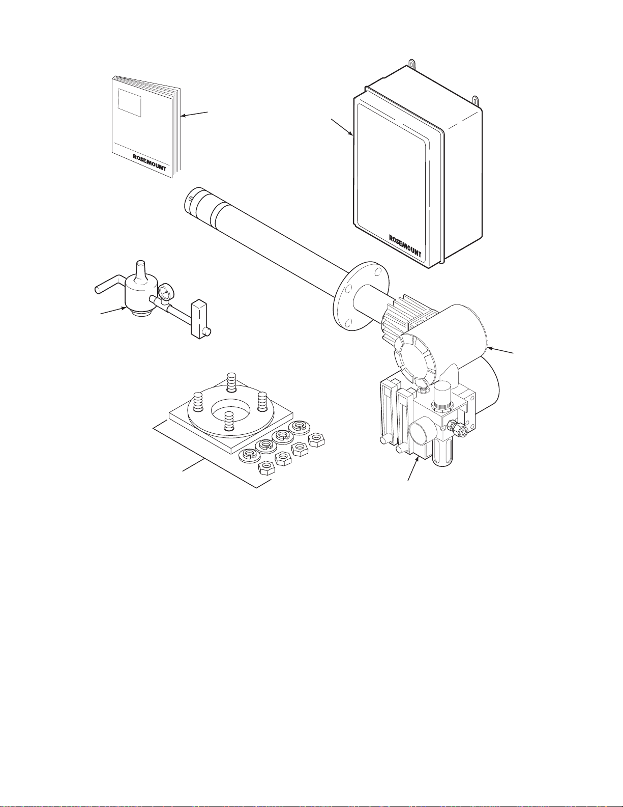
1 1
1
6
2
3
5
4
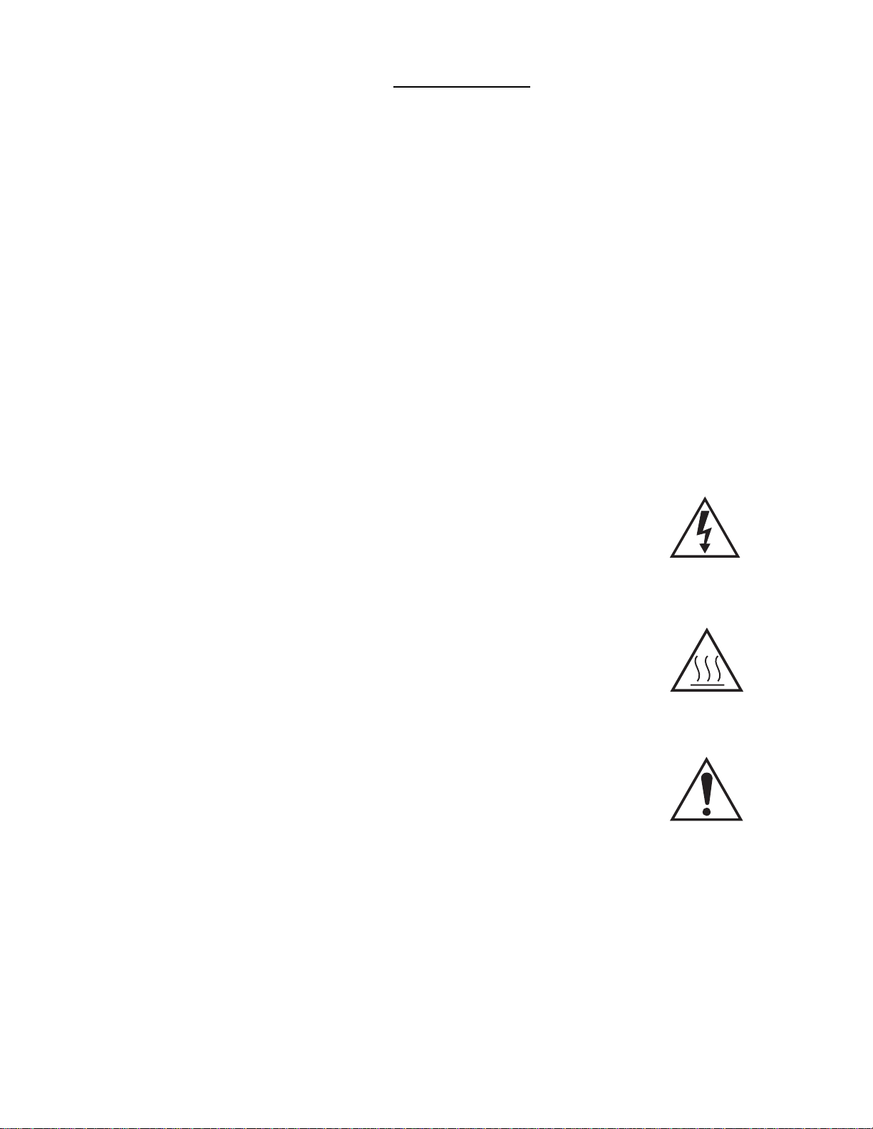
1. Instruction Bulletin
2. IMPS 4000 Intelligent MultiprobeTest Gas Sequencer (Optional)
3. Oxymitter 5000 with Integral Electronics
4. SPS 4000 Single Probe Autocalibration Sequencer (Optional) - (Shown with reference air option)
5. Adaptor Plate with Mounting Hardware and Gasket
6. Reference Air Set (used if SPS 4000 without reference air option or IMPS 4000 not supplied)
Figure 1-1. Typical System Package
IB-106-350
1-0
28550004
Loading...