

Manual: OCX 8800 O2 / Combustibles Transmitter Hazardous Area with Integral Electronics-Rev 1.3 | Rosemount
Rosemount Manual: OCX 8800 O2 / Combustibles Transmitter Hazardous Area with Integral Electronics-Rev 1.3 | Rosemount Manuals & Guides

Rosemount™ OCX 8800 Oxygen and
Combustibles Transmitter
Hazardous Location Probe with Integral Electronics
Reference Manual
00809-0100-4881, Rev AA
July 2018

Signal words and symbols
Pay attention to the following signal words, safety alert symbols, and statements.
WARNING!
Indicates a hazardous situation which, if not avoided, could result in death or serious injury.
CAUTION!
Indicates a hazardous situation which, if not avoided, could result in equipment damage.
NOTICE
Used to address messages or practices not related to personal injury or equipment damage.
Symbols
Earth (ground) terminal
Protective conduit terminal
Risk of electrical shock
Warning: Refer to instruction manual
Essential Instructions
Read this page before proceeding!
Emerson designs, manufactures, and tests its products to meet many national and international standards. Because these
instruments are sophisticated technical products, you must properly install, use, and maintain them to ensure they continue to
operate within their normal specifications. The following instructions must be adhered to and integrated into your safety program
when installing, using, and maintaining Emerson's Rosemount products. Failure to follow the proper instructions may cause any one
of the following situations to occur: loss of life, personal injury, property damage, damage to this instrument, and warranty
invalidation.
• Read all instructions prior to installing, operating, and servicing the product.
• If you do not understand any of the instructions, contact your Emerson representative for clarification.
• Follow all warnings, cautions, and instructions marked on and supplied with the product.
• Inform and educate your personnel in the proper installation, operation, and maintenance of the product.
• Install your equipment as specified in the installation instructions of the appropriate instruction manual and per applicable
local and national codes. Connect all products to the proper electrical and pressure sources.
• To ensure proper performance, use qualified personnel to install, operate, update, program, and maintain the product.
• When replacement parts are required, ensure that qualified people use replacement parts specified by Emerson.
Unauthorized parts and procedures can affect the product's performance, place the safe operation of your process at risk,
and VOID YOUR WARRANTY. Look-alike substitutions may result in fire, electrical hazards, or improper operation.
• Ensure that all equipment doors are closed and protective covers are in place, except when maintenance is being performed
by qualified people, to prevent electrical shock and personal injury.
The information contained in this document is subject to change without notice.
NOTICE
If a Model 375 Field Communicator is used with this unit, the software within the Model 375 may require modification. If a software
modification is required, please contact your local Emerson Service Group or National Response Center at 1-800-654-7768.

Preface
The purpose of this manual is to provide a comprehensive understanding of the OCX8800
components, functions, installation, and maintenance.
Emerson recommends that you thoroughly familiarize yourself with Chapter 1 and Chapter 2 before installing your transmitter.
Before contacting Emerson concerning any questions, first consult this manual. It describes most situations encountered in yoru
equipment's operation and details necessary action.
Chapter 1 presents the basic principles of the transmitter along with its performance characteristics and components. The
remaining sections contain detailed procedures and information necessary to install and service the transmitter.
Product operation personnel
• Read and understand all instructions and operating procedures for this product.
• Install this product as specified in Chapter 2 of this manual per applicable local and national codes.
• Follow all warnings, cautions, and notices marked on and supplied with the product.
• Follow all instructions during the installation, operation,and maintenance of this product.
• To prevent personal injury, ensure that all components are in place prior to and during operation of this product.
• Connect all products to the proper electrical and pressure sources when and where applicable.
• Ensure that all connections to pressure and electrical sources are secure prior to and during equipment operation.
• If you do not understand an instruction or do not feel comfortable following the instructions, contact your Rosemount
representative for clarification or assistance.
• If this instruction manual is not the correct manual for you Rosemount product, call Rosemount at 800 854 8257, and
Rosemount will provide you with the requested manual. You may also download the manual from
www.Emerson.com/RosemountGasAnalysis.
• Save this instruction manual for future reference.
Notice
The contents of this publication are presented for informational purposes only, and while
every effort has been made to ensure their accuracy, they are not to be construed as
warranties or guarantees, expressed or implied, regarding the products or services
described herein or their use or applicability. All sales are governed by Rosemount's terms
and conditions, which are available upon request. We reserve the right to modify or
improve the designs or specifications of such products at any time.
Rosemount does not assume responsibility for the selection, use, or maintenance of any product. Responsibility for proper
selection, use, and mainteance of any Rosemount product remains solely with the purchaser and end-user.
To the best of Rosemount's knowledge, the information herein is complete and accurate. Rosemount makes no warranties,
expressed or implied, including implied warranties of merchantability and fitness for a particular purpose, with respect to this
manual and, in no event, shall Rosemount be liable for any incidental, punitive, special, or consequential damages including, but not
limited to, loss of production, loss of profits, loss of revenue or use, and costs incurred, including without limitation for capital, fuel
and power, and claims of third parties.
Product names used herein are for manufacturer or supplier identification only and may be trademarks/registered trademarks of
these companies.
Rosemount and the Rosemount logo are registered trademarks of Rosemount. The Emerson logo is a trademark and service mark of
Emerson Electric Co.
Warranty
1. LIMITED WARRANTY: Subject to the limitations contained in Section 2 herein, Rosemount warrants that the licensed
firmware embodied in the Goods will execute the programming instructions provided by Rosemount and that the Goods
manufacturerd by Rosemount will be free from defects in materials or workmanship under normal use and care and Services
will be performed by trained personnel using proper equipment and instrumentation for the particular Service provided.
The foregoing warranties will apply until the expiration of the applicable warranty period. Goods are warranted for twelve
(12) months from the date of initial installation or eighteen (18) months from the date of shipment by Rosemount,
whichever period expires first. Consumables and Services are warranted for a period of 90 days from the date of shipment or
completion of the Services. Products purchased by Rosemount from a third party for resale to Buyer ("Resale Products") shall

carry only the warranty extended by the original manufacturer. Buyer agrees that Rosemount has no liability for Resale
Products beyond making a reasonable commercial effort to arrange for procurement and shipping of Resale Products. If
Buyer discovers any warranty defects and notifies Rosemount thereof in writing during the applicable warranty period,
Rosemount shall, at its option, correct any errors that are found by Rosemount in the firmware or Services or repair or
replace F.O.B. point of manufacture that portion of the Goods or firmware found by Rosemount to defective, or refund the
purchase price of the defective portion of the Goods/Services. All replacements or repairs necessitated by inadequate
maintenance, normal wear and usage, unsuitable power sources, or environmental conditions, accident, misuse, improper
installation, modifications, repair, use of unauthorized replacement parts, storage or handling, or any other cause not the
fault of Rosemount are not covered by this limited warranty and shall be at Buyer's expense. Rosemount shall not be
obligated to pay any costs or charges incurred by Buyer or any other party except as may be agreed upon in writing in
advance by Rosemount. All costs of dismantling, reinstallation and freight, and the time and expenses of Rosemount's
personnel and representatives for site travel and diagnosis under this warranty clause shall be borne by Buyer unless
accepted in writing by Rosemount. Goods repaired and parts replaced by Rosemount during the warranty period shall be in
warranty for the remainder of the original warranty period or ninety (90) days, whichever is longer. This limited warranty is
the only warranty made by Rosemount and can be amended only in a writing signed by Rosemount. THE WARRANTIES AND
REMEDIES SET FORTH ABOVE ARE EXCLUSIVE. THERE ARE NO REPRESENTATIONS OR WARRANTIES OF ANY KIND,
EXPRESSED OR IMPLIED, AS TO MERCHANTABILITY, FITNESS FOR PARTICULAR PURPOSE, OR ANY OTHER MATTER WITH
RESPECT TO ANY OF THE GOODS OR SERVICES. Buyer acknowledges and agrees that corrosion or erosion of materials is not
covered by this warranty.
2. LIMITATION OF REMEDY AND LIABILITY: ROSEMOUNT SHALL NOT BE LIABLE FOR DAMAGES CAUSED BY DELAY IN
PERFORMANCE. THE REMEDIES OF BUYER SET FORTH IN THIS AGREEMENT ARE EXCLUSIVE. IN NO EVENT, REGARDLESS OF
THE FORM OF THE CLAIM OR CAUSE OF ACTION (WHETHER BASED IN CONTRACT, INFRINGEMENT, NEGLIGENCE, STRICT
LIABILITY, OTHER TORT OR OTHERWISE), SHALL ROSEMOUNT'S LIABILITY TO BUYER AND/OR ITS CUSTOMERS EXCEED THE
PRICE TO BUYER OF THE SPECIFIED GOODS MANUFACTURED OR SERVICES PROVIDED BY ROSEMOUNT GIVING RISE TO THE
CLAIM OR CAUSE OF ACTION. BUYER AGREES THAT IN NO EVENT SHALL ROSEMOUNT'S LIABILITY TO BUYER AND/OR ITS
CUSTOMERS EXTEND TO INCLUDE INCIDENTAL, CONSEQUENTIAL, OR PUNITIVE DAMAGES. THE TERM "CONSEQUENTIAL
DAMAGES" SHALL INCLUDE, BUT NOT BE LIMITED TO, LOSS OF ANTICIPATED PROFITS, REVENUE, OR USE AND COSTS
INCURRED INCLUDING WITHOUT LIMITATION FOR CAPITAL, FUEL AND POWER, AND CLAIMS OF BUYER'S CUSTOMERS.

Contents
Contents
Chapter 1 Description and specifications ..........................................................................................1
1.1 Component checklist ..................................................................................................................... 1
1.2 System overview ............................................................................................................................ 3
1.2.1 Scope .............................................................................................................................. 3
1.2.2 System description ..........................................................................................................3
1.2.3 System configurations .....................................................................................................4
1.2.4 System features ...............................................................................................................5
1.2.5 System operation ............................................................................................................ 5
1.2.6 Handling the OCX 8800 ...................................................................................................6
1.2.7 System considerations .....................................................................................................6
1.3 Specifications ...............................................................................................................................11
1.3.1 Net O2 range ..................................................................................................................11
1.3.2 Combustibles ................................................................................................................ 11
1.3.3 Accuracy ........................................................................................................................11
1.3.4 System response to test gas .......................................................................................... 11
1.3.5 Temperature limits ........................................................................................................11
1.3.6 Nominal and approximate shipping weights ..................................................................12
1.3.7 Mounting .......................................................................................................................12
1.3.8 Materials ........................................................................................................................12
1.3.9 Calibration .....................................................................................................................13
1.3.10 Calibration gas mixtures recommended (ref. test gas bottles kit #1A9919G04) .............13
1.3.11 Calibration gas flow ....................................................................................................... 13
1.3.12 Reference air ................................................................................................................. 13
1.3.13 Eductor air ..................................................................................................................... 13
1.3.14 Dilution air .....................................................................................................................13
1.3.15 Blowback air (optional) ..................................................................................................13
1.3.16 Certifications ................................................................................................................. 14
1.3.17 Electrical noise ...............................................................................................................14
1.3.18 Line voltage ................................................................................................................... 14
1.3.19 Pollution degree ............................................................................................................ 14
1.3.20 Over voltage category ................................................................................................... 14
1.3.21 Relative humidity ...........................................................................................................15
1.3.22 Isolated output ..............................................................................................................15
1.3.23 Alarm .............................................................................................................................15
1.3.24 Power consumption ...................................................................................................... 15
1.4 Product matrix - OCX 8800 ...........................................................................................................15
Chapter 2 Install .............................................................................................................................19
2.1 Product safety .............................................................................................................................. 19
2.2 Mechanical installation .................................................................................................................20
2.2.1 Selecting a location ....................................................................................................... 20
2.2.2 Installation .....................................................................................................................21
2.3 Electrical installation .................................................................................................................... 26
2.3.1 Electrical connections ....................................................................................................29
2.3.2 Connect line voltage ......................................................................................................29
2.3.3 Connect output signals ..................................................................................................29
2.3.4 O2 4-20 mA signal ..........................................................................................................29
Reference Manual i

Contents
2.3.5 COe 4-20 mA signal ....................................................................................................... 29
2.3.6 Foundation Fieldbus signal ............................................................................................ 29
2.3.7 Alarm output relay .........................................................................................................29
2.3.8 Remote electronics connections to sensor housing ....................................................... 30
2.3.9 Signal connections .........................................................................................................32
2.3.10 Heater power connections .............................................................................................32
2.4 Pneumatic installation ..................................................................................................................32
2.4.1 Reference air set option (only) .......................................................................................32
2.4.2 Reference air set and solenoids option without COe zero function .................................34
2.4.3 Reference air set and solenoids option with COe zero function ......................................36
2.4.4 Reference air set, solenoids, and blowback option with COe zero function .................... 38
2.5 Initial startup ................................................................................................................................42
Chapter 3 Configuration and startup .............................................................................................. 43
3.1 Verify installation ......................................................................................................................... 43
3.1.1 Verify configuration - HART electronics ......................................................................... 43
3.1.2 Verify configuration - Fieldbus electronics ..................................................................... 45
3.2 Initial power up ............................................................................................................................ 46
3.3 Set test gas values ........................................................................................................................ 46
3.3.1 Setting test gas values with the Field Communicator .....................................................46
3.3.2 Setting test gas values with Fieldbus communicator ......................................................46
3.3.3 Setting test gas values with the LOI ................................................................................47
3.4 Calibration solenoids ....................................................................................................................47
3.4.1 Configuring the calibration solenoids with the Field Communicator - HART ...................47
3.4.2 Configuring the calibration solenoids with the Field Communicator - Fieldbus .............. 48
3.4.3 Configuring the calibration solenoids with the LOI .........................................................48
3.5 Blowback feature ......................................................................................................................... 48
3.5.1 Configuring blowback with the Field Communicator - HART ..........................................48
3.5.2 Configuring blowback with the Field Communicator - Fieldbus ......................................49
3.5.3 Configuring blowback with the LOI ................................................................................49
3.6 Calibration verify feature ..............................................................................................................50
3.6.1 Performing a calibration verify with the Field Communicator - HART ............................. 50
3.6.2 Performing a calibration verify with the Field Communicator - Fieldbus .........................51
3.6.3 Performing a calibration verify with the LOI ................................................................... 51
3.7 Calibration tolerance feature ........................................................................................................52
3.7.1 Configuring the calibration tolerance feature with the Field Communicator -HART ....... 52
3.7.2 Configuring the calibration tolerance feature with the Field Communicator -
Fieldbus .........................................................................................................................52
3.7.3 Configuring the calibration tolerance feature with the LOI .............................................53
3.8 COe purge / zero feature .............................................................................................................. 53
3.8.1 Configuring the COe zero feature with the Field Communicator - HART ........................ 54
3.8.2 Configuring the COe zero feature with the Field Communicator - Fieldbus ....................54
3.8.3 Configuring the COe zero feature with the LOI ...............................................................55
3.9 Reset procedure ...........................................................................................................................55
3.9.1 Reset with the LOI ..........................................................................................................56
3.9.2 Reset with Field Communicator .....................................................................................56
Chapter 4 Using the LOI ..................................................................................................................57
4.1 Display orientation .......................................................................................................................57
4.2 LOI controls ..................................................................................................................................58
4.2.1 Overview ....................................................................................................................... 58
4.2.2 LOI key functions ........................................................................................................... 59
ii OCX 8800

Contents
4.2.3 Lockout ......................................................................................................................... 60
4.2.4 LOI status codes .............................................................................................................62
4.3 LOI menu tree .............................................................................................................................. 62
4.3.1 First column submenus ..................................................................................................66
4.3.2 Second column submenus .............................................................................................66
4.3.3 Third and fourth column submenus ...............................................................................67
Chapter 5 Calibration ..................................................................................................................... 69
5.1 Overview ......................................................................................................................................69
5.2 Fully automatic calibration ........................................................................................................... 69
5.2.1 Autocalibration setup using HART ................................................................................. 69
5.3 Operator-initiated autocalibration ............................................................................................... 70
5.3.1 Autocalibration using HART ...........................................................................................70
5.4 Manual calibration ........................................................................................................................70
5.4.1 Manual calibration using the optional LOI ......................................................................71
5.4.2 Manual O2 calibration using the Field Communicator - HART .........................................72
5.4.3 Manual COe calibration using the Field Communicator - HART ...................................... 73
5.4.4 Manual O2 and COe calibration using the Field Communicator - Fieldbus ...................... 75
5.5 D/A trim procedures - LOI .............................................................................................................77
5.5.1 O2 D/A trim procedure using the LOI ............................................................................. 77
5.5.2 COe D/A trim procedure using the LOI ...........................................................................78
5.6 D/A trim procedures - HART ......................................................................................................... 79
5.6.1 O2 D/A trim procedure using HART ................................................................................79
5.6.2 COe D/A trim procedure using HART ............................................................................. 81
Chapter 6 Field Communicator .......................................................................................................83
6.1 Overview ......................................................................................................................................83
6.2 Field Communicator connections .................................................................................................83
6.2.1 Connecting to a HART loop ............................................................................................83
6.2.2 Connecting to a Fieldbus segment .................................................................................84
6.3 HART menu tree ...........................................................................................................................86
6.4 Fieldbus menu tree .......................................................................................................................90
Chapter 7 Foundation Fieldbus .......................................................................................................95
7.1 Foundation Fieldbus technology .................................................................................................. 95
7.1.1 Overview ....................................................................................................................... 95
7.1.2 Introduction .................................................................................................................. 95
7.1.3 Function blocks ............................................................................................................. 96
7.1.4 Device descriptions ....................................................................................................... 97
7.1.5 Instrument-specific function blocks ...............................................................................97
7.2 Network communication ............................................................................................................. 98
7.2.1 Link active scheduler (LAS) .............................................................................................99
7.2.2 Device addressing ..........................................................................................................99
7.3 OCX function blocks ...................................................................................................................100
7.3.1 Implemented function blocks ......................................................................................100
7.4 Resource block ...........................................................................................................................100
7.4.1 PlantWeb Alerts ...........................................................................................................100
7.4.2 Mapping of PWA ..........................................................................................................101
7.4.3 PWA SIMULATE ............................................................................................................110
7.4.4 Fieldbus/PWA simulate ................................................................................................111
7.4.5 Configure simulation from AMS ...................................................................................111
7.5 Configure simulation with the Model 375 Field Communicator ..................................................112
7.5.1 Support resource block errors ......................................................................................113
Reference Manual iii

Contents
7.6 Transducer block ........................................................................................................................113
7.6.1 Transducer block parameters ...................................................................................... 114
7.7 Transducer block enumerations ................................................................................................. 122
7.7.1 Calibration states .........................................................................................................122
7.7.2 Calibration step command .......................................................................................... 123
7.7.3 Transducer block channel assignments for AI blocks ....................................................128
7.7.4 Transducer block channel status ..................................................................................128
7.7.5 Transducer block simulate ...........................................................................................129
7.7.6 Support transducer block errors .................................................................................. 129
7.8 Analog input (AI) function block .................................................................................................130
7.8.1 Introduction ................................................................................................................ 130
7.8.2 Simulation ...................................................................................................................135
7.8.3 Filtering .......................................................................................................................138
7.8.4 Signal conversion .........................................................................................................138
7.8.5 Direct signal conversion ...............................................................................................138
7.8.6 Indirect signal conversion ............................................................................................ 139
7.8.7 Indirect square root ..................................................................................................... 139
7.8.8 Block errors ................................................................................................................. 139
7.8.9 Modes ......................................................................................................................... 140
7.8.10 Alarm detection ...........................................................................................................140
7.8.11 Status handling ............................................................................................................141
7.8.12 Advanced features .......................................................................................................142
7.8.13 Application information ...............................................................................................142
7.8.14 Application examples .................................................................................................. 143
7.8.15 Pressure transmitter used to measure level in an open tank .........................................143
7.8.16 Differential pressure transmitter to measure flow ........................................................147
7.8.17 Troubleshooting ..........................................................................................................147
7.9 Proportional/integral/derivative (PID) function block ................................................................. 149
7.9.1 Setpoint selection and limiting .................................................................................... 158
7.9.2 PID equation structures ............................................................................................... 160
7.9.3 Reverse and direct action .............................................................................................161
7.9.4 Reset limiting .............................................................................................................. 161
7.9.5 Block errors ................................................................................................................. 161
7.9.6 Modes ......................................................................................................................... 162
7.9.7 Alarm detection ...........................................................................................................162
7.9.8 Status handling ............................................................................................................163
7.9.9 Application information ...............................................................................................164
7.9.10 Application examples .................................................................................................. 165
7.9.11 Cascade control with master and slave loops ............................................................... 167
7.9.12 Cascade control with override ..................................................................................... 169
7.9.13 Troubleshooting ..........................................................................................................170
7.10 Airthmetic (ARTHM) function block ............................................................................................172
7.10.1 Block errors ................................................................................................................. 175
7.10.2 Modes ......................................................................................................................... 176
7.10.3 Alarm detection ...........................................................................................................176
7.10.4 Block execution ........................................................................................................... 177
7.10.5 Compensation input calculations ................................................................................ 177
7.10.6 Application information ...............................................................................................178
7.11 Advanced topics .........................................................................................................................179
7.11.1 Arithmetic types ..........................................................................................................179
7.11.2 Troubleshooting ..........................................................................................................180
iv OCX 8800

Contents
7.12 Input selector (ISEL) function block ............................................................................................ 181
7.12.1 Block errors ................................................................................................................. 185
7.12.2 Modes ......................................................................................................................... 185
7.12.3 Alarm detection ...........................................................................................................186
7.12.4 Block execution ........................................................................................................... 186
7.12.5 Status handling ............................................................................................................187
7.12.6 Application information ...............................................................................................187
7.12.7 Troubleshooting ..........................................................................................................189
7.13 Operation with Emerson DeltaV ................................................................................................. 189
7.13.1 About AMS and DeltaV software ..................................................................................189
Chapter 8 Troubleshooting .......................................................................................................... 193
8.1 Overview ....................................................................................................................................193
8.1.1 Grounding ................................................................................................................... 193
8.1.2 Electrical noise .............................................................................................................193
8.1.3 Electrostatic discharge ................................................................................................ 193
8.1.4 Total power loss ...........................................................................................................194
8.2 Diagnostic alarms .......................................................................................................................196
8.3 Fault isolation .............................................................................................................................196
8.4 Alarm relay events ......................................................................................................................205
Chapter 9 Maintenance and service .............................................................................................. 209
9.1 Overview ....................................................................................................................................209
9.2 Removal and installation ............................................................................................................ 209
9.2.1 OCX with integral electronics ...................................................................................... 209
9.2.2 OCX with remote electronics ....................................................................................... 213
9.2.3 Repair sensor housing ..................................................................................................216
9.2.4 Sensor housing assembly .............................................................................................233
9.3 Repair electronics housing ......................................................................................................... 248
9.3.1 Electronics housing disassembly .................................................................................. 248
9.3.2 Electronics housing assembly ...................................................................................... 252
Chapter 10 Replacement parts ....................................................................................................... 255
10.1 Sensor housing ...........................................................................................................................255
10.2 Electronics housing .................................................................................................................... 259
10.3 O2 cell and heater strut assembly ............................................................................................... 262
Appendices and reference
Appendix A Safety data ................................................................................................................... 265
A.1 Safety Instructions ..................................................................................................................... 265
A.2 Safety data sheet for ceramic fiber products .............................................................................. 266
A.2.1 Identification ............................................................................................................... 266
A.2.2 Physical data ................................................................................................................266
A.2.3 Hazardous ingredients .................................................................................................267
A.2.4 Fire and explosion data ................................................................................................ 267
A.2.5 Health hazard data ...................................................................................................... 267
A.2.6 Reactivity data .............................................................................................................269
A.2.7 Spill or leak procedures ................................................................................................269
A.2.8 Special precautions ......................................................................................................269
Reference Manual v

Contents
A.3 High pressure gas cylinders ........................................................................................................ 271
A.3.1 General precautions for handling and storing high pressure gas cylinders ....................271
A.4 ATEX clarification ....................................................................................................................... 272
A.4.1 ATEX compliant gas analysis performed within a flameproof enclosure ....................... 272
Appendix B SPA with HART Alarm ................................................................................................... 275
B.1 Overview ....................................................................................................................................275
B.2 Description ................................................................................................................................ 275
B.3 Installation ................................................................................................................................. 277
B.4 Setup ......................................................................................................................................... 277
B.4.1 Jumper and switch settings ..........................................................................................278
B.4.2 Configuration/calibration ............................................................................................ 279
Appendix C Returning material ....................................................................................................... 285
Appendix D ......................................................................................................................................287
vi OCX 8800

Description and specifications
1 Description and specifications
1.1 Component checklist
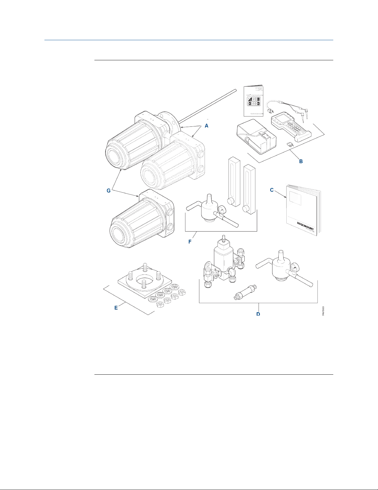
A typical OCX 8800 Oxygen/Combustibles Transmitter package contains the items shown
in Figure 1-1.
Reference Manual 1
Description and specifications
Typical system packageFigure 1-1:
A. Hazardous Area OCX 8800 with integral electronics
B. Field communicator package (optional)
C. Quick Start Guide
D. Blowback hardware (optional)
E. Adapter plate with mounting hardware and gasket
F. Reference air and calibration set (optional)
G. Hazardous Area OCX 8800 with remote electronics
Use the product matrix in Table 1-1 at the end of this section to verify your order number.
The first part of the matrix defines the model. The last part defines the various options and
features of the OCX 8800. Check the model number against the transmitter features and
options, making sure options specified by this number are on or included with the unit.
Use this complete model number for any correspondence with Emerson. A list of
accessories for use with the OCX 8800 is provided in Table 1-2.
2 OCX 8800

1.2 System overview
1.2.1 Scope
This Instruction Manual supplies details needed to install, start up, operate, and maintain
the OCX 8800. Signal conditioning electronics output a digital signal representing oxygen
(O2) and combustibles (COe) values. This information, plus additional details, can be
accessed with the 375 Field communicator or Emerson AMS software..
1.2.2 System description
The OCX 8800 is designed to measure oxygen and combustible concentrations in flue gas
temperatures up to 1427 °C (2600 °F). Electrical connections, power, and communications
are made through two 3/4 NPT ports in the flameproof electronics enclosure using fittings
and cables provided by you. Cable installation must meet NEC, IEC, and/or other applicable
national or local codes for Class I, Zone 1, Group IIB +H2 T3/T6 permanently mounted
equipment. The transmitter is close coupled to the process and requires minimum sample
conditioning requirements.
Description and specifications
The equipment measures oxygen percentage by reading the voltage developed across a
heated electrochemical cell, which consists of a small yttria-stabilized, zirconia disc. Both
sides of the disc are coated with porous metal electrodes. When operating at the proper
temperature, the following Nernst equation gives the millivolt output of the cell.
EMF = KT log10 (P1/P2) + C
where:
1. P2 is the partial pressure of the oxygen in the measured gas on one side of the cell.
2. P1 is the partial pressure of the oxygen in the reference air on the opposite side of
the cell.
3. T is the absolute temperature.
4. C is the cell constant.
5. K is an arithmetic constant.
Note
For best results, use clean, dry instrument air (20.95% oxygen) as the reference air.
When the cell is at operating temperature and there are unequal oxygen concentrations
across the cell, oxygen ions travel from the high oxygen partial pressure side to the low
oxygen partial pressure side of the cell. The resulting logarithmic output voltage is
approximately 50 mV per decade. The output is proportional to the inverse lograrithm of
the oxygen concentration. Therefore, the output signal increases as the oxygen
concentration of the sample decreases. This characteristic enables the transmitter to
provide exceptional sensitivity at low oxygen concentrations.
Reference Manual 3

Description and specifications
The transmitter measures net oxygen concentration in the presence of all the products of
combustion, including water vapor. Therefore, it may be considered an analysis on a wet
basis. In comparison with older methods, such as the portable apparatus, which provides
an analysis on a dry gas basis, the wet analysis will, in general, indicate a lower percentage
of oxygen.
The combustibles sensor is a catalytic sensor consisting of two resistance devices (RTD).
One RTD is the reference element covered with an inert coating. The other RTD element is
active, coated with a catalyst. As the sample gases flow by the sensor, the combustible
gases oxidize on the surface of the active element. The temperature difference produces a
resistance relationship between the two elements that is directly proportional to the
concentration of combustibles in the sample gases.
The catalyst is specifically designed to detect carbon monoxide (CO), but the sensor
responds to other combustible gases. The sensor is calibrated using CO; thus the output
should be expressed in terms of CO. However, as the sensor detects other combustible
gases, the output cannot just be labeled CO. The response of the sensor to other
combustible gases gives an output that is equivalent to the sensor detecting CO.
The term COe is used in this manual to describe the sensor output. This term indicates that
the sensor is calibrated in terms of CO and that the sensor output is equivalent to CO but
not specific to CO.
1.2.3
Dilution air is provided by the COe sensors to ensure that there is adequate oxygen to fully
oxidize any combustible gases regardless of the concentration of oxygen in the process.
System configurations
Transmitters are available in four lengths, giving you flexibility to use a penetration
appropriate to the size of the stack or duct. The length options are 18 in. (457 mm), 3 ft
(0.91 m), 6 ft (1.83 m), or 9 ft (2.7 m). Probes are available in three material options: 316L
stainless steel, Inconel 600, and ceramic to accommodate higher temperatures.
The electronics are contained in a separate housing from the sensors. When the
transmitter is configured with the integral electronics option, the electronics and sensor
housings are mounted as a unit at the stack mounting flange. When the transmitter is
configured with the remote electronics option, the electronics are contained in a separate
housing from the sensors. The electronics housing may be mounted up to 150 feet from
the sensor housing.
The electronics control both sensor temperatures and provide output signals in one of two
ways:
1. Individual 4-20 mA isolated outputs that are proporational to the measured oxygen
and combustibles concentrations. The oxygen output also contains HART
communication.
2. Single Foundation Feldbus output.
The power supply can accept voltages of 100 to 240 Vac and 50 to 60 Hz. The electronics
accepts millivolt signals generated by the snesors and produces the outputs to be used by
remotely connected devices. Refer to Chapter 3 for specific instructions upon intial power
up.
4 OCX 8800

1.2.4 System features
1. The O2 cell output voltage and sensitivity increase as the oxygen concentration
decreases.
2. HART or Foundation Fieldbus communication is standard. To use this capability, you
must have either:
a. Model 375 Field Communicator
b. Asset Management Solutions (AMS) software for the PC
3. Oxygen cell and heater/thermocouple assembly are field replaceable.
4. Electronics are automatically configured for line voltages from 100 to 240 Vac.
5. You can calibrate and diagnostically troubleshoot the transmitter in one of two
ways:
a. LOI: The LOI is mounted to the end of the electronics module and allows local
communications with the electronics. Refer to Chapter 4 for more information.
b. HART or Foundation Fieldbus interface: The transmitter's output line transmits a
digital signal with the detected oxygen or combustible levels encoded in a digital
format. This information can be accessed through the following:
• Model 375 Field Communicator - The handheld field communicator requires
Device Description (DD) software specific to the OCX 8800. The DD software
is supplied with many Model 375 units, but can also be programmed into
existing units at most Emerson service offices. Refer to Chapter 6Section for
additional information.
• Personal computer (PC) - The use of a personal computer requires AMS
software available from Emerson.
• Selected distributed control systems - The use of distributed control systems
requires input/output (I/O) hardware and AMS software which permit HART
communications.
6. When the transmitter is configured without the LOI, you must calibrate and
diagnostically troubleshoot the transmitter using the HART of Foundation Fieldbus
interface.
7. Optional blowback system: The blowback system periodically blows instrument air
back through the sample line filter and out the sample tube. This clears out
particulate and keeps the sample line filter from clogging.
Description and specifications
1.2.5
Reference Manual 5
System operation
Figure 1-2 shows the relationship between the components of the OCX 8800. The sensors
and the electronics are contained in separate housings. The sensor housing and probe
mount to a duct or process wall so that the probe protrudes into the flue gas stream. An air
powered eductor continuously pulls samples of the process flue gas through the probe to a
chamber in front of the sensor housing where the sample passes the O2 sensor and
continues on the COe sensor. Dilution air is provided to the COe sensor and reference air to
the O2 sensor. After the gas sample flows past the O2 sensor and through the COe sensor,
it is drawn through the eductor where it mixes with the eductor air and exits through
exhaust back into the system. The electronics housing contains the CPU and
communication boards which convert the sensor inputs into digital output signals. The

Description and specifications
CPU can also initiate and perform calibrations. Three test gases and instrument air can be
turned on and off by solenoids. Test gas flow to the sensors is regulated by a flow meter
between the electronics and sensor housings. Instrument air is separated into eductor air,
reference air, and dilution air. The instrument air solenoid does not allow air flow until the
heaters are up to temperature. This minimizes the amount of sampled process flue gas
being pulled into the cold sensors causing condensation.
System operation diagramFigure 1-2:
1.2.6 Handling the OCX 8800
CAUTION!
EQUIPMENT DAMAGE
Only handle printed circuit boards and integrated circuits when adequate anti-static
precautions have been taken to prevent possible equipment damage.
The OCX 8800 is designed for industrial application. Treat each component of the system with
care to avoid physical damage. The probe may contain components made from ceramics,
which are susceptible to shock when mishandled.
1.2.7
System considerations
Prior to installing your OCX 8800, make sure you have all the components necessary to
make the system installation. Ensure that all components are properly integrated to make
the system functional.
After verifying that you have all the components, select mounting locations and determine
how each component will be placed in terms of available line voltage, ambient
temperatures, environmental considerations, convenience and serviceability. Figure 1-4
shows a typical system wiring for a system with integral electronics. Figure 1-5 shows
6 OCX 8800

Description and specifications
simplified installations for the OCX 8800.Figure 1-5 shows the dimensions for the optional
sample tube support. Figure 1-6 shows the dimensions for the optional in-situ filters.
Figure 1-7 shows the optional panel mounted blowback.
A source of instrument air is required at the OCX 8800 for reference air, dilution air, and
eductor air. As the OCX 8800 is equipped with an in-place calibration feature, make
provisions for connecting test gas tanks to the OCX 8800 when it is to be calibrated.
Note
The electronics module is designed to meet Type 4X and IP66, and the electronic components are
rated to temperatures up to 85 °C (185 °F ).
Retain packaging in which the unit arrived from the factory in case any components are to be
shipped to another site. This packaging has been designed to protect the product.
Figure 1-3:
Communications Connections and AMS application - Hazardous Area OCX
8800 with Integral Electronics
Reference Manual 7

Description and specifications
Typical System Installation - Integral ElectronicsFigure 1-4:
A. Adapter plate
B. Signal outputs (twisted pairs)
C. Line voltage
D. Instrument air supply (reference gas)
E. High O2 test gas
F. Low O2 test gas
G. CO test gas
8 OCX 8800

Description and specifications
Optional Sample Tube SupportFigure 1-5:
C. 0.75 (19) dia. on 7.5 (190) dia. B.C. 8 places
D. 0.75 (19) dia. on 4.75 (121) dia. B.C. 4 places
Reference Manual 9

Description and specifications
Probe length L
18 in. 24.5 (621)
3 ft 42.5 (1078)
6 ft 78.5 (1993)
9 ft 114.5 (2907)
Optional In-Situ FiltersFigure 1-6:
Figure 1-7:
Optional Panel Mounted Blowback and Calibration/Reference Air Set (19
in. Rack or Wall Mount)
10 OCX 8800

1.3 Specifications
1. Requires XPS transmitter, P/N 6A00358G03
Note
All static performance characteristics are with operating variables constant. Specifications subject to
change without notice.
1.3.1 Net O2 range
0-1% to 0-40% O2, fully field selectable
1.3.2 Combustibles
0-1,000 ppm to 0-5%, fully field selectable
1.3.3 Accuracy
Description and specifications
1.3.4
1.3.5
Oxygen
±0.75% of reading or 0.5% O2 (whichever is greater)
Combustibles
±2% range
System response to test gas
Oxygen
10 sec T90
Combustibles
25 sec T90
Temperature limits
Process
0 to 1427 °C (32 to 2600 °F)
Reference Manual 11

Description and specifications
Sensors housing
-40 to 100 °C (-40 to 212 °F)
Electronics housing
-40 to 65 °C (-40 to 149 °F), ambient
-40 to 85 °C (-40 to 185 °F), internal operating temperature of electronics inside housing,
as read by HART® or FOUNDATION Fieldbus™.
1.3.6 Nominal and approximate shipping weights
18 in. (457 mm) probe package
54 lb (20 kg)
3 ft (0.91 m) probe package
1.3.7
1.3.8
55 lb (20.5 kg)
6 ft (1.83 m) probe package
57 lb (21 kg)
9 ft (2.74 m) probe package
59 lb (22 kg)
Mounting
Flange
Materials
Probes
316 stainless steel: 705 °C (1300 °F)
Inconel 600: 1000 °C (1832 °F)
Ceramic: 1427 °C (2600 °F)
Enclosures
Low copper aluminum
12 OCX 8800

Description and specifications
1.3.9 Calibration
Semi-automatic or automatic
1.3.10 Calibration gas mixtures recommended (ref. test gas
bottles kit #1A9919G04)
0.4% O2, balance N
8% O2, balance N
1000 ppm CO, balance air
2
2
1.3.11 Calibration gas flow
7 scfh (3.3 L/m), regulated to 20 to 30 psi (138 to 207 kPa)
1.3.12 Reference air
2 scfh (1 L/m), clean, dry, instrument-quality air (20.95% O2), regulated to 45 psi (310 kPa)
1.3.13 Eductor air
5 scfh (2.5 L/m), clean, dry, instrument-quality air (20.95% O2), regulated to 45 psi (310
kPa)
1.3.14
Dilution air
0.1 scfh (0.05 L/m), clean, dry, instrument-quality air (20.95% O2), regulated to 45 psi (310
kPa)
1.3.15
Reference Manual 13
Blowback air (optional)
Clean, dry, instrument-quality air (20.95% O2), regulated to ≥ 60 psi (413 kPa) or greater
and ambient temperature of ≥ -18 °C (0 °F)

Description and specifications
1.3.16 Certifications
Complies with the following standards:
• 22.2 No. 94-M91; 22.2 No. 60529:05; ANSI/ISA S82.02.01; ANSI/ISA 12.00.01:2002;
ANSI/ISA 12.22.01:2002;UL No. 50 (Ed 10); CAN/CSA C22.2 No. 61010-1-12;
CAN/CSA C22.2 No. 60079-0:15; CAN/CSA C22.2 No. 60079-1:16; ISA 60079-0
(12.00.01) – 2013; ISA 60079-0 (12.00.01) – 2013; ISA 60079-1 (12.22.01) – 2009
(R2013) ISA 61010-1-12
• ATEX: En 60079-0 : 2011 + A11 : 2013, EN 60079-1 : 2014, IEC 60079-0 : 2017
1.3.17
1.3.18
1.3.19
Special conditions of use:
- Flame proof joints are not intended to be repaired.
- Avoid installations that could cause electrostatic build-up on the painted
surfaces, and only clean the painted surfaces with a damp cloth.
• IECEx: IEC 60079-0: 2004, Edition 4; IEC 60079-1: 2014, Edition 7.0
• FM: Class 3600:1998; Class 3810:2005; ANSI/ISA 12.00.01:2005; ANSI/ISA
12.22.01:2002; ANSI/ NEMA 250:1991; ANSI/ISA 60529:2004
Electrical noise
Meets EN 61326, Class A
Line voltage
Universal 100 to 240 Vac ± 10%, 50 to 60 Hz, no switches or jumpers required, 3/4-14 NPT
conduit port
Pollution degree
2
1.3.20
14 OCX 8800
Over voltage category
II

1.3.21 Relative humidity
5 to 95% (non-condensing)
1.3.22 Isolated output
Oxygen
4-10 mAdc, 950 ohm maximum with HART or FOUNDATION Fieldbus capability only
Combustibles
4-20 mAdc, 950 ohm maximum (not present with FOUNDATION Fieldbus)
1.3.23 Alarm
Alarm output relay - dry contact, form C, 30 mA, 30 Vdc capability
Description and specifications
1.3.24 Power consumption
750 W maximum
1.4
Product matrix - OCX 8800
Product matrix - OCX 8800Table 1-1:
OCX88C O2 Combustibles Transmitter - Flameproof
Code Probe length and material
00 No probe or exhaust tube
11 18 in. (457 mm) 316 stainless steel tube up to 704 °C
12 3 ft (0.91 m) 316 stainless steel tube up to 704 °C (1300 °F)
13 6 ft (1.83 m) 316 stainless steel tube up to 704 °C (1300 °F)
14 9 ft (2.7 m) 316 stainless steel tube up to 704 °C (1300 °F)
21 18 in. (457 mm) Inconel 600 up to 1000 °C (1832 ° F)
22 3 ft (0.91 m) Inconel 600 up to 1000 °C (1832 ° F)
23 6 ft (1.83 m) Inconel 600 up to 1000 °C (1832 ° F)
24 9 ft (2.7 m) Inconel 600 up to 1000 °C (1832 ° F)
31 18 in. (457 mm) ceramic up to 1427 °C (2600 °F )
32 3 ft (0.91 m) ceramic up to 1427 °C (2600 °F )
(1300 °F )
Reference Manual 15

Description and specifications
Code Probe mounting assembly
10 (ANSI 2 in. 150 lb) 6 in. diameter flange. 4.75 in. BC with 4 x
20 (DIN) 185 mm diameter flange, 145 mm BC with 4 x 18 mm
21 (DIN) 185 mm diameter flange, 145 mm BC with 4 x 18 mm
Code Mounting hardware - stack side
0 No adapter plate (0 must be chosen under Mounting adapter -
1 New installation - square weld plate with studs
2 Model 218/240 mounting plate (with model 218/240 shield
3 Existing model 218/240 support shield
4 Competitor's mount
5 Model 132 adapter plate
Product matrix - OCX 8800 (continued)Table 1-1:
0.75 in. diameter holes - standard O2 cell
diameter holes - standard O2 cell
diameter holes -high sulfur O2 cell
probe side below)
removed)
Code Mounting hardware - probe side
0 No adapter plate
1 Probe only (ANSI)
4 Probe only (DIN)
Electronics housing - NEMA 4X, IP66 HART communica-
Code
H1 HART communications - basic unit
H2 HART communications - local operator interface
H3 HART communications - calibration solenoids
H4 HART communications - local operator interface and calibra-
F1 Fieldbus communications - basic unit
F2 Fieldbus communications - local operator interface
F3 Fieldbus communications - calibration solenoids
F4 Fieldbus communications - local operator interface and cali-
Code Electronics mounting
01 Integral to sensor housing electronics
02 Split architecture with no cable
tions
tion solenoids
bration solenoids
Code In-situ filter
0 None
2 High surface area stainless steel
16 OCX 8800

Description and specifications
Product matrix - OCX 8800 (continued)Table 1-1:
3 Hastelloy
Code Accessories
0 None
2 Cal. gas/flow rotometers & ref. gas set
3 Cal. gas/flow rotometers & ref. gas set w/blowback
4 Cal. gas/flow rotometers & ref. gas set w/blowback - panel
mounted
02 In-situ filter (stainless steel only)
3
Example OCX88C111011H30600
1. Provide details of the existing mounting plate as follows:
Plate with studs Bolt circle diameter, number, and arrangement of
studs, stud thread, stud height above mounting plate.
Plate without studs Bold circle diameter, number, and arrangement of
holes, thread, depth of stud mounting plate with accessories.
AccessoriesTable 1-2:
Part number Description
1A99119H01 Oxygen test gas bottle; 0.4% O2, balance N
1A99119H02 Oxygen test gas bottle; 8.0% O2, balance N
1A99119H07 CO test gas bottle; 1,000 ppm CO, balance air
1A99120H02 Regulator for oxygen (may need 2)
1A99120H03 Regulator for CO test gas
1A99119G06 Wall mount bracket for test gas bottles
1A99119G05 Test gas regulators kit
1A99119G04 Test gas bottles kit
1A9929H01 Moore industries SPA for low O2 alarm, high COe alarm, calibration status, and
unit fail
4851B40G01 Wall or pipe mounting kit
1A9978H02 375 field communicator with 12 megabyte buffer, model no. 375HR1EKLU
6A00171G01 Power line filter kit
6A00288G01 Sample tube support, 18 in. (457 mm)
6A00288G02 Sample tube support, 3 ft (0.91 mm)
6A00288G03 Sample tube support, 6 ft (1.83 m)
6A00288G04 Sample tube support, 9 ft (2.7 m)
2
2
Reference Manual 17

Description and specifications
Part number Description
6P00162H01 Flange insulator
Accessories (continued)Table 1-2:
18 OCX 8800

2 Install
WARNING!
Before installing this equipment, read Section A.1. Failure to follow safety instructions could
result in serious injury or death.
WARNING!
ELECTRICAL HAZARD
Install all protective equipment covers and safety ground leads after installation. Failure to
install covers and ground leads could result in serious injury or death.
WARNING!
HAZARDOUS AREAS
The Xi Advanced Electronics can be installed in general purpose areas only. Do not install the Xi
in hazardous areas or in the vicinity of flammable liquids.
Install
2.1
WARNING!
ELECTRICAL HAZARD
If external loop power is used, the power supply must be a safety extra low voltage (SELV)
type.
NOTICE
All unused ports on the probe housing and Xi enclosure should be plugged with a suitable
filling.
Product safety
WARNING!
Before installing this equipment, read Appendix A. Failure to follow the safety instructions
could result in serious injury or death.
CAUTION!
HAZARDOUS AREAS
The OCX88A can be installed in general purpose areas only. Do not install the OCX88A in
hazardous areas.
Reference Manual 19

Install
CAUTION!
FLAMEPROOF DEVICES
To maintain explosion-proof protection of the OCX88C in hazardous areas, all cable entry
devices and blanking elements for unused apertures must be certified flameproof, suitable for
the conditions of use, and properly installed.
CAUTION!
HIGH TEMPERATURE SURFACES
To maintain explosion-proof protection of the OCX88C in hazardous areas, the sensor housing
must not be mounted to any surface or flange that exceeds 195 °C (383 °F).
CAUTION!
HIGH TEMPERATURE SAMPLE
To maintain explosion-proof protection of the OCX88C in hazardous areas, the sample entering
the sensor housing must not exceed 195 °C (383 °F).
2.2 Mechanical installation
2.2.1 Selecting a location
The location of the OCX 8800 in the stack or flue is most important for maximum accuracy
in the oxygen analyzing process. The probe must be positioned so the gas it measures is
representative of the process. Best results are normally obtained if the transmitter is
positioned near the center of the duct (40 - 60% insertion). Longer ducts may require
several transmitters, as the oxygen and combustibles can vary due to stratification. A point
too near the wall of the duct or the inside radius of a bend may not provide a
representative sample because of the very low flow conditions. Select the sensing point so
that the process gas temperature falls within the range of the probe material used.
Figure 2-1 through #unique_73/fig_ght_spm_gz provide mechanical installation references.
The ambient temperature inside the electronics housing must not exceed 85 °C (185 °F) .
Procedure
1. Check the flue or stack for holes and air leakage. The presence of this condition
substantially affects the accuracy of the oxygen and combustibles readings.
Therefore, either make the necessary repairs or install the transmitter upstream of
any leakage.
2. Ensure the area is clear of internal and external obstructions that will interfere with
installation and maintenance access to the unit. Allow adequate clearance for the
removal of the OCX 8800.
20 OCX 8800
 Loading...