

Manual: OCX 8800 O2 / Combustibles Transmitter General Purpose with Remote Electronics-Rev 1.3 | Rosemount
Rosemount Manual: OCX 8800 O2 / Combustibles Transmitter General Purpose with Remote Electronics-Rev 1.3 | Rosemount Manuals & Guides

Reference Manual
00809-0300-4880, Rev AA
July 2018
Rosemount
OCX 8800 Oxygen and
Combustibles Transmitter
General Purpose Probe with Remote Electronics
TM

Reference Manual
4880, Rev AA
July 2018
OCX 8800
TOC-2
00809-0300-
SECTION 1
Description and
Specifications
SECTION 2
Installation
SECTION 3
Configuration and
Startup
Table of Contents
Essential Instructions ........................................................................................ i
Preface ............................................................................................................... ii
Definitions .......................................................................................................... ii
Symbols .............................................................................................................. ii
Component Checklist ................................................................................... 1-1
System Overview .......................................................................................... 1-1
Specifications ..............................................................................................1-12
Mechanical
Installation ...................................................................................................... 2-2
Electrical Installation ..................................................................................... 2-8
Pneumatic Installation ................................................................................2-14
Initial Startup ................................................................................................2-20
Verify Installation ........................................................................................... 3-1
Initial Power Up ............................................................................................. 3-3
Set Test Gas Values .................................................................................... 3-4
OCX 8800 Reset Procedure ....................................................................... 3-4
SECTION 4
Using HART
Communications
SECTION 5
Calibration
SECTION 6
Maintenance and Service
Overview ........................................................................................................ 4-1
Field Communicator Sig na l Conn ec tio ns .................................................. 4-1
Field Communicator PC Connections ........................................................ 4-4
HART Menu Tree .......................................................................................... 4-5
D/A Trim Procedures .................................................................................... 4-9
Overview ........................................................................................................ 5-1
Fully Automatic Calibration .......................................................................... 5-1
Operator - Initiated Autocalibration ............................................................ 5-3
Manual Calibration ........................................................................................ 5-3
Overview ........................................................................................................ 6-1
OCX 8800 Removal
and Installation .............................................................................................. 6-1
OCX with
Remote Electronics ................................................................................. 6-2
Repair Sensor Housing ................................................................................ 6-8
Sensor Housing Disassembly ............................................................... 6-8
Sensor Housing Assembly .................................................................. 6-18
Repair Electronics Housing ...................................................................... 6-28
Electronics Housing Disassembly ..................................................... 6-28

Reference Manual
July 2018
OCX 8800
00809-0300-4880, Rev AA
Electronics Housing Assembly ........................................................... 6-30
Replace Tube Fittings ................................................................................6-34
Remove Tube Fittings ..........................................................................6-34
Install Tube Fittings ...............................................................................6-35
SECTION 7
Troubleshooting
SECTION 8
Replacement Parts
APPENDIX A
Safety Data
APPENDIX B
SPA with HART Alarm
APPENDIX C
Return of Materials
Overview ........................................................................................................ 7-1
Grounding ................................................................................................. 7-1
Electrical Noise ........................................................................................ 7-1
Electrostatic Discharge........................................................................... 7-1
Total Power Loss .................................................................................... 7-2
Diagnostic Alarms ......................................................................................... 7-2
Fault Isolation ................................................................................................ 7-3
Alarm Relay Events ....................................................................................7-11
Sensor Housing ............................................................................................. 8-2
Electronics Housing ...................................................................................... 8-6
O2 Cell and Heater Strut Assembly ........................................................... 8-9
Safety Instructions . . . . . . . . . . . . . . . . . . . . . . . . . . . . . . . . . . . . . . . . A-2
Safety Data Sheet for Ceramic Fiber Products . . . . . . . . . . . . . . . . . A-24
High Pressure Gas Cylinders . . . . . . . . . . . . . . . . . . . . . . . . . . . . . . A-30
Overview . . . . . . . . . . . . . . . . . . . . . . . . . . . . . . . . . . . . . . . . . . . . . . . B-1
Description. . . . . . . . . . . . . . . . . . . . . . . . . . . . . . . . . . . . . . . . . . . . . . B-1
Installation . . . . . . . . . . . . . . . . . . . . . . . . . . . . . . . . . . . . . . . . . . . . . . B-2
Setup . . . . . . . . . . . . . . . . . . . . . . . . . . . . . . . . . . . . . . . . . . . . . . . . . . B-2
Returning Material . . . . . . . . . . . . . . . . . . . . . . . . . . . . . . . . . . . . . . . .C-1

Reference Manual
4880, Rev AA
July 2018
OCX 8800
TOC-2
00809-0300-
ESSENTIAL
INSTRUCTIONS
Rosemount OCX 8800
Oxygen and Combustibles
Transmitter
Emerson designs, manufactures and tests its products to meet many national
and international standards. Because these instruments are sophisticated
technical products, you MUST properly install, use, and maintain them to
ensure they continue to operate within their normal specifications. The
following instructions MUST be adhered to and integrated into your safety
program when installing, using, and maintaining Emerson’s Rosemount
products. Failure to follow the proper instructions may cause any one of the
following situations to occur: Loss of life; personal injury; property damage;
damage to this instrument; and warranty invalidation.
•
Read all instructions prior to installing, operating, and servicing the
product.
•
If you do not understand any of the instructions, contact your
Emerson representative for clarification.
•
Follow all warnings, cautions, and instructions marked on and
supplied with the product.
•
Inform and educate your personnel in the proper installation,
operation, and maintenance of the product.
•
Install your equipment as specified in the Installation Instructions
of the appropriate Instruction Manual and per applicable local and
national codes. Connect all products to the proper electrical and
pressure sources.
•
To ensure proper performance, use qualified personnel to install,
operate, update, program, and maintain the product.
•
When replacement parts are required, ensure that qualified people use
replacement parts specified by Emerson. Unauthorized parts and
procedures can affect the product's performance, place the safe
operation of your process at risk, and VOID YOUR WARRANTY.
Look-alike substitutions may result in fire, electrical hazards, or
improper operation.
•
Ensure that all equipment doors are closed and protective covers
are in place, except when maintenance is being performed by
qualified persons, to prevent electrical shock and personal injury.
READ THIS PAGE BEFORE PROCEEDING!
The information contained in this document is subject to change without
notice.
If a Model 275/375 Universal HART® Communicator is used with this unit, the software
within the Model 275/375 may require modification. If a software modification is required,
please contact your local Emerson Service Group or National Response Center at 1-800654-7768.
Reference Manual
July 2018
OCX 8800
00809-0300-4880, Rev AA
PREFACE The purpose of this manual is to provide a comprehensive understanding of
the OCX 8800 components, functions, installation, and maintenance.
We recommend that you thoroughly familiarize yourself with the Introduction
and Installation sections before installing your transmitter.
The introduction presents the basic principles of the transmitter along with its
performance characteristics and components. The remaining sections contain
detailed procedures and information necessary to install and service the
transmitter.
Before contacting Emerson concerning any questions, first consult this
manual. It describes most situations encountered in your equipment's
operation and details necessary action.
DEFINITIONS The following definitions apply to WARNINGS, CAUTIONS, and NOTES
found throughout this publication.
Highlights an operation or maintenance procedure, practice, condition, statement, etc. If not
strictly observed, could result in injury, death, or long-term health hazards of personnel.
SYMBOLS
Highlights an operation or maintenance procedure, practice, condition, statement, etc. If not
strictly observed, could result in damage to or destruction of equipment, or loss of
effectiveness.
NOTE
Highlights an essential operating procedure, condition, or statement.
: EARTH (GROUND) TERMINAL
: PROTECTIVE CONDUCTOR TERMINAL
: RISK OF ELECTRICAL SHOCK
: WARNING: REFER TO INSTRUCTION BULLETIN
NOTE TO USERS
The number in the lower right corner of each illustration in this publication is a
manual illustration number. It is not a part number, and is not related to the
illustration in any technical manner.

Reference Manual
4880, Rev AA
July 2018
OCX 8800
ii
00809-0300-
Section 1 Description and Specifications
Component Checklist . . . . . . . . . . . . . . . . . . . . . . . . . . . . . page 1-1
System Overview . . . . . . . . . . . . . . . . . . . . . . . . . . . . . . . . page 1-1
Specifications . . . . . . . . . . . . . . . . . . . . . . . . . . . . . . . . . . . page 1-12
COMPONENT
CHECKLIST
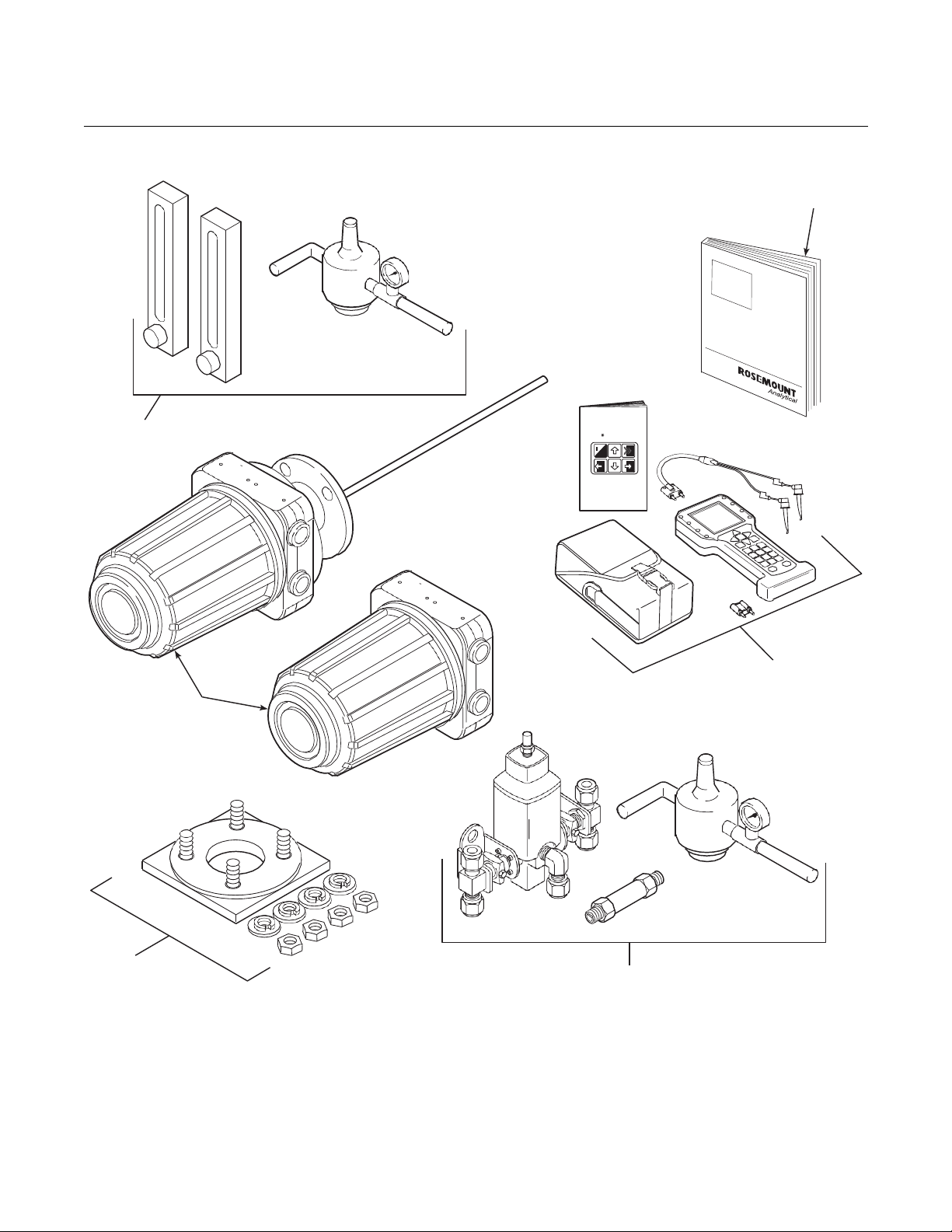
SYSTEM OVERVIEW Scope
A typical OCX 8800 Oxygen/Combustibles Transmitter package should
contain the items shown in Figure 1-1.
Use the product matrix in Table 1-1 at the end of this section to verify your
order number. The first part of the matrix defines the model. The last part
defines the various options and features of the OCX 8800. Check the model
number against the transmitter features and options, making sure options
specified by this number are on or included with the unit. Use this complete
model number for any correspondence with Emerson. A list of accessories
for use with the OCX 8800 is provided in Table 1-2.
This Instruction Manual supplies details needed to install, startup, operate,
and maintain the OCX 8800. Signal conditioning electronics outputs separate
4-20 mA signals representing oxygen (O
This information, plus additional details, can be accessed with the HART
Model 275/375 handheld communicator or Rosemount AMS software.
) and combustibles (COe) values.
2
System Description
The OCX 8800 is designed to measure oxygen and combustible
concentrations in flue gas temperatures up to 2600°F (1427°C). Electrical
connections, power and communications are made through two 3/4 NPT ports
in the flameproof electronics enclosure using fittings and cables provided by
the customer. Cable installation must meet NEC, IEC and/or other applicable
national or local codes for Class I, Zone 1, Group IIB +H2 T3/T6 permanently
mounted equipment. The transmitter is close coupled to the process and
requires minimal sample conditioning requirements.
Reference Manual
4880, Rev AA
July 2018
OCX 8800
1-2
1
4
6
MAN 4275A00
o
FISHER
-ROSEMOUNT
TM
2 3
37390076
Figure 1-1. Typical System Package
English
October 1994
HART Communicator
00809-0300-
5
1.
Instruction Manual
2.
Field Communicator Package (optional)
3.
Adapter Plate with Mounting Hardware and Gasket
4.
Reference Air and Calibration Set
5.
Blowback Hardware (optional)
6.
OCX 8800 with Remote Electronics

Reference Manual
July 2018
OCX 8800
1-3
00809-0300-4880, Rev AA
The equipment measures oxygen percentage by reading the voltage
developed across a heated electrochemical cell, which consists of a small
yttria-stabilized, zirconia disc. Both sides of the disc are coated with porous
metal electrodes. When operated at the proper temperature, the millivolt
output of the cell is given by the following Nernst equation:
EMF = KT log10 (P
Where:
1.
P2 is the partial pressure of the oxygen in the measured gas on one side
of the cell.
2.
P1 is the partial pressure of the oxygen in the reference air on the
opposite side of the cell.
3.
T is the absolute temperature.
4.
C is the cell constant.
5.
K is an arithmetic constant.
NOTE
For best results, use clean, dry instrument air (20.95% oxygen) as the
reference air.
When the cell is at operating temperature and there are unequal oxygen
concentrations across the cell, oxygen ions will travel from the high oxygen
partial pressure side to the low oxygen partial pressure side of the cell. The
resulting logarithmic output vo ltag e is approximately 50 mV per decade. The
output is proportional to the inverse logarithm of the oxygen concentration.
Therefore, the output signal increases as the oxygen concentration of the
sample gas decreases. This characteristic enables the OCX 8800 to provide
exceptional sensitivity at low oxygen concentrations.
1/P2
) + C
The OCX 8800 measures net oxygen concentration in the presence of all the
products of combustion, including water vapor. Therefore, it may be
considered an analysis on a "wet" basis. In comparison with older methods,
such as the portable apparatus, which provides an analysis on a "dry" gas
basis, the "wet" analysis will, in general, indicate a lower percentage of
oxygen. The difference will be proportional to the water content of the
sampled gas stream.
The OCX 8800 combustibles sensor is a catalytic sensor consisting of two
Resistance Devices (RTD). One RTD is the reference element covered with
an inert coating. The other RTD element is active, coated with a catalyst. As
the sample gases flow by the sensor, the combustible gases oxidize on the
surface of the active element. The oxidation that occurs produces heat and a
temperature rise in the active element. The temperature difference produces
a resistance relationship between the two elements that is directly
proportional to the concentration of combustibles in the sample gases.

1-4
Reference Manual
July 2018
OCX 8800
00809-0300-4880, Rev AA
The catalyst is specifically designed to detect carbon monoxide (CO), but the
sensor responds to other combustible gases. The sensor is calibrated using
CO, thus the output should be expressed in terms of CO. However, since the
sensor detects other combustible gases, the output cannot just be labeled
CO. The response of the sensor to other combustible gases gives an output
that is equivalent to the sensor detecting CO. The term COe is used in this
manual to describe the sensor output. This term indicates that the sensor is
calibrated in terms of CO, and that the sensor output is equivalent to CO but
not specific to CO.
Dilution air is provided to the COe sensor to ensure there is adequate oxygen
to fully oxidize any combustible gases regardless of the concentration of
oxygen in the process.
System Configuration
Transmitters are available in four lengths, giving the user the flexibility to use
a penetration appropriate to the size of the stack or duct. The length options
are 18 in. (457 mm), 3 ft (0.91 m), 6 ft (1.83 m), or 9 ft (2.7 m). Probes are
available in three material options, 316L stainless steel, inconel 600, and
ceramic to accommodate higher temperatures.
The electronics are contained in a separate housing from the sensors. The
electronics housing may be mounted up to 150 feet away from the sensor
housing.
The electronics control both sensor temperatures and provide individual 4-20
mA isolated outputs that are proportional to the measured oxygen and
combustibles concentrations. The power supply can accept voltages of 100 to
240 VAC and 50 to 60 Hz. The electronics accepts millivolt signals generated
by the sensors and produces the outputs to be used by remotely connected
devices. The outputs are isolated 4-20 mA linearized currents. Refer to
Section 3, Configuration and Startup for specific instructions upon initial
power up.
System Features
1.
The O2 cell output voltage and sensitivity increase as the oxygen
concentration decreases.
2.
HART communication is standard. To use the HART capability, you
must have either:
a.
Model 275/375 Field Communicator.
b.
AMS software for the PC.
3.
Oxygen cell and heater /t he rmocouple assembly are field replaceable.
4.
Electronics are automatically configured for line voltages from 100 to
240 VAC.

Reference Manual
July 2018
OCX 8800
1-5
00809-0300-4880, Rev AA
5.
An operator can calibrate and diagnostically troubleshoot the OCX 8800
using the HART Interface. Each of the OCX 8800's 4-20 mA output lines
transmit an analog signal proportional to oxygen or combustible levels
detected. The HART output is superimposed on the oxygen 4-20 mA
output line only. This information can be accessed through the following:
•
Model 275/375 Handheld Communicator - The handheld
communicator requires Device Description (DD) software specific
to the OCX 8800. The DD software will be supplied with many
Model 275/375 units, but can also be programmed into existing
units at most Emerson service offices. Refer to Section 4, Using
HART Communications, for additional information.
•
Personal Computer (PC) - The use of a personal computer
requires AMS software available from Emerson.
•
Selected Distributed Control Systems - The use of distributed
control systems requires input/output (I/O) hardware and AMS
software which permit HART communications.
6.
Optional Blowback System. The blowback system periodically blows
instrument air back throug h the sample line filter a nd o ut the s ample
tube. This clears out particulate and keeps the sample line filter from
clogging.
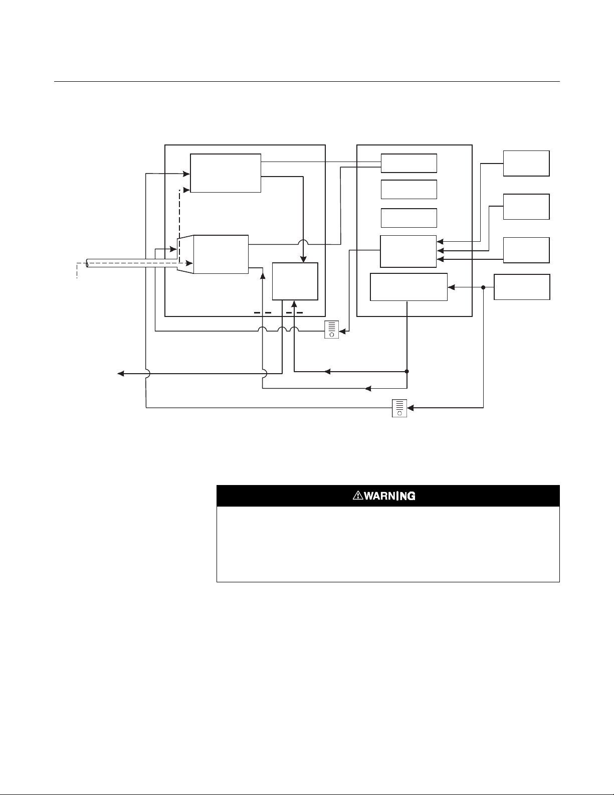
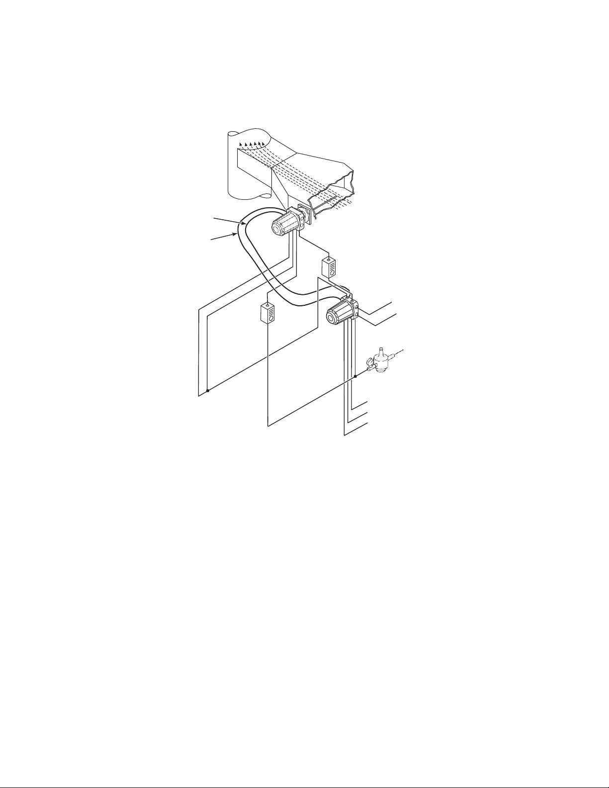
System Operation
Figure 1-2 shows the relationship between the components of the OCX 8800.
The sensors and the electronics are contained in separate housings. The
sensor housing and probe mounts to a duct or process wall so that the probe
protrudes into the flue gas stream. An air powered eductor continuously pulls
samples of the process flue gas through the probe to a chamber in front of the
sensor housing where the sample passes the O
the COe sensor. Dilution air is provided to the COe sensor and reference air
to the O
the COe sensor, it is drawn through the eductor where it mixes with the
eductor air and exits through exhaust back into the system. The electronics
housing contains the CPU and HART boards which convert the sensor inputs
into 4-20 mA analog output signals. The CPU can also initiate and perform
calibrations. Three test gasses and instrument air can be turned on and off by
solenoids. Test gas flow to the sensors is regulated by a flow meter between
the electronics and sensor housings. Instrument air is separated into eductor
air, reference air, and dilution air. The instrument air solenoid does not allow
air flow until the heaters are up to temperature. This minimizes the amount of
sampled process flue gas being pulled into cold sensors causing
condensation.
sensor. After the gas sample flows past the O2 sensor and through
2
sensor and continues on to
2
1-6
Reference Manual
July 2018
OCX 8800
Test Gas
37390001
Figure 1-2. System Operation Diagram
Probe
Combustibles
Sensor
Sample
Gas
Exhaust
SENSOR
HOUSING
COe
Sensor
O
2
Eductor
Reference Air
Flow Meter
7 scfh
ELECTRONICS
Instrument Air
Eductor Air
HOUSING
CPU
HART
Board
Power
Supply
Optional
Test Gas
Solenoids
Solenoid
00809-0300-4880, Rev AA
Low O
2
High O
2
Test Gas
CO
Test Gas
Instrument
Air
Dilution Air
Flow Meter
50 cc/min.
(0.1 scfh)
Handling the OCX 8800
It is important that printed circuit boards and integrated circuits are handled only when
adequate antistatic precautions have been taken to prevent possible equipment damage.
The OCX 8800 is designed for industrial application. Treat each component of the system
with care to avoid physical damage. The probe may contain components made from
ceramics, which are susceptible to shock when mishandled.
System Considerations
Prior to installing your OCX 8800, make sure you have all the components
necessary to mak e the system installation. Ens ure al l t he c omponents are
properly integrated to make the system functional.
Reference Manual
July 2018
OCX 8800
1-7
00809-0300-4880, Rev AA
After verifying that you have all the components, select mounting locations
and determine how each component will be placed in terms of available line
voltage, ambient temperatures, environmental considerations, convenience,
and serviceability. Figure 1-3 shows a typical system wiring. Simplified
installations for the OCX 8800 are shown in Figure 1-4. Figure 1-6 shows the
dimensions for the optional sample tube support.
A source of instrument air is required at the OCX 8800 for reference air,
dilution air, and eductor air. Since the OCX 8800 is equipped with an in-place
calibration feature, provision should be made for connecting test gas tanks to
the OCX 8800 when it is to be calibrated.
NOTE
The electronics module is designed to meet NEMA 4 (IP66) and the electronic
components are rated to temperatures up to 185°F (8 5°C).
Retain packaging in which the unit arrived from the factory in case any
components are to be shipped to another site. This packaging has been
designed to protect the product.
Figure 1-3. OCX 8800 HART
Connections and AMS Application

1-8
Reference Manual
July 2018
OCX 8800
37390064
Figure 1-4. Typical System
Installation
Power Ca ble
[up to 150 ft (46 m)]
Signal Cable
[up to 150 ft (46 m)]
Figure 1-5. OCX 8800 HART
Heater
Gases
Stack
Dilution
Air
Flow
Meter
00809-0300-4880, Rev AA
Duct
Flow Meter
OCX 8800 with
REMOTE
ELECTRONICS
Test Gas
Pressure
Regulator
High O2 Test Gas
Low O
CO Test Gas
4-20 mA Outputs
(2 Twisted Pairs)
Line Voltage
Instrument Air
Supply
(Reference Gas)
Test Gas
2

Reference Manual
July 2018
OCX 8800
1-9
00809-0300-4880, Rev AA
Connections and AMS Application
Reference Manual
July 2018
OCX 8800
1-10
Figure 1-6. Sample Tube Support
00809-0300-4880, Rev AA
Reference Manual
July 2018
OCX 8800
1-11
37390064
00809-0300-4880, Rev AA
Figure 1-7. Typical System
Installation
Power Ca ble
[up to 150 ft (46 m)]
[up to 150 ft (46 m)]
Heater
Signal Cable
Gases
Stack
Dilution
Air
Flow
Meter
Duct
Flow Meter
OCX 8800 with
REMOTE
ELECTRONICS
Test Gas
Pressure
Regulator
High O2 Test Gas
Low O
CO Test Gas
4-20 mA Outputs
(2 Twisted Pairs)
Line Voltage
Instrument Air
Supply
(Reference Gas)
Test Gas
2

Reference Manual
July 2018
OCX 8800
1-12
Blowback Air (optional) Clean, dry, instrument-quality air (20.95% O2), regulated to ≥ 60 psi
SPECIFICATIONS General Purpose OCX
Specifications
Net O2 Range 0-1% to 0-40% O2, fully field selectable
Combustibles 0-1000 ppm to 0-5%, fully field selectable
Accuracy
Oxygen ± 0.75% of reading or 0.05% O
Combustibles ± 2% range
System Response to
Test G as
Oxygen 10 sec T90
Combustibles 25 sec T90
Temperature Limits
Process 32°to 2600°F (0° to 1427°C)
Sensors Housing -40°to 212°F (-40°to 100°C), ambient
Electronics Housing -40°to 149°F (-40°to 65°C), ambient
Nominal and Approximate
Shipping Weights
18 in. (457 mm)
probe package
3 ft (0.91 m) probe
package
6 ft (1.83 m) probe
package
9 ft (2.74 m) probe
package
Mounting and Mounting
Positions
Sensors Housing Flange
Electronics Housing Wall/Pipe
Materials
Probes 316L stainless steel - 1300°F (704°C)
Enclosures Low-copper aluminum
Calibration Semi-aut omatic or automatic
Calibration Gas Mixtures
Recommended
(Ref. test gas bottles
kit #1A99119G04)
Calibration Gas Flow 7 scfh (3.3 l/m)
Reference Air 2 scfh (1 l/m), clean, dry instrument-quality air (20.95% O
Eductor Air 5 scfh (2.5 l/m), clean, dry, instrument-qualit y air 20.95% O
Dilution Air 0.1 scfh (0. 5 l/m), clean, dry, instrument-quality air (20.95% O
00809-0300-4880, Rev AA
(whichever is greater)
-40°to 185°F (-40°to 85°C), internal - operating temperature of
electronics inside instrument housing, as measured by a HART
communicator or AMS software
2
54 lbs (20 kg)
55 lbs (20.5 kg)
57 lbs (21 kg)
59 lbs (22 kg)
Inconel 600 - 1832°F (1000°C)
Ceramic - 2600°F (1427°C)
0.4
% O2, Balance N2
8% O
, Balance N2
2
1000 ppm CO, Balance Air
regulated to 35 psi (241 kPa)
regulated to 35 psi (241 kPa)
regulated to 35 psi (241 kPa)
(413 kPa) or greater and ambient temperature of ≥ 0 °F (-18 °C)
Table continued on next page
),
2
),
2
)
2
Reference Manual
July 2018
OCX 8800
1-13
C
U
00809-0300-4880, Rev AA
Specifications
Sensors Housing NEMA 4, IP66 with fitting and pipe on reference exhaust port to clean, dry
atmosphere, two 3/4-14 NPT conduit ports (when reference vents are
routed to a dry area).
Electronics Housing NEMA 4, IP66 with fitting and pipe on reference exhaust port to clean, dry
atmosphere, two 3/4-14 NPT conduit ports (when reference vents are
routed to a dry area).
Electrical Noise EN 61326-1, Class A
Line Voltage Universal 100 to 240 VAC ±
jumpers required, 3/4-14 NPT conduit port
Pollution Degree 2
Over Voltage Category II
Relative Humidity 5 to 95% (non-condensing)
Isolated Output
Oxygen 4-20 mAdc, 950 ohm maximum, with HART capability
Combustibles 4-20 mAdc, 950 ohm maximum
Alarm Alarm output relay - dry contact, form C, 30mA, 30VDC capacity
Power Consumption 750 W maximum
Mounting and Mounting
Positions
Sensor Housing Flange
Electronics Housing
NOTE
All static performance characteristics are with operating variables constant. Specifications subject to change
without notice.
Wall/Pipe
Certifications
S
10%, 50 to 60 Hz, no switches or
Reference Manual
July 2018
OCX 8800
1-14
OCX88A
O2/Combustibles Transmitter
Code
Probe Length and Material
00
No Probe or Exhaust Tube
11
18 in. (457 mm) 316 SST
up to 1300°F (704°C)
(3)
21
18 in. (457 mm) Inconel 600
up to 1832°F (1000°C)
31
18 in. (457 mm) Ceramic
up to 2600°F (1427°C)
12
3 ft (0.91 m ) 316 SST
up to 1300°F (704°C)
22
3 ft (0.91 m) Inconel 600
up to 1832°F (1000°C)
(3)
32
3 ft (0.91 m) Ceramic
up to 2600°F (1427°C)
13
6 ft (1.83 m ) 316 SST
up to 1300°F (704°C)
23
6 ft (1.83 m) Inconel 600
up to 1832°F (1000°C)
(3)
14
9 ft (2.7 m) 316 SST
up to 1300°F (704°C)
24
9 ft (2.7 m) Inconel 600
up to 1832°F (1000°C)
(3)
Code
Probe Mounting Assembly
10
(ANSI 2 in. 150 lb) 6" dia. flange, 4.75" BC with 4 x 0.75" dia. holes
20
(DIN) 185 mm dia. flange, 145 mm BC with 4 x 18 mm dia. holes
Code
Mounting Hardware - Stac k Side
0 No Adapter Plate (“0” must be chosen under “Mounting Adapter - Probe Side” below)
1 New Installation - Square weld plate with studs
2 Model 218/240 Mounting Plate (with Model 218/240 Shiel d Removed)
3 Existing Model 218/240 Support Shield
4 Special Mounting
(1)
5 Model 132 Adapter Plate
Code
Mounting Hardware - Probe Side
0 No Adapter Plate
1 Probe Only (ANSI)
2 Probe Only (DIN)
Code
Electronics Housing - Communications
H1
HART Communications
H2
HART Communicatio ns with Local Operator Interface
H3
HART Communications with Calibration Solenoids
H4
HART Communications with Local Operator Interface and C alibrati on Solenoids
Code
Electronics Mounting
01
Integr al to Sensor H ousing
02
Remote Electronic s and no cable
03
Remote Electronics and 20 ft (6 m) cable
04
Remote Electronics and 40 ft (12 m) cable
05
Remote Electronics and 60 ft (18 m) cable
06
Remote Electronics and 80 ft (24 m) cable
07
Remote Electronics and 100 ft (30 m) cable
08
Remote Electronics and 150 ft (46 m) cable
Code
Accessories
00
None
01
Flow meters & Ref. Air Set
02
In-Situ Filte r (Stainless Steel only)
(2) 03
In-Situ Filter (SST), Flow meters & Ref. Air Set
(2)
11
Flow meters, and Ref. Air Set with Blowback
12
In-Situ Filter (SST) with Blowback
(2) 13
In-Situ Filter (SST), Flow meters & Ref. Air Set with Blowback
(2)
OCX88A
11
10 1 1
H3
06
02
Example
Plate with studs
Bolt circle diameter, number, and arrangement of studs, stud thread, stud height above mounting plate.
Plate without studs
Bolt circle diameter, number, and arrangement of holes, thread, depth of stud mounting plate with accessories.
00809-0300-4880, Rev AA
Table 1-1. Product Matrix - General Purpose OCX 8800
NOTES:
(1)
Provide details of the existi ng mo unti ng pl at e as foll o ws:
(2)
For use with stainless steel sample tube only.
(3)
For high temperature applications that require a filter, please order 1A99762H03 separately.

Reference Manual
July 2018
OCX 8800
1-15
PART NUMBER DESCRIPTION
00809-0300-4880, Rev AA
Table 1-2. Accessories
1A99119H01 Oxygen test gas bottle; 0.4% O2, balance N
1A99119H02 Oxygen test gas bottle; 8.0% O2, balance N
1A 99119H07 CO test gas bottle; 1000 ppm CO, balance air
1A99120H02 Regulator for Oxygen (may need 2)
1A99120H03 Regulator for CO test gas
1A99119G06 Wall mount bracket for test gas bottles
1A99119G05 Test gas regulators kit
1A99119G04 Test gas bottles kit
1A99292H01
1A99339H03 Blowback valve, air operated
1A99762H03 Hasteloy In Situ Filter, High Temperature
1A99784H02
6A00171G01 Power line filter kit
6A00288G01 Sample Tube Support, 18 in. (457 mm)
6A00288G02 Sample Tube Support, 3 Ft. (0.91 m)
6A00288G02 Sample Tube Support, 6 Ft. (1.83 m)
6A00288G04 Sample Tube Support, 9 Ft. (2.7 m)
6P00162H02 Flange Insulator
Moore Industries SPA for Low O
Calibration Status, and Unit Fail
375 Field Communicator with 12 Megabyte buffer,
model no. 375HR1EKLU
Alarm, High COe Alarm,
2
2
2
Reference Manual
July 2018
OCX 8800
00809-0300-4880, Rev AA
Section 2 Installation
Mechanical Installation . . . . . . . . . . . . . . . . . . . . . . . . . . . page 2-2
Electrical Installation . . . . . . . . . . . . . . . . . . . . . . . . . . . . . page 2-8
Pneumatic Installation . . . . . . . . . . . . . . . . . . . . . . . . . . . . page 2-14
Initial Startup . . . . . . . . . . . . . . . . . . . . . . . . . . . . . . . . . . . . page 2-20
Before installing this equipment, read the "Safety instructions for the wiring and installati on
of this apparatus" in Appendix A: Safety Data. Failure to follow the safety instructions could
result in serious injury or death.
The OCX88A can be installed in general purpose areas only. Do not install the OCX88A in
hazardous areas.
Reference Manual
July 2018
OCX 8800
2-2
00809-0300-4880, Rev AA
MECHANICAL
INSTALLATION
Selecting Location
1.
The location of the OCX 8800 in the stack or flue is most important for
maximum accuracy in the oxygen analyzing process. The probe must
be positioned so the gas it measures is representative of the process.
Best results are normally obtained if the transmitter is positioned near
the center of the duct (40-60% insertion). Longer ducts may require
several transmitters since the oxygen and combustibles can vary due to
stratification. A point too near the wall of the duct or the inside radius of
a bend, may not provide a representative sample because of the very
low flow conditions. The sensing point should be selected so the
process gas temperature falls within the range of probe material used.
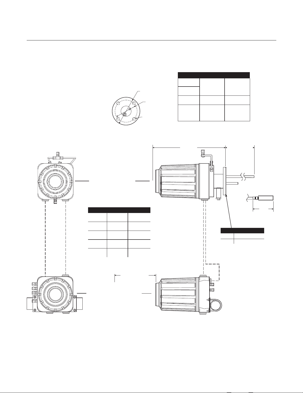
Figure 2-1 through Figure 2-4 provide mechanical installation
references. The ambient temperature inside the electronics housing
must not exceed 185°F (85°C).
2.
Check the flue or stack for holes and air leakage. The presence of this
condition will substantially affect the accuracy of the oxygen and
combustibles readings. Therefore, either make the necessary repairs or
install the transmitter up stream of any leakage.
3.
Ensure the area is clear of internal and external obstructions that will
interfere with installation and maintenance access to the unit. Allow
adequate clearance for the removal of the OCX 8800.
Do not allow the temperature of the electronics housing to exceed 185°F (85°C) or damage
to the electronics may result.
Whenever a positive stack pressure exists at the installation site, be sure to connect all
pneumatic lines prior to installing the OCX 8800 in the stack or ductwork. Failure to connect
the pneumatic lines can allow the flow of contaminants into the OCX 8800 ports.
Installation
1.
Ensure all components are available to install the OCX 8800.
2.
The OCX 8800 may be installed intact as it is received.
3.
Weld or bolt adapter plate (Figure 2-2) onto the duct.
4.
Use the pipe or wall mounting hardware as shown in Figure 2-3 to
mount the electronics housing. Choose a location not to exceed the
length of the electronics cable ordered.
5.
Ensure the conduits drop vertically from the OCX 8800 and the conduit
is routed below the level of the conduit ports on the housing to form a
drip loop. Drip loops minimize the possibility that moisture will damage
the electronics (Figure 2-4).
6.
Where a positive stack pressure exists at the installation site, connect all
pneumatic lines prior to installing the OCX 8800 in the stack or
ductwork.
Reference Manual
00809
July 2018
OCX 8800
2-3
-0300-4880, Rev AA
NOTE
If process temperatures will exceed 392°F (200°C), use anti-seize compound
on stud threads to ease future removal of the OCX 8800.
7.
Insert sample and exhaust tubes through the opening in the mounting
flange and bolt the unit to the flange.
Uninsulated stacks or ducts may cause ambient temperatures in the electronics housing to
exceed 185°F (85°C) and damage the electronics.
8.
If insulation is removed to access the duct for OCX 8800 mounting,
make sure to replace insulation afterward.
Enclosures
The OCX 8800 enclosures are designed to meet ingress conditions of IP66.
Each enclosure cover is threaded to its base and sealed with an o-ring that
isolates the threads from external contaminants.
Each cover is secured by a clip attached to the base that engages the cover
between the ribs of the cover sidewall. The clip is held in place by an Allen
head cap screw and lockwasher mounted in a recess. Cover removal and
installation requires an Allen wrench to loosen and tighten the screw.
Reference Manual
July 2018
OCX 8800
4-2
Table 2. Installation/Removal
18
(457)
34
(864)
36
(914)
52
(1321)
72
(1829)
88
(2235)
108
(2743)
124
(3150)
0.06 In. Thick Gasket
ANSI
3535B18H02
DIN
3535B45H01
Heater
Po
wer Cab
le
Signal Cable
Signal Cable
Heater
Po
wer Cab
le
37390009
Table
1. Mounting
Flange
ANSI
DIN
5R10244H01
5R10244H02
Flange
Dia.
6.00
7.28
(152)
(185)
Hole
0.75
0.71
Dia.
(19)
(18)
(4) Holes
spaced on
(121)
(145)
B.C. dia
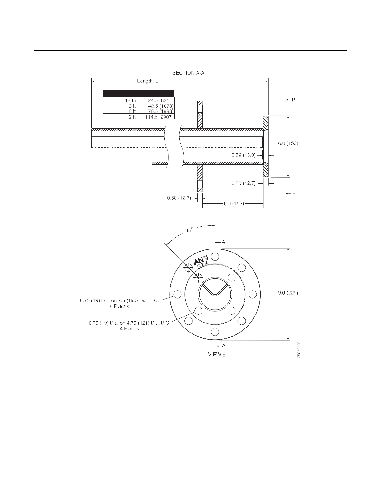
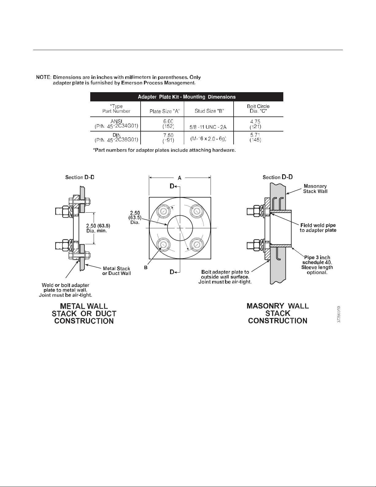
Figure 2-1. Installation, OCX 8800
NOTE
All dimensions are in inches with millimeters in parentheses.
Insulate if exposed to adverse weather or extreme temperature
changes, install a protective housing and/or insulation
around the unit.
See Table 1
See Table 2
SENSOR HOUSING
Probe Dim "A” Dim "B”
18 in.
Flange Dia.
B.C. Dia.
Hole Dia.
equally
Removal Envelope
Dim “B”
00809-0300-4880, Rev AA
4.75
5.71
Insertion Depth
Dim “A”
Optional
In Situ FIilter
8.3
(211)
3 ft
6 ft
9 ft
Allow 9 in.
(229 mm) for
Cover Removal
ELECTRONICS HOUSING
Reference Manual
00809
July 2018
OCX 8800
2-5
-0300-4880, Rev AA
Figure 2-2. Adapter Plate Installat ion
Reference Manual
July 2018
OCX 8800
6-2
37020021
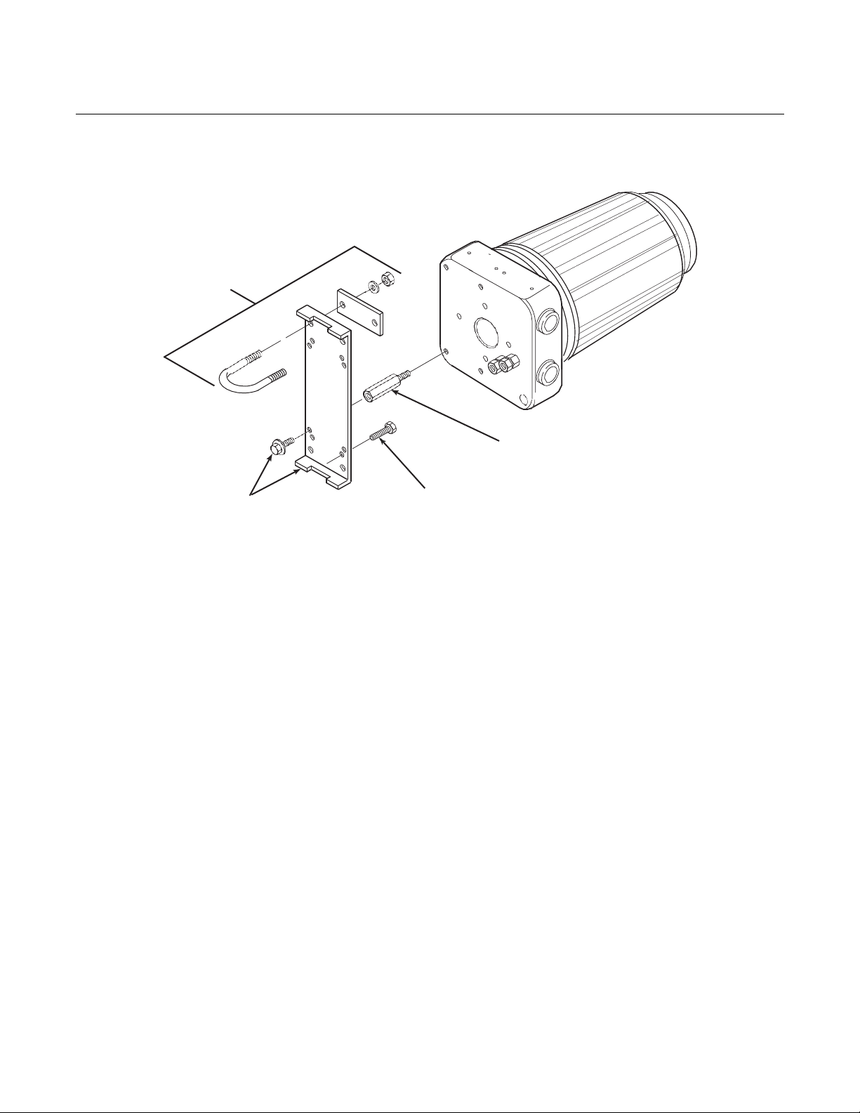
Figure 2-3. Wall or Pipe Mounting
of Electronics Housing
Note: * Indicates items are included
in mounting kit P/N 4851B40G01.
*Pipe
Mounting
Clamp
*Wall or Pipe
Mounting Bracket
and Screws
00809-0300-4880, Rev AA
Electronics
Housing
Wall Mounting Bolts
or Lag Screws
(4 each by customer)
1/4-20 UNC x 2 in. M-F Standoffs.
Recommended for rear piping
clearance when wall mounting.
(4 each by customer)

Reference Manual
00809
July 2018
OCX 8800
2-7
Conduit Drip Loops
Duct Wall
Conduit Drip Loop
Conduit Drip Loop
Duct Wall
37020004
-0300-4880, Rev AA
Figure 2-4. Installation
with Drip Loops
Reference Manual
July 2018
OCX 8800
8-2
00809-0300-4880, Rev AA
ELECTRICAL
INSTALLATION
All wiring must conform to local and national codes. For reference, factory
wired solenoid power connections are shown in Figure 2-5.
Disconnect and lock out power before connecting the unit to the power supply. Failure to
lock out power could result in serious injury or death.
Install all protective equipment covers and safety ground leads after installation. Failure to
install covers and ground leads could result in serious injury or death.
To meet the Safety Requirements of IEC 1010 (EC requirement), and ensure safe operation
of this equipment, connection to the main electrical power supply must be made through a
circuit breaker (min 10 A) in close proximity and marked for this equipment which will
disconnect all current-carrying conductors during a fault situation. This circuit breaker
should also include a mechanically operated isolating switch. If not, then another external
means of disconnecting the supply from the equipment should be located close by. Circuit
breakers or switches must comply with a recognized standard such as IEC 947.
The OCX88A can be installed in general purpose areas only. Do not install the OCX88A in
hazardous areas.

Reference Manual
00809
July 2018
OCX 8800
2-9
-0300-4880, Rev AA
NOTE
To maintain proper earth grounding, ensure a positive connection exists
between the sensor housing, the electronics housing, and earth. The
connecting ground wire must be 14 AWG minimum. Refer to Figure 2-5.
NOTE
Line voltage, signal, and relay wiring must be rated for at least 105ºC (221ºF).
Electrical Connections
Electrical connections, power and communications are made to the electronic
enclosure. The connections are made through two 3/4 NPT ports in the
enclosure using fittings and cables provided by the customer. Cable
installation must meet NEC, IEC and/or other applicable national or local
codes for Class I, Zone 1, IIB +H2 T3/T6 permanently mounted equipment.
Connect Line Voltage
The OCX 8800 operates on 100 to 240 VAC line voltage at 50 to 60 Hz. The
power supply requires no setup. Connect the line (L wire) to the L terminal,
and the neutral (N wire) to the N terminal on the AC power input terminal
block in the electronics housing. Connect the ground (G wire) to the ground
stud in the electronics housing as shown in Figure 2-5.
Connect 4-20 mA Signals
Connect the 4-20 mA current loop to the 4-20 mA signal output terminals in
the electronics housing as shown in Figure 2-5. Use individual shielded
twisted wire pairs. Terminate the shield at the electronics housing.
4-20 mA Signal
O
2
One 4-20 mA signal represents the O
value. Superimposed on the O
2
2
signal is the HART information accessible through a Model 275/375
Handheld Communicator or AMS software. The O
signal is at the AOUT 1
2
terminals.
COe 4-20 mA Signal
Another 4-20 mA signal at the AOUT 2 terminals represents the COe
value. HART information is not available on the COe signal.
Alarm Output Relay
Connect any customer-supplied relay input to the alarm output relay terminal.
Use shielded wire and terminate the shield at the electronics housing. The
alarm output relay terminal is a set of dry, no. 2, form C, contacts with 30 mA,
30 VDC capacity.

Reference Manual
July 2018
OCX 8800
2-10
00809-0300-4880, Rev AA
Remote Electronics Connections to Sens or Housing
Make the following connections between the electronics and sensor housings
with the electronics cable order ed with the pac k age (Fi gur e 2-6). Br a ide d
cable is available in lengths up to 150 ft. (46 m).
NOTE
Interconnect wiring shown is for Rosemount supplied cables. For customer
furnished interconnect wiring or cables, refer to Figure 2-7.
Signal Connections
Connect the electronics housing terminals to the corresponding terminals
in the sensor housing. The twisted wire pairs are numbered on the inner
plastic wrapper. Keep twisted pairs together and match the numbers and
wire colors shown in Figure 2-6.
Heater Power Connections
Use the blue, white, orange black, red, and yellow stranded wires in the
heater power cable to connect power to the three heaters in the sensor
housing. Match the wire colors to the corresponding heater power terminal
blocks in the sensor and electronics housings as shown in Figure 2-6.
 Loading...