

Rosemount Manual: NGA 2000 Trace O2 Analyzer Module SW 3.3-Rev A | Rosemount Manuals & Guides

OSEMOUNT ANALYTICAL
R
NGA2000
T
RACE
O
XYGEN
A
NALYZER
M
ODULE
748420-A

OTICE
N
The information contained in this document is subject to change without notice.
This manual is based on the production version of the Trace Oxygen Analyzer Module. Hardware and/or
software changes may have occurred since this printing.
Rosemount Analytical's NGA 2000 system of Modular Gas Analyzers and Controllers are patented,
under U.S. Patent 5.787.015.
Teflon® is a registered trademark of E.I. duPont de Nemours and Co., Inc.
SNOOP
Waferpure™ is a trademark of Millipore Corp.
Nanochem
®
is a registered trademark of NUPRO Co.
®
is a registered trademark of Semigas Corp
Manual Part Number 748420-A
August 1999
Printed in U.S.A.
Rosemount Analytical Inc.
4125 East La Palma Avenue
Anaheim, California 92807-1802

P
REFACE
Purpose/Safety Summary .................................................................................P1
Glossary ....................................................................................................P3
Specifications - General...................................................................................P5
Specifications - Sample....................................................................................P5
Specifications - Physical...................................................................................P6
Specifications - Gas Connections.....................................................................P6
Customer Service, Technical Assistance and Field Service.............................P7
ONTENTS
C
Returning Parts to the Factory..........................................................................P7
Training ....................................................................................................P7
Documentation..................................................................................................P8
Compliances ....................................................................................................P8
S
ECTION
1.1 Overview....................................................................................................1
1.2 Typical Applications...................................................................................1
1.3 Theory of Technology................................................................................1
1.4 Features ....................................................................................................2
1. I
NTRODUCTION
748420-A
August 1999
Trace Oxygen Analyzer Module
Rosemount Analytical NGA 2000
i

ONTENTS
C
S
ECTION
2.1 Unpacking.................................................................................................5
2.2 Assembly...................................................................................................5
2.3 Location ....................................................................................................6
2.4 Gases ....................................................................................................6
2.5 Electrical Connections...............................................................................10
S
ECTION
3.1 Overview...................................................................................................11
3.2 Displays ....................................................................................................11
2. I
2.2.1 Electrolyte Addition........................................................................5
2.4.1 Requirements................................................................................6
2.4.2 Connections...................................................................................7
2.4.3 LEAK TEST...................................................................................9
3. S
NSTALLATION
TARTUP AND OPERATION
3.3 Startup Procedure.....................................................................................15
3.4 Quick Start Feature...................................................................................15
3.5 Gas Scale Factor (GSF)............................................................................15
3.6 Calibration.................................................................................................16
3.7 Routine Operation.....................................................................................18
3.8 Alarm indication.........................................................................................18
Trace Oxygen Analyzer Module
ii
Rosemount Analytical NGA 2000
3.2.1 Run Mode Display.........................................................................11
3.2.3 Help Displays.................................................................................14
748420-A
August 1999

ONTENTS
C
S
ECTION
4.1 Overview....................................................................................................19
4.2 Fuses ....................................................................................................21
4.3 Electrolyte Replacement............................................................................21
4.4 Sensor Replacement.................................................................................21
4.5 Flow Sensor Replacement.........................................................................22
4.6 Printed Circuit Boards................................................................................23
4.7 Troubleshooting.........................................................................................23
S
ECTION
5.1 Replacement Parts....................................................................................25
4. M
4.1.1 Water Addition ...............................................................................20
5. R
AINTENANCE AND TROUBLESHOOTING
EPLACEMENT PARTS
APPENDIX
A
PPENDIX
A
PPENDIX
ACTORY CALIBRATION DATA SHEET
F
ATERIAL SAFETY DATA SHEET
M
ENERAL PRECAUTIONS FOR HANDLING
G
ARRANTY
W
IELD SERVICE AND REPAIR FACILITIES
F
748420-A
August 1999
A. TO2 I
B. TO2 M
C. U
SER INTERFACE HELP
DENTIFICATION MATRIX
ENU STRUCTURE
PN 748377 (S
ENSOR ELECTROLYTE
TORING HIGH PRESSURE CYLINDERS
& S
)
Trace Oxygen Analyzer Module
Rosemount Analytical NGA 2000
iii

ONTENTS
C
F
IGURES
1-1. Trace Oxygen Detector Technology...........................................................2
1-2. Trace Oxygen Analyzer Module - Top View...............................................3
2-1. Analyzer Module Interconnection with Instrument Platform.......................7
2-2. Outline and Mounting Dimensions.............................................................8
2-3. Back Panel Connections............................................................................9
2-4. Trace Oxygen Analyzer Front Panel..........................................................10
3-1. Run Mode Display......................................................................................12
3-2. Main Menu .................................................................................................12
3-3. Basic Controls Menu..................................................................................13
3-4. Expert Controls Menu ................................................................................13
3-5. Analyzer Module Set-up Menu...................................................................14
3-6. Typical Help Menu (shown is Zero/Span Calibration Help)........................14
4-1. Trace Oxygen Analyzer Sensor Assembly.................................................20
4-2. Load Factory Calibration Data Menu..........................................................22
T
ABLES
3-1. Trace Oxygen Analyzer Module Alarms.....................................................19
Trace Oxygen Analyzer Module
iv
Rosemount Analytical NGA 2000
748420-A
August 1999

PREFACE
PURPOSE/SAFETY SUMMARY
The purpose of this manual is to provide information concerning the components, functions,
installation and maintenance of this particular NGA 2000 module.
Some sections may describe equipment not used in your configuration. The user should become
thoroughly familiar with the operation of this module before operating it. Read this instruction
manual completely.
To avoid explosion, loss of life, personal injury and damage to this equipment
and on-site property, all personnel authorized to install, operate and service this
equipment should be thoroughly familiar with and strictly follow the instructions
in this manual. Save these instructions.
If this equipment is used in a manner not specified in these instructions,
protective systems may be impaired.
DANGER is used to indicate the presence of a hazard which will cause severe personal
injury, death, or substantial property damage if the warning is ignored
WARNING is used to indicate the presence of a hazard which can cause severe personal
injury, death, or substantial property damage if the warning is ignored.
CAUTION is used to indicate the presence of a hazard which will or can cause minor
personal injury or property damage if the warning is ignored.
NOTE is used to indicate installation, operation, or maintenance information which is
important but not hazard-related
WARNING: ELECTRICAL SHOCK HAZARD
Operate this equipment only when covers are secured. Servicing requires
access to live parts which can cause death or serious injury. Refer servicing to
qualified personnel. For safety and proper performance, this module must be
connected to a properly grounded three-wire source of electrical power.
748420-A
August 1999
Trace Oxygen Analyzer Module
Rosemount Analytical NGA 2000
P1

PREFACE
CAUTION: PARTS INTEGRITY
Tampering or unauthorized substitution of components may adversely affect
safety of this product. Use only factory documented components for repair.
CAUTION: HIGH PRESSURE GAS CYLINDERS
This analyzer requires use of pressurized gas. See General Precautions for
Handling and Storing High Pressure Cylinders, in the rear of this manual.
WARNING: CAUSTIC LIQUID
The electrolyte is a caustic solution. Review the Material Safety Data Sheet in
the rear of this manual.
WARNING: POSSIBLE EXPLOSION HAZARD
This equipment is not designed and should not be used in the analysis of
flammable samples. Use of this equipment in this way could result in explosion
and death.
Trace Oxygen Analyzer Module
P2
Rosemount Analytical NGA 2000
748420-A
August 1999

PREFACE
GLOSSARY
Analyzer Module
The module that contains all sensor/detector components for development of a Primary
Variable signal; includes all signal conditioning and temperature control circuitry.
Backplane
The interconnect circuit board which the Controller Board, Power Supply, Analyzer Module
power and network cables, I/O Modules and Expansion Modules plug into.
Control Module
The Operator Interface plus the Controller Board.
Controller Board
The computer board that serves as the Network Manager and operates the Display and
Keypad.
Distribution Assembly
The Backplane and the card cages that hold I/O and Expansion Modules.
Expansion Module
A circuit board that plugs into the Backplane from the front of the Platform and performs
special features not related to I/O functions.
I/O Module
A circuit board that plugs into the Backplane from the rear of the Platform. Has a connector
terminal for communication with external data acquisition devices and provides an
input/output function.
Operator Interface
The Display and Keyboard.
Platform
Any workable collection of the following: Controller Board, Power Supply, Distribution
Assembly, Enclosure and Operator Interface.
748420-A
August 1999
Trace Oxygen Analyzer Module
Rosemount Analytical NGA 2000
P3

PREFACE
Power Supply
Any of a variety of components that provides conditioned power to other NGA 2000
components, from the Power Supply Board that plugs into the front of the Backplane in a
stand-alone instrument to several larger ones that can power larger collections of modules
and components.
Primary Variable
The measured species concentration value from an Analyzer Module.
Secondary Variable
Data placed on the network by a module regarding current status, e.g., sample flow, source
voltage and other diagnostic information.
Softkeys
The five function keys located below the front panel display; they assume the function
displayed directly above each on the display, a function dictated by software.
System
Any collection of Analyzer Module(s), Platform(s), I/O Module(s) and Expansion Module(s).
Trace Oxygen Analyzer Module
P4
Rosemount Analytical NGA 2000
748420-A
August 1999

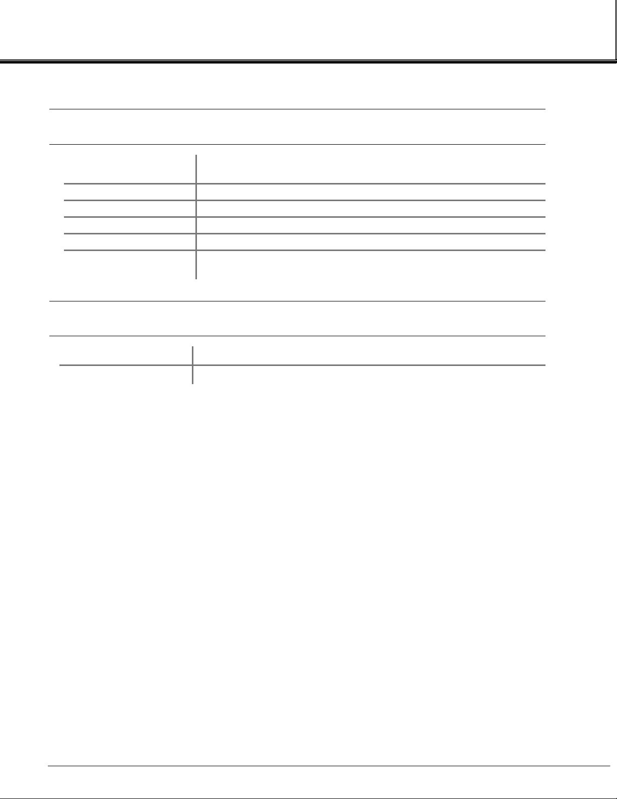
SPECIFICATIONS - GENERAL
M
EASUREMENT
S
PECIES
RANGES 0 to 100 ppm (output scalable down to 0-2 ppm fullscale)
A
CCURACY
SENSITIVITY <10 ppb Oxygen
NOISE 1% of fullscale, peak to peak
L
INEARITY
R
ESPONSE TIME
Z
ERO DRIFT
S
PAN DRIFT
E
FFECT OF
T
EMPERATURE
E
FFECT OF FLOW
O
PERATING
T
EMPERATURE
P
OWER REQUIREMENTS
Trace Oxygen
±3% of reading or ±0.02% of range (except for ranges ≤ 100
ppm: ±3% of reading or ±0.05% of range)
±1% of fullscale
Typically 90% in less than 20 seconds
≤±1% of fullscale/24 hours at constant temperature
≤±1% of fullscale/24 hours at constant temperature
0.32% of reading per °F from 70°F
(0.58% of reading per °C from 21°C)
≤2% of reading for a flow change of ±250 cc/min (0.5 SCFH)
32°F to 113°F (0°C to 45°C)
+24 VDC ±5%, 10 W max.
Ripple and Noise: <100 mV peak to peak
Line and Load Regulations: <±1%
PREFACE
SPECIFICATIONS - SAMPLE
S
AMPLE
F
LOW RATE
S
UPPLY PRESSURE
T
EMPERATURE
P
ARTICULATES
S
AMPLE HUMIDITY
748420-A
August 1999
Non-flammable (below 100% of the LEL)
0.5 to 1.5 L/min.
1027 to 1082 hPa - absolute (0.2 to 1.0 psig)
32°F to 113°F (0°C to 45°C)
filtered to <0.1 mg/L; non-condensing at ambient temperature
non-condensing at ambient temperatures
Trace Oxygen Analyzer Module
Rosemount Analytical NGA 2000
P5
PREFACE
SPECIFICATIONS - PHYSICAL
M
ATERIALS IN CONTACT
WITH SAMPLE
Stainless steel, Teflon, Delrin, neoprene
DIMENSIONS See Figure 2-2, Outline and Mounting Dimensions
W
EIGHT
M
OUNTING
C
ASE CLASSIFICATION
MAX. S
FROM
EPARATION
P
LATFORM
6.8 kg (15 lbs.)
Horizontal, external to Platform or custom installed in a panel
General Purpose for installation in weather protected area
1600 m (1 mile)
SPECIFICATIONS - GAS CONNECTIONS
S
AMPLE IN
S
AMPLE OUT
1/4 inch O.D. tube fitting
1/4 inch O.D. tube fitting
See the Preface Section of the Platform manual for specifications regarding Platform
related components.
Trace Oxygen Analyzer Module
P6
Rosemount Analytical NGA 2000
748420-A
August 1999

PREFACE
CUSTOMER SERVICE, TECHNICAL ASSISTANCE AND FIELD SERVICE
For order administration, replacement Parts, application assistance, on-site or factory
repair, service or maintenance contract information, contact:
Rosemount Analytical Inc.
Process Analytical Division
Customer Service Center
1-800-433-6076
RETURNING PARTS TO THE FACTORY
Before returning parts, contact the Customer Service Center and request a Returned
Materials Authorization (RMA) number. Please have the following information when you
call: Model Number, Serial Number, and Purchase Order Number or Sales Order Number.
Prior authorization by the factory must be obtained before returned materials will be
accepted. Unauthorized returns will be returned to the sender, freight collect.
When returning any product or component that has been exposed to a toxic, corrosive or
other hazardous material or used in such a hazardous environment, the user must attach
an appropriate Material Safety Data Sheet (M.S.D.S.) or a written certification that the
material has been decontaminated, disinfected and/or detoxified.
Return to:
Rosemount Analytical Inc.
4125 East La Palma Avenue
Anaheim, California 92807-1802
TRAINING
A comprehensive Factory Training Program of operator and service classes is available.
For a copy of the Current Operator and Service Training Schedule contact the Technical
Services Department at:
Rosemount Analytical Inc.
Phone: 1-714-986-7600
FAX: 1-714-577-8006
748420-A
August 1999
Trace Oxygen Analyzer Module
Rosemount Analytical NGA 2000
P7
PREFACE
DOCUMENTATION
The following Trace Oxygen Analyzer Module instruction materials are available. Contact
Customer Service or the local representative to order.
748420 Instruction Manual (this document)
COMPLIANCES
This product may carry approvals from several certifying agencies for use in nonhazardous, indoor locations. If so, the product will carry approval insignia on the product
name-rating plate.
®
Rosemount Analytical Inc. has satisfied all obligations from the European Legislation to
harmonize the product requirements in Europe.
These products comply with the standard level of NAMUR EMC. Recommendation (May
1993).
NAMUR
This product satisfies all obligations of all relevant standards of the EMC framework in
Australia and New Zealand.
96
N
Trace Oxygen Analyzer Module
P8
Rosemount Analytical NGA 2000
748420-A
August 1999

NTRODUCTION
I
1
1.1 O
This manual describes the Trace Oxygen (TO2) Analyzer Module of Rosemount Analytical's
NGA 2000 Series of gas analysis components.
The TO2 Analyzer Module is designed to continuously determine the concentration of trace
oxygen in a flowing gaseous mixture. The concentration is expressed in parts-per-million.
The TO2 Analyzer Module is configured as a shelf-mount module, designed to be installed
external from the platform on an associated shelf capable of holding two modules side-byside, with gas connections made from the rear. All electronics relative to sample detection
and conditioning are included in this module.
1.2 T
The TO2 Analyzer Module has specific applications in the following areas:
VERVIEW
YPICAL APPLICATIONS
Trace oxygen in product nitrogen and argon streams from air separation plants
•
Trace oxygen in inerting atmospheres for heat treat furnaces
•
Trace oxygen in glove-box applications
•
1.3 T
The TO2 Analyzer Module uses the coulometric principle of oxygen detection. This
technology is based on the fact that oxygen in the sample is reduced by an electrochemical
reaction. This reduction occurs at the cathode and results in the generation of hydroxyl
ions. These hydroxyl ions migrate to the anode where they are oxidized to reform oxygen.
The oxidation reaction generates four electrons which in turn migrate to the anode to
participate in the reduction reaction:
A polarizing voltage of approximately 1.3 VDC is applied between the anode and cathode
to drive the oxidation and reduction reactions. The resulting current flow produced by the
flow of electrons is directly proportional to the oxygen content in the sample gas.
HEORY OF TECHNOLOGY
(Cathode Reaction)
O2 + 2 H2O + 4 e- → 4 OH
(Anode Reaction)
4 OH- → O2 + 2 H2O + 4 e
-
-
748420-A
August 1999
Trace Oxygen Analyzer Module
Rosemount Analytical NGA 2000
1

NTRODUCTION
I
1
1.4 F
EATURES
Among the features included in the TO2 Analyzer Module are:
Quick start feature
•
Electrolyte level alarm
•
High oxygen protection circuit with alarm
•
Sample flow indication.
•
SECONDARY ANODE (+)
BI-STRATA™ DIFF USION
BARRIER
e
S
-
ELECTRONICS
IGURE
F
1-1. T
SAMPLE IN
KOH
SAMPLE OUT
SENSING CATHOD E (-)
O
2
SECONDARY CATHODE (-)
O
2
OH
S
-
RACE OXYGEN DETECTOR TECHNOLOGY
O
2
-
e
SENSING ANODE (- )
O
2
Trace Oxygen Analyzer Module
2
Rosemount Analytical NGA 2000
748420-A
August 1999

Network/Power
Module
NTRODUCTION
I
Sensor Assembly
Sensor
1
Computer
Board
Power Board
Sample Flow
Sensor
IGURE
F
748420-A
August 1999
1-2. T
RACE OXYGEN ANALYZER MODULE
OP VIEW
- T
Trace Oxygen Analyzer Module
Rosemount Analytical NGA 2000
3

NTRODUCTION
I
1
OTES
N
Trace Oxygen Analyzer Module
4
Rosemount Analytical NGA 2000
748420-A
August 1999

NSTALLATION
I
2
2.1 U
If the Trace Oxygen (TO2) Analyzer Module is received as a separate unit, carefully
examine the shipping carton and contents for signs of damage. Immediately notify the
shipping carrier if the carton or contents is damaged. Retain the carton and packing material
until all components associated with the TO2 Analyzer Module are operational.
2.2 A
Before installation of the TO2 Analyzer Module, electrolyte must be added to the Sensor.
Follow the procedure described below under section 2.2.1.
After addition of electrolyte, locate the analyzer module on an appropriate mounting surface
and connect the network cable to either the NETWORK 1 or NETWORK 2 connection on
the Analyzer Module, and the NETWORK connection on the Platform network I/O port. (See
Figures 2-1 and 2-4.)
2.2.1 E
Before adding electrolyte to the Sensor, it is recommended to check the Sensor for possible
leakage caused by damage in shipment. To check the Sensor for leakage, remove the top
cover of the Analyzer Module and locate and remove the 5 mounting screws which hold the
Sensor Assembly (Sensor, flow meter, plumbing, inlet/outlet fittings) to the module (see
Figure 4-2). Be careful not to lose these screws as they have metric threads. Carefully lift
out the Sensor assembly and remove from the analyzer module. Place on a flat surface and
remove the black Sensor cover by unscrewing counterclockwise.
NPACKING
SSEMBLY
LECTROLYTE ADDITION
Add distilled or deionized water to the Sensor to the maximum level indication on the
Sensor reservoir. Let Sensor stand for approximately 15 minutes and check for leaks
around the base of the reservoir, and at the seams and corners. If a leak is found, contact
the factory before proceeding. Drain the Sensor.
Fill the Sensor with one bottle of electrolyte supplied with the analyzer module. Use the
entire contents of the bottle.
748420-A
August 1999
Trace Oxygen Analyzer Module
Rosemount Analytical NGA 2000
5

2
NSTALLATION
I
Note
Do not add water. The volume and concentration of the bottled electrolyte is premeasured.
Reinstall the black Sensor cover and carefully reinstall the Sensor Assembly inside the
Analyzer Module. Do not the tilt the Sensor Assembly excessively as electrolyte may leak
out.
2.3 L
(See Figure 2.2) The TO2 Analyzer Module comes standard with mounting ears for easy
installation on flat, horizontal surfaces. Install the TO2 Analyzer Module in a clean, weatherproofed, vibration-free location free from extreme temperature variations and moisture. For
best results, install the instrument near the sample stream to minimize sample transport
time.
Operating ambient temperature is 0 °C to 45 °C (32 °F to 81 °F). Temperature change
should not exceed 10 °C (18 °F) per hour. The same temperature restrictions apply to the
location of the zero and span gas cylinders.
2.4 G
2.4.1 R
The TO2 Analyzer Module requires only a standard of accurately known composition for use
as a span gas. The span gas should be supplied from a cylinder equipped with a clean,
metallic diaphragm, two-stage regulator. A shutoff valve is recommen ded.
Calibration Gases
OCATION
ASES
EQUIREMENTS
The TO2 module does not require routine zero calibration. The zero is factory set and does
not experience routine drift. Over long periods of time, the zero may experience minor drift.
For low ppm range analyzers, you may wish to check the zero at one year intervals.
Oxygen-free nitrogen is recommended for use as zero gas. This gas is certified to <0.5
ppm oxygen and can be improved by passing the zero gas through an oxygen scrubber
such as Millipore™ W aferpure or Semigas Nanochem® re sin purifiers. A mixture of trace
oxygen in a background of nitrogen is recommended as span gas. For maximum accuracy,
the concentration of trace oxygen in the span gas should be as high as possible for the
range of measurement.
Trace Oxygen Analyzer Mod ul e
6
Rosemount Analytical NGA 2000
748420-A
August 1999

NSTALLATION
I
Sample
The sample must be clean and dry before entering the Analyzer Module. Sample should be
filtered for particulates down to two microns, and should have a dew point at least 5 °C (13
F) below the coldest expected ambient temperature.
°
Pressure
Constant between 13.8 and 69 hPa - gauge (0.2 and 1.0 psig) sample inlet pressure is
recommended. If a needle valve is used upstream of the Analyzer Module to control flow,
the inlet pressure to the needle valve should not exceed 345 hPa (5 psig). A constant
sample flow rate between 1.0 to 3.0 SCFH (0.5 to 1.5 l/min) is recommended for best
results. The Analyzer Module must vent to atmosphere to avoid back pressure influences
on the oxygen reading.
2
2.4.2 C
ONNECTIONS
(See Figure 2-3. ) Connect inlet and outlet lines for sample to appropriately labeled fittings
on the rear panel. SAMPLE IN and SAMPLE OUT are 1/4-inch ferrule-type compression
fittings. Zero and span gases should be introduced at the SAMPLE IN fitting at normal
sample inlet flow rate.
Metallic tubing is recommended for the samp le line. The use of plastic, Teflon, or other nonmetallic tubing can resu lt in ambient oxygen permeation throu gh the tubing causing h igher
than expected reading. Exhaust tubing should be 1/4 inch (6.3 mm) or larger, and can be
metallic or non-metallic.
ANALYZER MODULE
CONNECTIONS
Network 1
Network 2
Power
Backplane
Controller Board
Connector
BACKPLANE
CONNECTIONS
IGURE
F
748420-A
August 1999
2-1. A
Fuse
Power In dicator Light
Network
Power
NALYZER MODULE INTERCONNECTION WITH INSTRUMENT PLATFORM
Trace Oxygen Analyzer Module
Rosemount Analytical NGA 2000
7

2
NSTALLATION
[
]
2
]
I
18.56
471
12.00
[305]
.23
[6]
11.00
[279]
.266
[6.75]
DIA
7.75
[197]
7.75
[197]
1.61
[41]
.23
[6]
5.78
[147]
6.00
[152]
7.00
[178]
8.25
[206]
8.10
[206]
2.70
[68]
6.62
[168]
IGURE
F
Trace Oxygen Analyzer Mod ul e
8
Rosemount Analytical NGA 2000
2-2. O
UTLINE AND MOUNTING DIMENSIONS
10.15
[258]
.06
[1.5]
748420-A
August 1999
1.2
[31]
1.
[31

IGURE
F
2-3. B
ACK PANEL CONNECTIONS
NSTALLATION
I
Sample
Inlet
1/4" Tube
Sample
Exhaust
1/4" Tube
2
CAUTION: GAS OVERPRESSURE
At no time should sample, zero or span gas inlet pressure exceed 69 hPa gauge (1.0 psig). Damage to the Sensor may occur if this pressure level is
exceeded.
CAUTION: SAMPLE FLOW
Do not test the sample pressure by blocking the exhaust. When the pressure is
released the sudden surge of flow will spin the internal flowmeter off its
bearings and destroy it.
2.4.3 L
The TO2 Analyzer Module is completely tested at the factory for gas leakage. The user is
responsible for testing for leakage only at the inlet and outlet fittings on the rear panel.
EAK TEST
CAUTION: SENSOR DAMAGE
Do not expose the Sensor to pressure in excess of 1.0 psig as this may cause
damage.
748420-A
August 1999
Trace Oxygen Analyzer Module
Rosemount Analytical NGA 2000
9

2
NSTALLATION
I
Network Connections
Power Connection
Fuse
Power Indicator Light
IGURE
F
2.5 E
2-4. T
LECTRICAL CONNECTIONS
RACE OXYGEN ANALYZER FRONT PANEL
WARNING: ELECTRICAL SHOCK HAZARD
Operate this equipment only when covers are secured. Servicing requires
access to live parts which can cause death or serious injury. Refer servicing to
qualified personnel. For safety and proper performance, this module must be
connected to a properly grounded three-wire source of electrical power.
Electrical connections must be made in compliance with National Electrical
Code (ANSI/NFPA 70) and/or any applicable national or electrical codes.
Two electrical connections are required on the Analyzer Module: POWER and NETWORK
(See Figure 2-4). On the Analyzer Module, two NETWORK connectors are available, either
of which is appropriate for: 1) interconnection with the Backplane of the Platform or 2)
"daisy-chaining" with other NGA 2000 components (A star connection is acceptable for LON
lengths under about 10 meters.)
10
Connect a source of 24 V 5A DC power to the power inlet. Make sure that the ground
connection is made, and that this is separate from the power return lead. Failure to ensure
a good ground may result in random noise and disturbance in the analyzer readings.
Trace Oxygen Analyzer Mod ul e
Rosemount Analytical NGA 2000
748420-A
August 1999

TARTUP AND OPERATION
S
3
3.1 O
Prior to initial startup, the user should perform the leak test procedure outlined in Section 2
For the remainder of this section, Analyzer Module interconnection with a Platform or some
interfacing component will be a ssum ed. Disp lay and Ke ypad info rmatio n refe rs to tha t which
the user can expect to see and do with regard to the Front Panel of the Platform.
(For a complete description of Platform Front Panel controls and indicators, see the Platform
instruction manual
3.2 D
Three kinds of Display screens are available to the user:
VERVIEW
ISPLAYS
Run Mode
•
Menu
•
Help
•
3.2.1 R
The Run Mode is the normal mode of operation. In this mode, the Display will show the
current gas measurement, the component of interest, the current operations of the softkeys,
and several graphics: a bar representing the displayed concentration as a percent of
fullscale and up to four lines showing user selectable secondary parameters from either the
Analyzer Module or any IO module bound to it. See the Platform manual for information as
to how to select these.
If more than one Analyzer Module is connected to the system, an additional Run Mode
display will show as many as four (five for version 2.3 and later) gas measurements on
screen.
748420-A
August 1999
UN MODE DISPLAY
Trace Oxygen Analyzer Module
Rosemount Analytical NGA 2000
11

3
TARTUP AND OPERATION
S
TO2 1
2
50
IGURE
F
3.2.2 M
3-1. R
UN MODE DISPLAY
ENU DISPLAYS
19.4
0 Range 3
Sensor current: 1.4403 mA
Sensor temperature: 26.3 C
Temperature current: 2.01 mA
Sample Flow: 511 ml/min
DISPLAY PARMS. MENU NEXT INFO
ppm O
The Menu structure enables the user to access data and functions, and put information onto
the network. From the Run Mode display, press the MENUS softkey to gain access to the
Main Menu.
Main Menu
Basic controls . . .
Expert controls and set up . . .
(Operational configuration)
Technical level configuration . . .
(Diagnostic and manufacturing/service)
DISPLAY PARMS. NEXT EXT LOCK INFO
IGURE
F
3-2. M
AIN MENU
The Main Menu is subdivided into three levels of control based generally on which
personnel is likely to use it:
Engineers, and
Technical level configuration
Basic Controls
- Operators,
Expert Controls and set up
- Analyzer technicians. Many layers of the
menu structure are described at appropriate places throughout this manual.
From the Run Mode display, press the MENUS softkey to gain access to the Main Menu.
Trace Oxygen Analyzer Mod ul e
12
Rosemount Analytical NGA 2000
- System
748420-A
August 1999
 Loading...