

Manual: NGA 2000 TFID Hydrocarbon Analyzer Module SW 3.7 Supplement to SW 3.4 Software-1st Ed. | Rosemount
Table of contents
 Loading...
Rosemount Manual: NGA 2000 TFID Hydrocarbon Analyzer Module SW 3.7 Supplement to SW 3.4 Software-1st Ed. | Rosemount Manuals & Guides
Instruction Manual
HAS55E03IM11S
11/2003
Software Version 3.7.x
Supplement to Software Manual 3.4.x
NGA 2000 Software Manual for
TFID Analyzer and Analyzer Module (combined with
NGA 2000 Platform, MLT, CAT 200 or TFID Analyzer)
www.EmersonProcess.de

TFID Software 3.7.x Instruction Manual
HAS55E03IM11S
11/2003
ESSENTIAL INSTRUCTIONS
READ THIS P AGE BEFORE PROCEEDING!
Emerson Process Management (Rosemount Analytical) designs, manufactures and test s
its products to meet many national and international standards. Because these instruments
are sophisticated technical products, you MUST properly install, use, and maintain
them to ensure they continue to operate within their normal specifications. The following
instructions MUST be adhered to and integrated into your safety program when installing,
using and maintaining Emerson Process Management (Rosemount Analytical) products.
Failure to follow the proper instructions may cause any one of the following situations to
occur: Loss of life; personal injury; property damage; damage to this instrument; and warranty
invalidation.
• Read all instructions prior to installing, operating, and servicing the product.
• If you do not understand any of the instructions, contact your Emerson Process
Management (Rosemount Analytical) representative for clarification.
• Follow all warnings, cautions, and instructions marked on and supplied with the product.
• Inform and educate your personnel in the proper installation, operation, and
maintenance of the product.
• Install your equipment as specified in the Installation Instructions of the appropriate
Instruction Manual and per applicable local and national codes. Connect all products
to the proper electrical and pressure sources.
• T o ensure proper performance, use qualified personnel to install, operate, update, program,
and maintain the product.
• When replacement parts are required, ensure that qualified people use replacement parts
specified by Emerson Process Management (Rosemount Analytical). Unauthorized parts
and procedures can affect the product’s performance, place the safe operation of your
process at risk, and VOID YOUR W ARRANTY. Look-alike substitutions may result in fire,
electrical hazards, or improper operation.
• Ensure that all equipment doors are closed and protective covers are in place, except
when maintenance is being performed by qualified persons, to prevent electrical
shock and personal injury.
The information contained in this document is subject to change without notice. Misprints
reserved.
1st Edition 1 1/2003 (Addendum to TFID Software 3.4.x)
© 2006 by Emerson Process Management
Emerson Process Management
GmbH & Co. OHG
Industriestrasse 1
D-63594 Hasselroth
Germany
T +49 (0) 6055 884-0
F +49 (0) 6055 884-209
Internet: www.EmersonProcess.com

Software 3.7.x – Supplement to Software 3.4.x and 3.6.x
Table of Contents
A Addendum from Software 3.4.x to 3.6.x
1 Display Controls Menus ………………………………………………………………A-1
2 Analyzer Basic Controls (calibration) & Setup Menu………………………………A-3
3 Tolerances Menus……………………………………………………………………..A-4
B Addendum from Software 3.6.x to 3.7.x
4 Calculator on Control Module Level ………………………….…………….Page 1 -14
5 Programmable Logic Control (PLC) on Control Module Level……….….Page 1 - 28
6 System Calibration - Software Version 3.7.x………………………Supplement 1 - 34
7 Additional AK Protocol Commands - Software Version 3.7.x …..…….……Page 1-3
HAS55E03IM11S(1) [NGA-e (TFID Software 3.7.x)] 11/03 Content I

Software 3.7.x – Supplement to Software 3.4.x and 3.6.x
II Content HAS55E03IM11S(1) [NGA-e (TFID Software 3.7.x)] 11/03
Addendum for Software Revision 3.6.x to 3.4.x
This chapter describes some important features / changes
implemented in software revision 3.6.x, shipped with the newest
versions of Fisher-Rosemount NGA gas analyzers and has to be
used in combination with the software 3.4.x manual.
1. Display Controls Menu
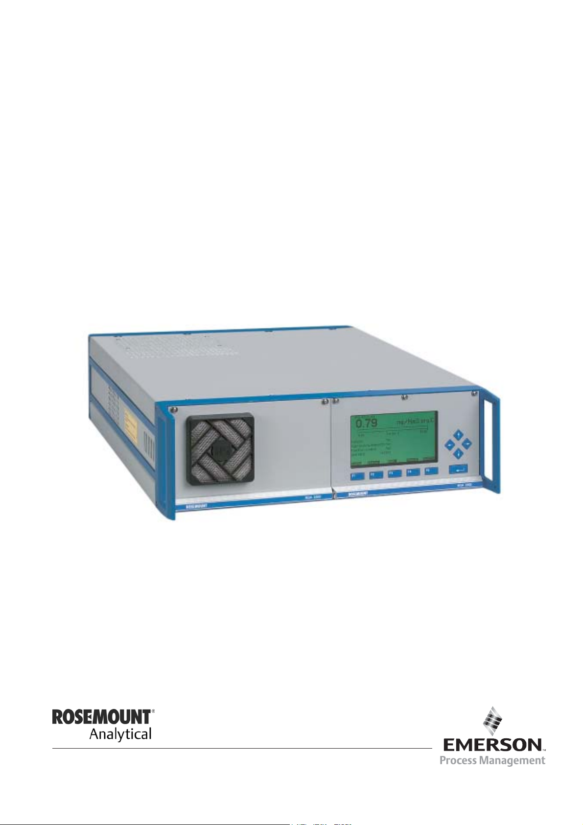
The Display Controls menu (see chapter 7) now has additional menu lines:
Setting parameters:
TAG
-- Display Controls --
Brightness:
Contrast:
Display measurement menu after: 10 Min
Default measurement menu:
Switch off backlight after:
Measure
F1
Single component
F2
F3 F4 F5
Back... More...
37.50 ppm
74 %
23 %
10 Min
♦ Select any line of variables using the ↓ -key or the ↑ -key.
♦ Select the variable using the ↵ -key or the → -key.
♦ Change the whole value using the ↑ -key or the ↓ -key
or select single digits using the ← -key or the → -key and enter a new value using
the ↑ -key or the ↓ -key.
♦ Confirm the new value using the ↵ -key or
cancel and return to the previous value using the F2 -key.
Line of variables "Display measurement menu after:"
The value entered in this line defines the time to expire without operator input before the display
automatically returns to the measurement display.
Options: 10 s, 30 s, 1 min, 5 min, 10 min, 30 min, Never.
HAS55E03IM11S [NGA-e (TFID Software 3.4.X addendum)] 11/03
NGA 2000
A - 1

Line of variables "Default measurement menu:"
Use this line to select the display the analyzer returns to when the time entered in line “display
measurement menu after:” has expired.
Options: Single Component (Display) or Multi Component (Display)
Line of variables "Switch off backlight after:"
The value entered in this line defines the time to expire without operator input before the
backlight is switched off automatically. Using this function saves energy and expands the
backlight’s lifetime.
Options: 10 s, 30 s, 1 min, 5 min, 10 min, 30 min, Never.
A - 2
NGA 2000
HAS55E03IM11S [NGA-e (TFID Software 3.4.X addendum)] 11/03

Addendum for Software Revision 3.6.x to 3.4.x
2. Analyzer Basic Controls (calibration) & Setup Menu
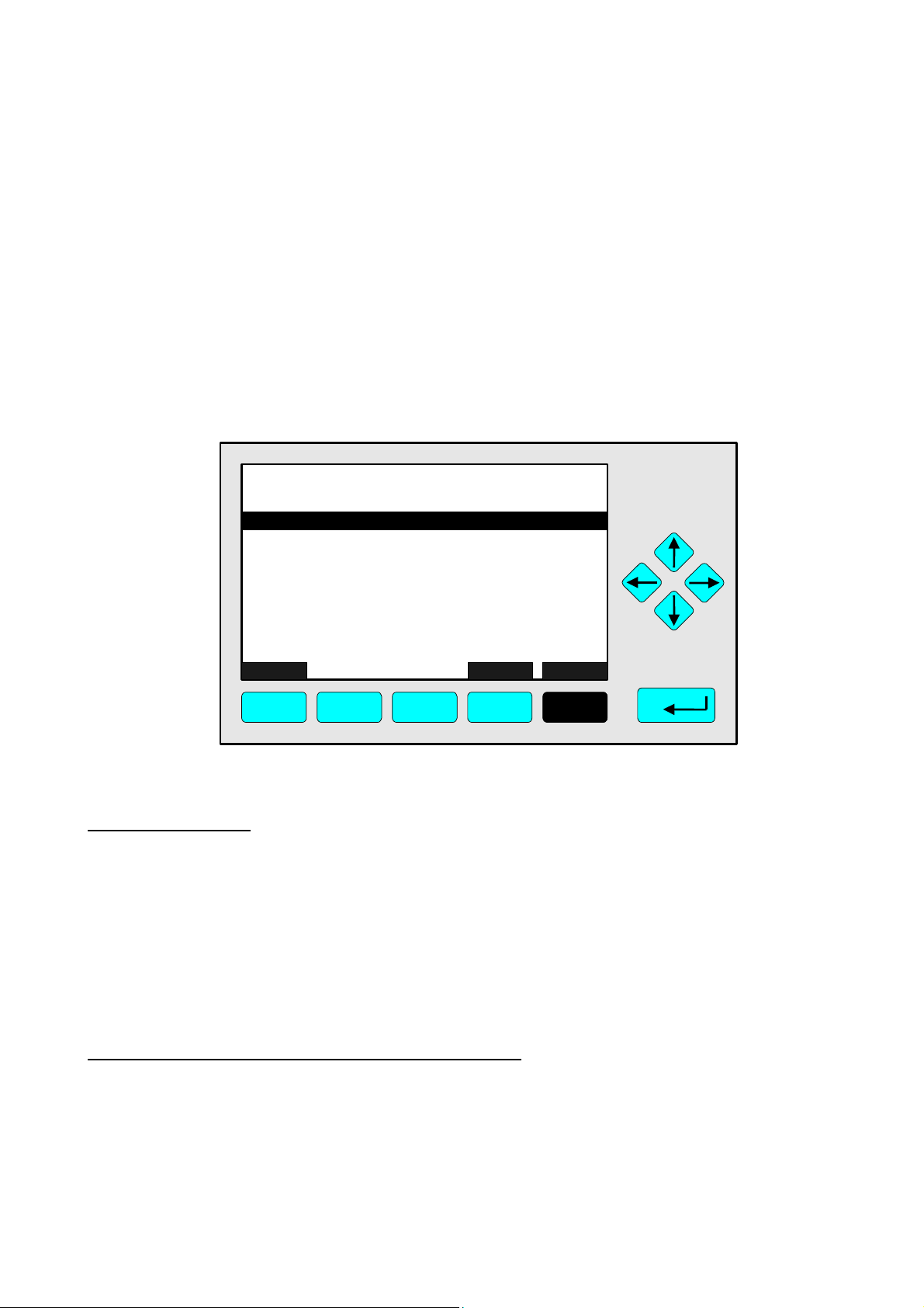
One line was added to this menu (see chapter 4.4, p. 4-19):
Function Line "Undo last zero & span calibration !"
TAG
-- Analyzer Basic Controls (calibration) & Setup --
Calibration procedure state..
Start zero calibration procedure !
Start span calibration procedure !
Check calibration deviation:
Undo last zero & span calibration !
Range number:
Span gas:
Range upper limit:
Operation status:
Measure Status... Channel Back...
F1 F2 F3 F4 F5
37.50 ppm
Disabled
1
46.00 ppm
50.00 ppm
Ready
Valves...
Use this function to reset an analyzer’s calibration values to default factory settings if the last
calibration procedure has been completed with a poor result due to wrong settings and the
calibration is in an undefined status.
Depend on the “Measurement Display Configuration” settings a screen may appear asking for
confirmation prior to executing the function (see chapter 3.7, p. 3-6 and chapter 5.1.8,
p. 5-49).
HAS55E03IM11S [NGA-e (TFID Software 3.4.X addendum)] 11/03
NGA 2000
A - 3
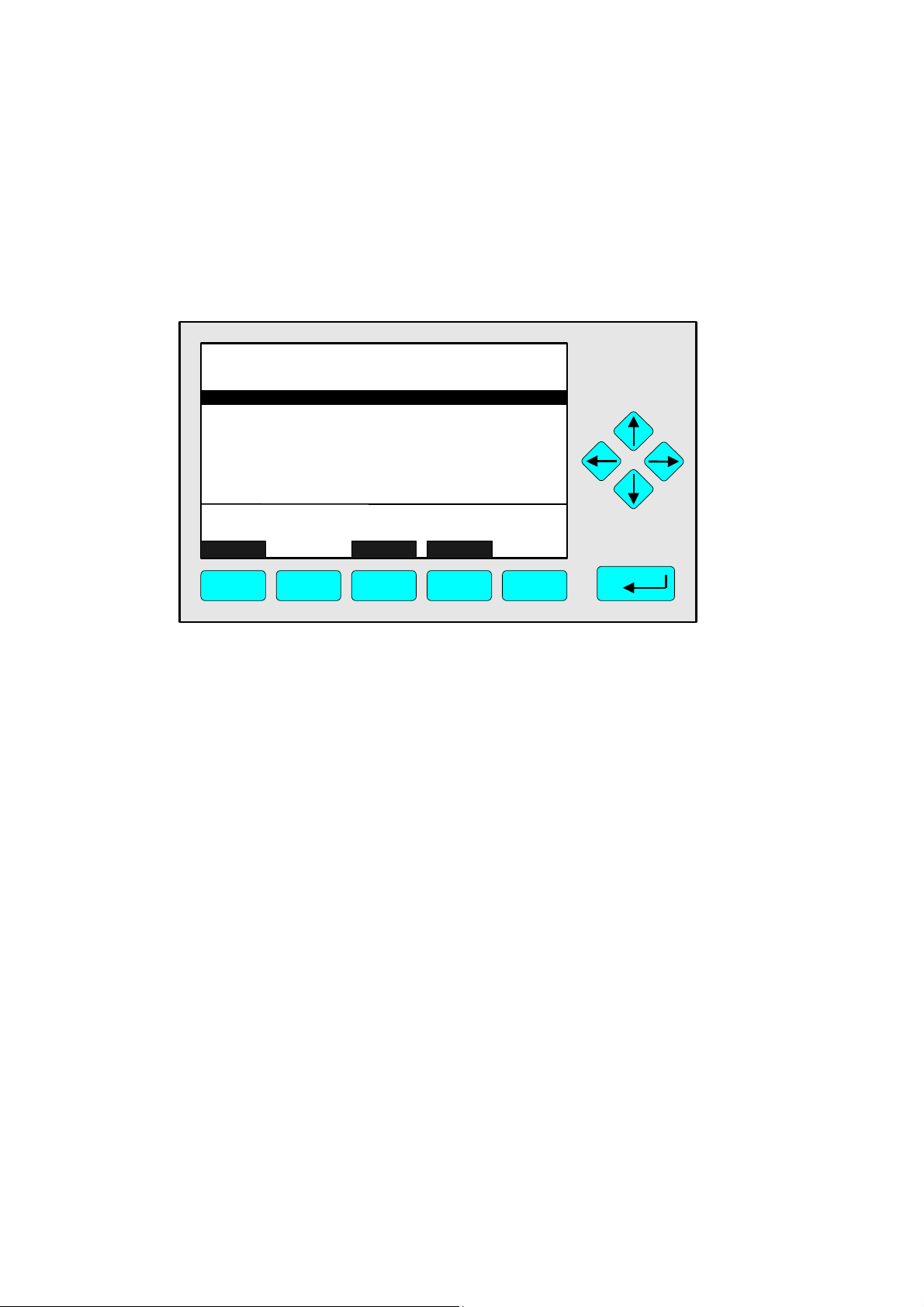
3. Tolerances Menu
The stability tolerance range 1 … 4 lines of the menu Tolerances (see chapter 5.1, p. 5-8) have
been moved into a new menu within the service level:
The stability tolerance function is still enabled but not longer operator definable.
Factory setting for all 4 values (ranges 1 … 4) is 10 %.
TAG
-- Tolerances --
Max. zero calibration deviation: 20.00 %
Max. span calibration deviation: 20.00 %
Check calibration deviation:
Last zero calibration:
Last span calibration:
Measure Channel Back...
F1 F2 F3 F4 F5
95.00 ppm
Disabled
Success
Success
A - 4
NGA 2000
HAS55E03IM11S [NGA-e (TFID Software 3.4.X addendum)] 11/03

Calculator on Control Module Level
Calculator on Control Module Level
(Platform, TFID, MLT or CAT 200 Analyzer)
1 SYSTEM CALCULATOR (ON CONTROL MODULE LEVEL)........................................................................2
1.1 P
1.2 L
1.3 CONSTANT VALUES......................................................................................................................................5
1.4 M
1.5 MENU TREE FOR THE SYSTEM CALCULATOR ..................................................................................................6
2 DISPLAY CALCULATOR RESULTS ON MINI-BARGRAPH.......................................................................11
2.1 D
2.2 A
3 ASSIGNMENT TO SIO ANALOG OUTPUTS ...............................................................................................14
RINCIPLE OF PROGRAM SET-UP ..................................................................................................................2
IVE VALUES (REAL MEASURING VALUES) ......................................................................................................4
EMORY VALUES.........................................................................................................................................5
1.5.1 Submenu 'Signals' .................................................................................................................................7
1.5.2 Submenu 'Programming' .......................................................................................................................9
ISPLAY MODE ..........................................................................................................................................11
SSIGN SIGNALS AND CONVENIENT NAMES ..................................................................................................12
PICTURE 1-1: SYSTEM CALCULATOR MENU.................................................................................................................6
P
ICTURE 1-2 : SIGNAL ASSIGNMENT OF SYSTEM CALCULATOR ....................................................................................7
PICTURE 1-4: CONSTANT VALUES ASSIGNMENT ..........................................................................................................9
PICTURE 1-5: PROGRAMMING THE SYSTEM CALCULATOR ..........................................................................................10
P
ICTURE 2-1: MEASUREMENT DISPLAY SET-UP.........................................................................................................11
PICTURE 2-2: PLATFORM SELECTED SIGNAL ASSIGNMENT .........................................................................................12
PICTURE 2-3: LISTING OF ASSIGNED SIGNALS............................................................................................................13
TABLE 1-1: THE OPERATORS OF THE SYSTEM CALCULATOR ........................................................................................3
TABLE 1-2: LIVE VALUES POOL...................................................................................................................................4
HAS55E03IM11S(1) [NGA-e (TFID software 3.7.x)] CM Calculator Page 1

Calculator on Control Module Level
1 System Calculator (on Control Module Level)
1.1 Principle of program set-up
As it would be a too high effort to realize a comfortable mathematical formula system we created a syntax which
is easy to input and easy to realize.
As we assume that customers or service people have to set-up the program only one times for an installed
system it should be acceptable to realize a form which is only done by inputting numbers.
Therefore we have mainly to differ between positive and negative numbers.
The program operations are assigned with negative numbers.
The operands which are used by these input operations are positive numbers. These positive numbers
symbolize signals which are part of a signal pool.
Also we have to know that there are used different classes of operands. That means we have different
classes of signal pools.
Those are:
• Live values (real measuring values)
• Constant values
• Memory values.
In each of these classes exists an own numbering and we determine by the operator itself which class of these
operands is meant.
Remark:
Opposite to former versions allowing calculator function within ONE TFID/MLT/CAT 200 analyzer module (AM)
or for ONE TFID/MLT analyzer (or CAT 200 analyzer resp.) ONLY now the system calculator is based on the
C
ontrol Module level (CM).
This allows to include ALL analyzer modules resp. MLT channels of a NGA 2000 analyzer system into the
calculation.
The results of the system calculator can be put onto the 2-8 analog outputs of the programmable Input/Output
Module SIO.
The SIO as a Control Module I/O is then located in a platform or in a TFID, MLT or CAT 200 Analyzer.
HAS55E03IM11S(1) [NGA-e (TFID software 3.7.x)] CM Calculator Page 2

Calculator on Control Module Level
In the following table we find all the currently available operators (negative numbers) and their meaning. Hereby
is used the acronym "IR" for the actually calculated intermediate result of the program.
Table 1-1: The Operators of the System Calculator
Operator
number
-10 SUBM m subtract following memory value operand from IR (IR = IR – m)
-11 DIVM m divide IR by following memory value operand (IR = IR / m)
-12 MULM m multiply IR with following memory value operand (IR = IR * m)
-13 STOM m store IR at following memory value and set IR = 0.0 (m = IR; IR = 0)
-14 STOR r store IR to following result and set IR = 0.0 ( r = IR; IR = 0)
-15 NOP no operation (placeholder)
-16 ABS convert IR into absolute value (IR = |IR|)
-17 EOP end of program
-18 SQRT
-19 NEG negate IR (IR = -IR)
-20 INC increment IR (IR = IR + 1)
-21 DEC decrement IR (IR = IR – 1)
-22 INV invert IR (IR = 1 / IR)
-23 EXP exponential function (IR = eIR)
-24 POWM IR raised to the power of the following memory value operand
-25 IF> m1 m2 m3 if IR > 1st following memory value
-26 IF< m1 m2 m3 if IR < 1st following memory value
-27 IF= m1 m2 m3 if IR = 1st following memory value
-28 LN natural logarithm (IR = ln(IR))
-29 LOG base 10 logarithm (IR = log(IR))
Acronym Description
-1 ADD l add following live value operand to the IR (IR = IR + l)
-2 SUB l subtract following live value operand from IR (IR = IR – l)
-3 DIV l divide IR by following live value operand (IR = IR / l)
-4 MUL l multiply IR with following live value operand (IR = IR * l)
-5 ADDC c add following constant value operand to the IR (IR = IR + c)
-6 SUBC c subtract following constant value operand from IR (IR = IR – c)
-7 DIVC c divide IR by following constant value operand (IR = IR / c)
-8 MULC c multiply IR with following constant value operand (IR = IR * c)
-9 ADDM m add following memory value operand to the IR (IR = IR + m)
build square root of IR (IR = √IR)
(IR = IR
then IR = 2
else IR = 3
then IR = 2
else IR = 3
then IR = 2
else IR = 3
m
)
nd
following memory value
rd
following memory value
nd
following memory value
rd
following memory value
nd
following memory value
rd
following memory value
HAS55E03IM11S(1) [NGA-e (TFID software 3.7.x)] CM Calculator Page 3

Calculator on Control Module Level
1.2 Live values (real measuring values)
In the platform calculator we have a signal pool of momentary up to 25 possible live signals.
The first 10 signals in this pool are fix assigned the rest of the signals are free assignable.
Table 1-2: Live Values Pool
Number Assignment assignment type
Signal 1 Result 1 fixed
Signal 2 Result 2 fixed
Signal 3 Result 3 fixed
Signal 4 Result 4 fixed
Signal 5 reserved fixed
Signal 6 reserved fixed
Signal 7 reserved fixed
Signal 8 reserved fixed
Signal 9 reserved fixed
Signal 10 reserved fixed
Signal 11 MLT 1/CH1 Concentration programmable
Signal 12 TFID Concentration programmable
Signal 13 MLT 2/CH3 Temperature programmable
Signal 14 TFID Temperature programmable
Signal 15 not assigned programmable
.... ........... programmable
Signal 25 not assigned programmable
By using these numbers of the signal pool we determine the live value operands in the calculator's program.
Example of a calculator program with upper signal assignment:
Result 1 = (MLT 1/CH1 Concentration) + (TFID Concentration)
Step (o+1) -1 ADD (at beginning the intermediate result IR = 0)
Step (o+2) 11 Signal 11 (here: MLT1/CH1 Concentration)
Step (o+3) -1 ADD
Step (o+4) 12 Signal 12 (here: TFID Concentration)
Step (o+5) -14 Store IR to result
Step (o+6) 1 Result 1
Step (o+7) -17 End of program
HAS55E03IM11S(1) [NGA-e (TFID software 3.7.x)] CM Calculator Page 4

Calculator on Control Module Level
1.3 Constant values
The same principle is used for the constant values. We have a pool of free assignable constant values.
Example of a constant signal pool:
Number Assignment
Constant-1 1.000000
Constant-2 10.00000
Constant-3 100.0000
Constant-4 1000.000
Constant-5 10000.00
.... ...........
Constant-21 500.0000
By using the numbers of the signal pool we determine again the constant operands in the calculator's program.
Example of a calculator program with upper live signal and constant assignment:
Result1 = (MLT 1/CH1-Concentration) + 100
Step (o+1) -1 ADD (addition by using the live operand's class)
Step (o+2) 11 Live value number 11 (here: MLT1/CH1-Concentration)
Step (o+3) -5 ADDC (addition by using the constant operand's class)
Step (o+4) 3 Constant number 3 (here: 100.0)
Step (o+5) -14 Store IR to result
Step (o+6) 1 Result 1
Step (o+7) -17 End of program
1.4 Memory values
The same principle as in constant values is used again for the memory values. We have a pool of usable
memory places where intermediate calculation results can be stored to.
HAS55E03IM11S(1) [NGA-e (TFID software 3.7.x)] CM Calculator Page 5

Calculator on Control Module Level
1.5 Menu tree for the system calculator
The following pictures show the menu tree and the LON variables which are assigned to the single menu lines.
System configuration and diagnostics...
↓
System calculator...
↓
- System calculator-
Programming...
Signals...
Units...
Scaling...
Calculator is: Enabled
Program error in step: 0
Result Calculator 1: 0.1234
Result Calculator 2: 1234.5
Result Calculator 3: 123.45
Result Calculator 4: 98.765
Picture 1-1: System Calculator Menu
With the 'Calculator is' parameter we show whether the system calculator functionality is
• Disabled
• Enabled
• has a Program Error (after trying to enable)
In the case of a program error by the 'Program error in step:' parameter is displayed in what step of the program
this error happened. If there is no error this parameter equals '0'.
CALCSTATUS
CLCERRLINE
CALC1RESULT
CALC2RESULT
CALC3RESULT
CALC4RESULT
HAS55E03IM11S(1) [NGA-e (TFID software 3.7.x)] CM Calculator Page 6

Calculator on Control Module Level
1.5.1 Submenu 'Signals'
The live values' signal assignment is done in the submenu 'Signals...".
System configuration and diagnostics...
↓
System calculator...
↓
Signals...
↓
- Signals -
Signal number: 11
Choose signal source module...
Choose signal...
Signal name: Concentration
Signal comes from: MLT/CH1
Current signal value: 123.45 ppm
View...
Picture 1-2 : Signal Assignment of System Calculator
CALCSIGNUMC
CALCSRCSEL_
CALCSIGSEL_
CALCSIGC
CALCSRCC
CALCVALC
fct3: CASIGLST_
The single signals of the pool (selected by 'Signal number') are assigned by first selecting the source analyzer
module (AM) resp. analyzer channel of the requested signal and then the signal name itself.
Please, note that is only possible to modify the programmable type of signal numbers.
To realize the signal name's selection there is used an already implemented feature of the AMs. It has being
used for the small bar graphs display and for the analog outputs of the SIO module. It is the SVCONT/SVNAME
variable mechanism. This mechanism provides the possibility to have a link to the LON variables of an AM
which are listed in the SVCONT enum. In the SVNAME variable are listed the related human readable strings.
If we want to assign the signals not via the menu but via LON variable access we have to do the following steps:
1. Enter signal number by setting CALCSIGNUMC.
2. Enter the source of the signal by setting CALCSRCC to the TAG-variable's string of the requested channel.
3. Set CALC_ENTRYSIG (instead of using CALCSIGC) to the enum value that the signal has in the SVCONT-
variable.
HAS55E03IM11S(1) [NGA-e (TFID software 3.7.x)] CM Calculator Page 7

Calculator on Control Module Level
It is possible to show a listing of the whole signal pool with the entered programmable as well as the fixed
assignments.
-- Signal List --
List offset: 10
Signal (o+1): Concentration: MLT/CH1
Signal (o+2): Concentration: MLT/CH2
Signal (o+3): Concentration: MLT/CH3
Signal (o+4): Concentration: TFID
Signal (o+5): Temperature: MLT/CH1
Signal (o+6): Temperature: MLT/CH2
Signal (o+7): Pressure: MLT/CH1
Signal (o+8): Flow: MLT/CH3
Signal (o+9): ????: ????
Signal (o+10): ????: ????
<< Back... >>
Picture 1-3: Listing of Signal Assignment
LISTOFFSET
MENU1LINE
MENU2LINE
MENU3LINE
MENU4LINE
MENU5LINE
MENU6LINE
MENU7LINE
MENU8LINE
MENU9LINE
MENU10LINE
fct3: BACKVARS
fct4: ESCAPE
fct5: LOADVARS
HAS55E03IM11S(1) [NGA-e (TFID software 3.7.x)] CM Calculator Page 8

Calculator on Control Module Level
1.5.2 Submenu 'Programming'
The constant values are configured in the submenu 'Programming...".
System configuration and diagnostics...
↓
System calculator...
↓
Programming...
↓
- Constants (1/3) -
Constant -1: 1.000000
Constant –2: 10.00000
Constant –3: 100.0000
Constant –4: 1000.000
Constant –5: 10000.00
Constant –6: 100000.0
Constant –6: 1000000
Programming...
More...
Picture 1-4: Constant Values Assignment
CALCAC1
CALCAC2
CALCAC3
CALCAC4
CALCAC5
CALCAC6
CALCAC7
CALCPRG_
fct5: CALCCONS2
System configuration and diagnostics...
↓
System calculator...
↓
Programming...
↓
More...
↓
- Constants (2/3) -
Constant –8: 0.100000
Constant –9: 0.010000
Constant –10: 0.001000
Constant –11: 0.000100
Constant –12: 0.000010
Constant –13: 0.000001
Constant –14: 0.200000
More...
CALCBC1
CALCBC2
CALCBC3
CALCBC4
CALCBC5
CALCBC6
CALCBC7
fct5: CALCCONS3
HAS55E03IM11S(1) [NGA-e (TFID software 3.7.x)] CM Calculator Page 9

Calculator on Control Module Level
After having done the set-up of the signals we can do the programming of Calculator algorithm itself. It is done
in the submenu 'Programming...".
System configuration and diagnostics...
↓
System calculator...
↓
Programming...
↓
Programming...
↓
-- Programming --
Program offset (o): 0
Step (o+1): -2
Step (o+2): 67
Step (o+3): -4
Step (o+4): -3
Step (o+5): 37
Step (o+6): -8
Step (o+7): 1
Step (o+8): -7
Step (o+9): 0
Step (o+10): 0
<< Back... >>
Picture 1-5: Programming the System Calculator
If we want to assign the signals not via the menu but via LON variable access we have to be aware of following:
1. The PLC-programming as well as the programming for the system calculator happens indirectly via the edit
variable-array ED_INTx.
To differ what the programming is for there exists the LON variable PROGTYP.
Setting PROGTYP = 0 means we want to program the system calculator.
Setting PROGTYP = 1 means we want to program the system PLC.
2. By using the variable LISTOFFSET we determine what part of the whole programming list we want to
program.
For example, setting LISTOFFSET = 60, means by usage of ED_INT1...ED_INT10 we are able to modify
the program steps 61...70.
LISTOFFSET
ED_INT1
ED_INT2
ED_INT3
ED_INT4
ED_INT5
ED_INT6
ED_INT7
ED_INT8
ED_INT9
ED_INT0
fct3: BACKVARS
fct4: ESCAPE
fct5: LOADVARS
HAS55E03IM11S(1) [NGA-e (TFID software 3.7.x)] CM Calculator Page 10

Calculator on Control Module Level
2 Display Calculator Results on Mini-bargraph
In order to show the calculator results on the mini-bargraphs of the single component display we overworked the
architecture of the bargraph displays.
All the signals which are shown on this display in the versions up to now belonged always to the selected
component, that means they belonged all to the same AM-channel or to an I/O module which is bound to it.
To show a calculator result which belongs to the CM we have to assign signals of a different node/subnode
to the single component display's bargraphs. Therefore we have chosen a way which enables us to do a
complete free signal assignment.
Also we are able to set-up the calculator result's unit and its range limits.
And finally we are able to assign an own signal name to the bar graphs. Up to now there have been shown the
name that is noticed in the SVNAME variable. For most of signals this is sufficient. But especially for signals
which have no unique function (like calculator results) we want to show configurable and therefore more intuitive
signal names.
By inventing this new bargraphs display structure we also looked to have a behavior which can fulfill the current
functionalities.
Therefore we created the possibility to assign signals of I/O modules and their implemented SVCONT/SVNAME
signals as well as the ANALOGOUTPUT/ANOPUNITS variable of older I/O module versions.
2.1 Display mode
For each selectable component we can compose bar graph displays. This composition can show signals of a
prepared pool from any attached network node.
To have the possibility of being compatible to current software versions we create also a mode which displays
the signals as they are selected by the analyzers itself.
System configuration and diagnostics...
↓
Measurement display set-up...
↓
-- Measurement display set-up (1/2)--
Choose component module...
Selected component module: MLT/CH1
Display mode for line 1: Disabled
Display mode for line 2: AnalyzerSelected
Display mode for line 3: PlatformSelected
Display mode for line 4: PlatformSelected
Signal number for line 1: 1
Signal number for line 2: 1
Signal number for line 3: 2
Signal number for line 4: 4
Signals
Picture 2-1: Measurement Display Set-up
LINSRCSEL_
LINESRCMODC
LINEDISPC1
LINEDISPC2
LINEDISPC3
LINEDISPC4
LINESIGNC1
LINESIGNC2
LINESIGNC3
LINESIGNC4
In upper menu we first select the component we want to do the assignment for ("Choose component
module...").
HAS55E03IM11S(1) [NGA-e (TFID software 3.7.x)] CM Calculator Page 11

Calculator on Control Module Level
By use of the four "Display mode for line x"-parameters we select the handling of the 4 bar graphs.
Disabled: The bar graph is switched off.
AnalyzerSelected: The bar graph receives the signal from the SVNAMEx-variable of the selected component
module (AM). This is the already implemented and mainly used mode.
PlatformSelected: The bar graph receives its signal from a signal pool that is installed in the Control Module
itself.
2.2 Assign signals and convenient names
If we use the 'PlatformSelected' signal mode we have to determine what signal number of the pool has to be
displayed. The selection of this number is performed in the appropriate menu line "Signal number for line x".
Now we have to determine only what kind of signal is behind each signal number of the pool.
This is done in the following menu display.
System configuration and diagnostics...
↓
Measurement display set-up...
↓
Signals...
↓
- Assign mini-bargraph signals -
Signal number: 4
Choose signal source module...
Choose signal...
Signal description: NOx-Calculation
Signal comes from: Control Module
Signal name: Sys.-calculator 1
View...
Picture 2-2: Platform selected Signal Assignment
SGNSNUMC
AUXSRCSEL_
AUXSIGSEL_
SGNDESCRC
SGNSRCMODC
SGNSRCSIGC
fct3: AUXLIST_
We are able to assign signals which come from all installed nodes/subnodes and have the SVCONT/SVNAME
variable. Further more we present I/O modules which have the ANALOGOUTPUT / ANOPUNITS variable.
The procedure is the following:
First we select the signal number we want to assign the signal for.
Then we choose the source (node/subnode) the signal shall come from.
After this we choose the signal itself of the selected source.
With the "Signal description" parameter, which is an editable string variable, we create the ability to give a
convenient signal name to each of the assigned signals.
If we want to assign this not via the menu but via LON variable access we have to do the following steps:
1. Enter signal number by setting SGNSNUMC.
2. Enter the source of the signal by setting SGNSRCMODC to the TAG variable's string of the requested
channel.
3. Set SGN_ENTRYSIG (instead of using SGNSRCSIGC) to the enum value that the signal has in the
SVCONT variable.
4. Enter the signal description by setting SGNDESCRC.
HAS55E03IM11S(1) [NGA-e (TFID software 3.7.x)] CM Calculator Page 12

Calculator on Control Module Level
A complete overview of the signals in the pool can be obtained then in the following menu.
System configuration and diagnostics...
↓
Measurement display set-up...
↓
Signals...
↓
View...
↓
- Signal List Signal offset (o): 0
Signal 1+o: Sys.-calculator 1: Control Module
Description: Sum of CO and CO2
Signal 2+o: Sys.-calculator 2: Control Module
Description: SysCalc2
Signal 3+o: Sys.-calculator 3: Control Module
Description: SysCalc3
Signal 4+o: Sys.-calculator 4: Control Module
Description: SysCalc4
Signal 5+o: ????: ????
Description: ????
<< Back... >>
Picture 2-3: Listing of assigned Signals
LISTOFFSET
MENU1LINE
MENU2LINE
MENU3LINE
MENU4LINE
MENU5LINE
MENU6LINE
MENU7LINE
MENU8LINE
MENU9LINE
MENU10LINE
fct3: BACKVARS
fct4: ESCAPE
fct5: LOADVARS
HAS55E03IM11S(1) [NGA-e (TFID software 3.7.x)] CM Calculator Page 13

Calculator on Control Module Level
3 Assignment to SIO Analog Outputs
The assignment of the system calculator results to an analog output of the SIO board is realized by extending
the selectable module types. Now it is also possible to select the platform itself with its own signals (calculator
results).
That means we have added the SVCONT/SVNAME variable for node/subnode 0 (platform).
Here we assigned then the new CALCxRESULT variables of the system calculator.
HAS55E03IM11S(1) [NGA-e (TFID software 3.7.x)] CM Calculator Page 14

Programmable Logic Control (PLC) on Control Module Level
Programmable Logic Control (PLC)
on Control Module Level
(Platform, TFID, MLT or CAT 200 Analyzer)
Contents
1 FUNCTION SURVEY .......................................................................................................................................3
2 PRINCIPLE OF PROGRAM SETUP ...............................................................................................................4
3 OPERATORS...................................................................................................................................................5
4 INPUT SIGNALS..............................................................................................................................................6
5 OUTPUT SIGNALS..........................................................................................................................................7
6 ACTIONS .........................................................................................................................................................9
7 TIME CONTROLED LOGIC...........................................................................................................................10
7.1 O
7.2 O
7.3 REPEATED PULSE MODE ...........................................................................................................................11
7.4 SINGLE PULSE MODE ................................................................................................................................12
7.5 R
7.6 INHIBITED SINGLE PULSE MODE .................................................................................................................13
7.7 CLOCK TRIGGERED PULSE MODE...............................................................................................................13
7.8 C
8 MENU TREE FOR THE SYSTEM PLC .........................................................................................................15
8.1 S
8.2 S
8.3 S
8.4 S
8.5 SUBMENU 'RESULTS' .................................................................................................................................24
9 APPLICATIONS.............................................................................................................................................25
9.1 S
9.2 REMOTE VALVE SWITCHING WITH AN ACTIVE SYSTEM CALIBRATION ............................................................27
FF-DELAY MODE.....................................................................................................................................10
N-DELAY MODE ......................................................................................................................................11
ETRIGGERING SINGLE PULSE MODE .........................................................................................................12
OUNTER MODE........................................................................................................................................14
UBMENU 'SIGNALS' ..................................................................................................................................16
8.1.1 Input Signals Listing ............................................................................................................................17
8.1.2 Output Signals Listing..........................................................................................................................18
UBMENU 'ACTIONS'..................................................................................................................................19
8.2.1 Actions Listing .....................................................................................................................................20
UBMENU 'TIMERS' ....................................................................................................................................21
UBMENU 'PROGRAMMING' ........................................................................................................................23
TREAM CONTROL WITH AN ACTIVE SYSTEM CALIBRATION ..........................................................................25
HAS55E03IM11S(1) [NGA-e (TFID Software 3.7.x)] CM PLC Page 1

Programmable Logic Control (PLC) on Control Module Level
Listing of used Pictures
PICTURE 1-1: BLOCK DIAGRAM OF THE SYSTEM PLC...................................................................................................3
PICTURE 7-1: THE TIMER FUNCTION BLOCK ..............................................................................................................10
P
ICTURE 7-2: OFF-DELAY TIMER MODE DIAGRAM .....................................................................................................10
PICTURE 7-3: ON-DELAY TIMER MODE DIAGRAM .......................................................................................................11
PICTURE 7-4: REPEATED-PULSE TIMER MODE DIAGRAM ...........................................................................................11
P
ICTURE 7-5: SINGLE PULSE TIMER MODE DIAGRAM.................................................................................................12
PICTURE 7-6: RETRIGGERING SINGLE PULSE TIMER MODE DIAGRAM .........................................................................12
P
ICTURE 7-7: INHIBITED SINGLE PULSE TIMER MODE DIAGRAM .................................................................................13
PICTURE 7-8: CLOCK TRIGGERED PULSE TIMER MODE DIAGRAM...............................................................................13
PICTURE 7-9: COUNTER MODE DIAGRAM ..................................................................................................................14
P
ICTURE 8-1: SYSTEM PLC MENU ...........................................................................................................................15
PICTURE 8-2 : INPUT SIGNAL ASSIGNMENT OF SYSTEM PLC......................................................................................16
PICTURE 8-5 : ACTIONS ASSIGNMENT OF SYSTEM PLC .............................................................................................19
P
ICTURE 8-6: LISTING OF ACTIONS ASSIGNMENT.......................................................................................................20
PICTURE 8-7: TIMERS SETUP OF SYSTEM PLC .........................................................................................................21
PICTURE 8-8: LISTING OF TIMERS' CONFIGURATION ..................................................................................................22
P
ICTURE 8-9: DISPLAY OF TIMERS' STATES ..............................................................................................................22
PICTURE 8-10: PROGRAMMING THE SYSTEM PLC .....................................................................................................23
PICTURE 8-11: DISPLAY OF THE SYSTEM PLC RESULTS............................................................................................24
Listing of used Tables
TABLE 3-1: THE OPERATORS OF THE SYSTEM PLC .....................................................................................................5
TABLE 4-1: EXAMPLE OF AN INPUT SIGNALS POOL.......................................................................................................6
T
ABLE 5-1: OUTPUT SIGNALS POOL............................................................................................................................7
TABLE 5-2: EXAMPLE OF A PLC PROGRAM USING INPUT AND OUTPUT SIGNALS .............................................................8
T
ABLE 5-3: EXAMPLE OF A SR-FLIP-FLOP AS PLC PROGRAM .....................................................................................8
TABLE 6-1: EXAMPLE OF AN ACTIONS POOL ................................................................................................................9
TABLE 6-2: EXAMPLE OF A PLC PROGRAM USING ACTIONS ..........................................................................................9
T
ABLE 8-1: DIFFERENT TIMER MODES AND THE RELATED MEANING OF THE OTHER PARAMETERS ...............................21
HAS55E03IM11S(1) [NGA-e (TFID Software 3.7.x)] CM PLC Page 2

y
ato
s
STINAME/
AM_INPUT
actions
of all LON
subnodes
Actions
stem Calculator
PLC Computing
r
r
usable
editable
Program
System Clock
PLC-
Timer
Timer
Outputs
Output Signals
Timer Inputs
PLC Memories
usage for
- DIO Outputs
- SIO Relays
PLC
usage
Results
for external
PLC Results
- Bargraphs
- S
Input
STCONT/
STNAME
Signals
of all LON
Programmable Logic Control (PLC) on Control Module Level
1 Function Survey
Picture 1-1: Block diagram of the System PLC
subnodes
System
Signals
Pumps
DIO Inputs
HAS55E03IM11S(1) [NGA-e (TFID Software 3.7.x)] CM PLC Page 3

Programmable Logic Control (PLC) on Control Module Level
2 Principle of Program Setup
As it would be a too high effort to realize a comfortable mathematical formula system we created a syntax which
is easy to input and easy to realize.
As we assume that customers or service people have to setup the program only one times for an installed
system it should be acceptable to realize a form which is only done by inputting numbers.
Therefore we have mainly to differ between positive and negative numbers.
The program operations are assigned with negative numbers.
The operands which are used by these input operations are positive numbers. These positive numbers
symbolize signals which are part of a signal pool.
Also we have to know that there are used different classes of operands. That means we have different
classes of signal pools.
Those are:
• Input signals
• Output signals
• Actions.
In each of these classes exists an own numbering and we determine by the operator itself which class of these
operands is meant.
Remark:
Opposite to former versions allowing PLC function within ONE TFID/MLT/CAT 200 analyzer module (AM) or for
ONE TFID/MLT analyzer (or CAT 200analyzer resp.) ONLY now the system PLC is based on the C
M
odule level (CM).
This allows to include ALL analyzer modules resp. MLT channels of a NGA 2000 analyzer system into the PLC
system.
The results of the system PLC can be put onto the programmable Input/Output Modules SIO or DIO.
The SIO or DIO’s can work as Control Module I/O’s being then located in a platform or in a MLT, CAT 200 or
TFID Analyzer but also as local I/O’s in (remote) TFID, MLT or CAT 200 analyzer module.
ontrol
HAS55E03IM11S(1) [NGA-e (TFID Software 3.7.x)] CM PLC Page 4

Programmable Logic Control (PLC) on Control Module Level
3 Operators
In the following table we find all the currently available operators (negative numbers) and their meaning. Hereby
is used the acronym "IR" for the actually calculated intermediate result of the PLC program.
Table 3-1: The Operators of the System PLC
Operator
number
-10 IF i1 i2 if IR = True then IR = input signal with 1st following ID
-11 CALL actions call according IR by using following ID of actions pool
Acronym Description
-1 NOP no operation (placeholder)
-2 OR OR combine the input signals with following ID; store to IR
-3 AND AND combine the input signals with following ID; store to IR
-4 INVERT invert the IR
-5 STORE set/clear the output signal with the following ID according IR
-6 CLEAR clear the IR
-7 END end of program
-8 SET set the IR
-9 LOAD load IR according input signal with following ID;
else IR = input signal with 2
nd
following ID
HAS55E03IM11S(1) [NGA-e (TFID Software 3.7.x)] CM PLC Page 5
Loading...