

Manual: NGA 2000 TFID Hydrocarbon Analyzer Module SW 3.4 Software-1st Ed. | Rosemount
Table of contents
 Loading...
Rosemount Manual: NGA 2000 TFID Hydrocarbon Analyzer Module SW 3.4 Software-1st Ed. | Rosemount Manuals & Guides
Instruction Manual
ETC00612
02/2001
Instruction Manual
Software Manual 3.4.x
Thermo Flame Ionization Detector
TFID Analyzer or Analyzer Module (combined with NGA 2000
Platform, MLT or CAT 200)
st
Edition 02/2001
1
www.EmersonProcess.com

TFID Software 3.4.x Instruction Manual
ETC00612
02/2001
ESSENTIAL INSTRUCTIONS
READ THIS P AGE BEFORE PROCEEDING!
Emerson Process Management (Rosemount Analytical) designs, manufactures and test s
its products to meet many national and international standards. Because these instruments
are sophisticated technical products, you MUST properly install, use, and maintain
them to ensure they continue to operate within their normal specifications. The following
instructions MUST be adhered to and integrated into your safety program when installing,
using and maintaining Emerson Process Management (Rosemount Analytical) products.
Failure to follow the proper instructions may cause any one of the following situations to
occur: Loss of life; personal injury; property damage; damage to this instrument; and warranty
invalidation.
• Read all instructions prior to installing, operating, and servicing the product.
• If you do not understand any of the instructions, contact your Emerson Process
Management (Rosemount Analytical) representative for clarification.
• Follow all warnings, cautions, and instructions marked on and supplied with the product.
• Inform and educate your personnel in the proper installation, operation, and
maintenance of the product.
• Install your equipment as specified in the Installation Instructions of the appropriate
Instruction Manual and per applicable local and national codes. Connect all products
to the proper electrical and pressure sources.
• T o ensure proper performance, use qualified personnel to install, operate, update, program,
and maintain the product.
• When replacement parts are required, ensure that qualified people use replacement parts
specified by Emerson Process Management (Rosemount Analytical). Unauthorized parts
and procedures can affect the product’s performance, place the safe operation of your
process at risk, and VOID YOUR W ARRANTY. Look-alike substitutions may result in fire,
electrical hazards, or improper operation.
• Ensure that all equipment doors are closed and protective covers are in place, except
when maintenance is being performed by qualified persons, to prevent electrical
shock and personal injury.
The information contained in this document is subject to change without notice. Misprints
reserved.
1st Edition 02/2001
© 2001 by Emerson Process Management
Emerson Process Management
GmbH & Co. OHG
Industriestrasse 1
D-63594 Hasselroth
Germany
T +49 (0) 6055 884-0
F +49 (0) 6055 884-209
Internet: www.EmersonProcess.com

Contents
1 Introduction 1 - 1
2 Menu Structure 2 - 1
3 Startup and Operation, General Notes and Main Menu 3 - 1
3.1 Starting and Initializing...................................................................................3 - 1
3.2 Display and Function......................................................................................3 - 2
3.3 "TAG" and Operating Keys ............................................................................ 3 - 2
3.4 Lines and Softkey Functionality ..................................................................... 3 - 3
3.5 Important Function Softkeys .......................................................................... 3 - 4
3.6 Entering/Changing of Variables ..................................................................... 3 - 5
3.7 Executing a Function......................................................................................3 - 6
3.8 Main Menu ..................................................................................................... 3 - 7
4 Analyzer Basic Controls (Calibration) and Setup 4 - 1
4.1 Analyzer Channel Status................................................................................4 - 3
4.1.1 Status Details
– e.g. Failures........................................................................ 4 - 5
– e.g. Acknowledge and Clear Failures.................................4 - 9
4.1.2 Current Operation Parameters (Analyzer Operation Settings)....................... 4 - 13
4.2 Single Component Display - Change of Channel........................................... 4 - 15
4.3 Multi Component Display - Change of Channel............................................. 4 - 17
4.4 Calibration Procedure Status.........................................................................4 - 19
4.5 Zero Calibration..............................................................................................4 - 21
4.6 Span Calibration/ Basic Parameters..............................................................4 - 25
4.7 Active Zero Gas, Span Gas, Sample Gas or Test Gas - Close all Valves ..... 4 - 29
4.8 Flow measurement.........................................................................................4 - 31
ETC00612(1) [NGA-e (TFID SW 3.4.X)] 06/01
NGA 2000 I

5 Analyzer and I/O, Expert Controls & Setup 5 - 1
5.1 Analyzer Module Setup (or Controls)..............................................................5 - 3
5.1.1 Calibration Parameters...................................................................................5 - 5
– Span gases.........................................................................................5 - 6
– Tolerances ..........................................................................................5 - 8
– Calibration procedure setup................................................................5 - 10
– Time controlled calibration..................................................................5 - 13
– Calibration...........................................................................................5 - 15
– Advanced calibration methods............................................................5 - 18
– Zero Gases.........................................................................................5 - 20
5.1.2 Alarm Parameters...........................................................................................5 - 21
5.1.3 Range parameters..........................................................................................5 - 25
– Begin and end of ranges.....................................................................5 - 27
– Response times (t90) ...........................................................................5 - 28
– Autoranging control.............................................................................5 - 29
5.1.4 Cross Interference Compensation..................................................................5 - 31
5.1.5 Linearization...................................................................................................5 - 33
5.1.6 Programmable Logic Control (PLC)................................................................ 5 - 37
5.1.7 Programmable Calculator...............................................................................5 - 45
5.1.8 Measurement Display Configuration...............................................................5 - 49
5.1.9 Acknowledgement of Status Reports .............................................................5 - 53
5.1.10 Concentration Measurement Parameters.......................................................5 - 55
5.1.11 Concentration Peak Measurement.................................................................5 - 57
5.1.12 Differential Measurement ...............................................................................5 - 59
5.1.13 Gasflow Setup................................................................................................5 - 61
5.1.14 Pressure Compensation.................................................................................5 - 62
5.1.15 Flow Measurement.........................................................................................5 - 64
5.1.16 Temperature Measurement............................................................................5 - 65
5.1.17 Load/Save Analyzer Module Configuration ....................................................5 - 66
5.1.18 Inputs and Outputs (Local SIO/DIO)...............................................................5 - 69
– Local SIO .............................................................................5 - 70
– Local DIO .............................................................................5 - 76
– Signal codes .............................................................................5 - 77
5.1.19 Delay and Average.........................................................................................5 - 81
5.1.20 Special Functions...........................................................................................5 - 83
5.1.21 AK-Protocol Communication ..........................................................................5 - 84
II NGA 2000
ETC00612(1) [NGA-e (TFID SW 3.4.X)] 06/01

5.2 I/O Module Controls (System or CM SIO/DIO).............................................5 - 85
5.2.1 SIO Module..................................................................................................5 - 86
– Analog output setup.................................................................5 - 87
– Serial interface setup ...............................................................5 - 91
– Configuration of Relay Outputs................................................5 - 92
5.2.2 DIO Module(s).............................................................................................. 5 - 95
– Configuration of the 8 DIO module inputs................................ 5 - 96
– Configuration of the 24 DIO module outputs............................5 - 98
5.3 I/O Module Setup (Network I/O Modules)....................................................5 - 101
6 System Configuration and Diagnostics 6 - 1
6.1 Diagnostic Menus...........................................................................................6 - 3
6.1.1 Control Module Diagnostics................................................................. 6 - 4
6.1.2 Analyzer Module Diagnostics..............................................................6 - 5
6.2 Load/Save Module Configuration................................................................... 6 - 6
6.3 Date and Time ...............................................................................................6 - 7
6.4 Security Codes............................................................................................... 6 - 8
6.5 Network Module Binding................................................................................6 - 10
6.6 System Reset................................................................................................. 6 - 12
7 Display Controls 7 - 1
Supplement:
System Calibration
Tables:
Response factors
Conversion factors ppm ↔↔↔↔ mg/Nm³
Index
ETC00612(1) [NGA-e (TFID SW 3.4.X)] 06/01
NGA 2000 III
1 Introduction
This software manual describes step by step how to operate successfully with the
NGA 2000 Series 19" TFID (Thermo-FID) analyzer modules and analyzers.
Chapter 2 shows the TFID software menu structure. Chapter 3 describes the analyzers
display and keyboard as well as the main menu and submenus. Chapter 4 describes the
basic controls incl. calibration with detaile d illustra tions. So you ca n easily comp are the
actual analyzer (module) display with the illustrations of this manual.
Chapter 5 describes the expert configurations of the analyzer module and of the I
utput Modules (I/O modules). Chapter 6 describes the system configuration and
O
nput/
diagnostics. The layout of both chapters is not as detailed as of chapter four. By default,
the way through the menus is described giving the menu lines you have to enter
sequentially to reach a specific menu within the TFID software . At the end of this
description you will find an illustration of the final submenu screen followed by set up
instructions and explanations of functions and variables of each expert or system
configuration menu. Chapter 7 will give you some information about the display controls.
Not all sections of Chapter 5 (expert configurations) are important for each operator.
Which section is of interest depends on the NGA 2000 configuration with reference to the
following components:
♦
Control Module CM
♦
Analyzer Module AM
♦
Input/Output Modules I/O's (SIO = Standard I/O, DIO = Digital I/O)
♦
Network I/O Modules Analog Output with 3 Alarms I/O, Auto Calibration I/O,
System Auto Calibration I/O
You can distinguish the following system units and SIO/DIO configurations:
System Unit SIO/DIO-Configuration
Section
Page
TFID analyzer module (AM):
•
without front panel,
i.e. without control unit
•
can be combined with a platform, a
MLT analyzer, a TFID analyzer or a
customer developed control unit
Platform (CM S oftware):
•
Control unit with front panel
•
Without measurement channels
TFID analyzer (CM plus TFID AM
software = TCA software):
•
Analyzer with front panel
•
CM and AM software in the same
analyzer, i.e. all functions of the
control unit and of the AM are
combined in one controller board
⇒
1 local SIO and 1 local DIO (or 2
local DIO’s) can be installed in the
TFID/MLT analyzer module
⇒
SIO and DIO can be configured
for the MLT AM channels or the
TFID analyzer module only
⇒
1 SIO and up to 4 DIO's can be
installed in the platform (CM I/O)
⇒
SIO and DIO can be configured
for all MLT channels % AM’s
combined with the platform
⇒
1 SIO and 1 DIO (or 2 DIO’s) can
be installed in the TFID/MLT
analyzer (CM I/O)
⇒
SIO and DIO can be configured
for all MLT channels and AM’s
combined with the TFID/MLT
analyzer
∗ 5.1.18
p. 5-69
∗ 5.2
p. 5-85
∗ 5.2
p. 5-85
ETC00612(1) [NGA-e (TFID SW 3.4.X)] 02/01
NGA 2000
1 - 1
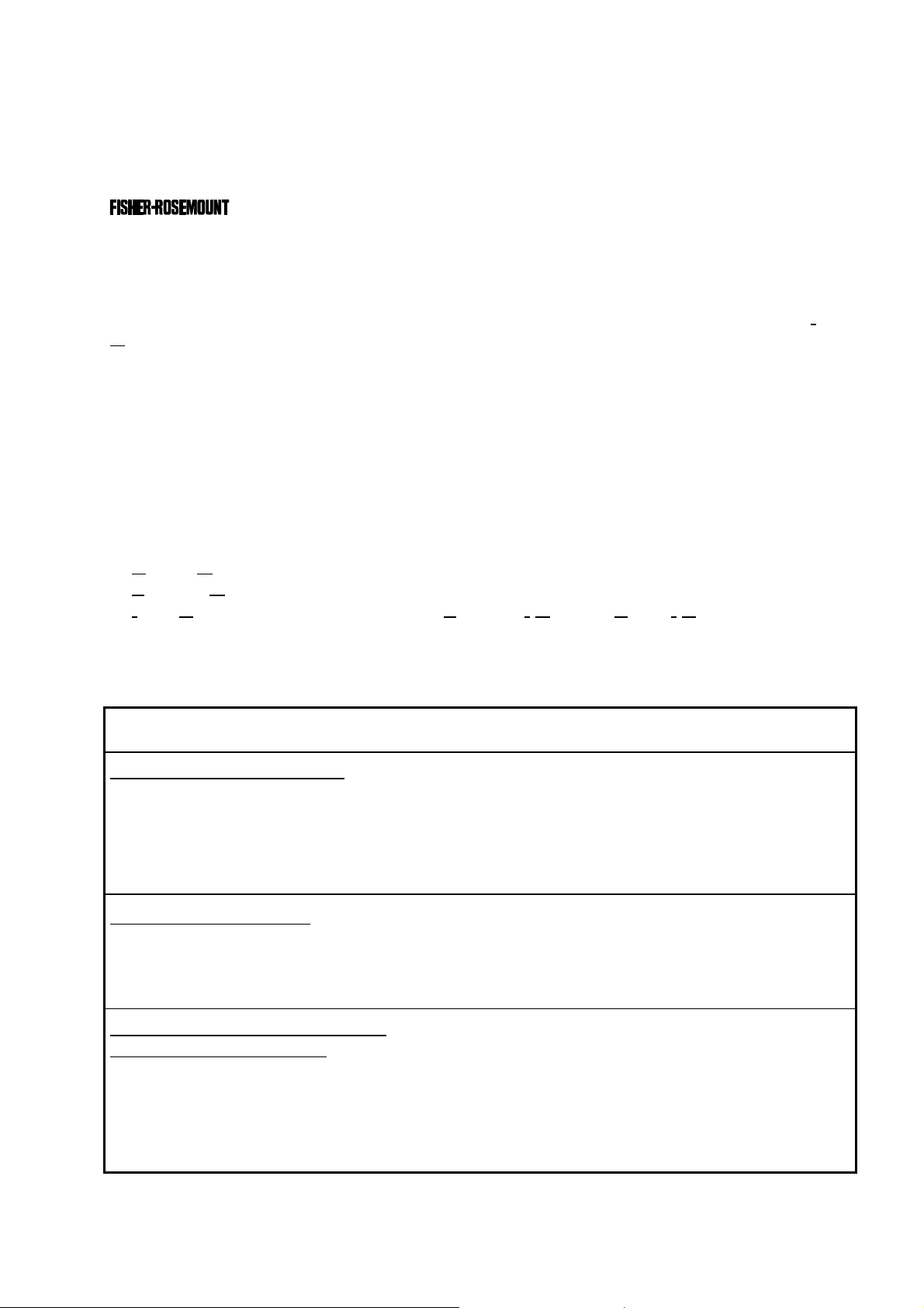
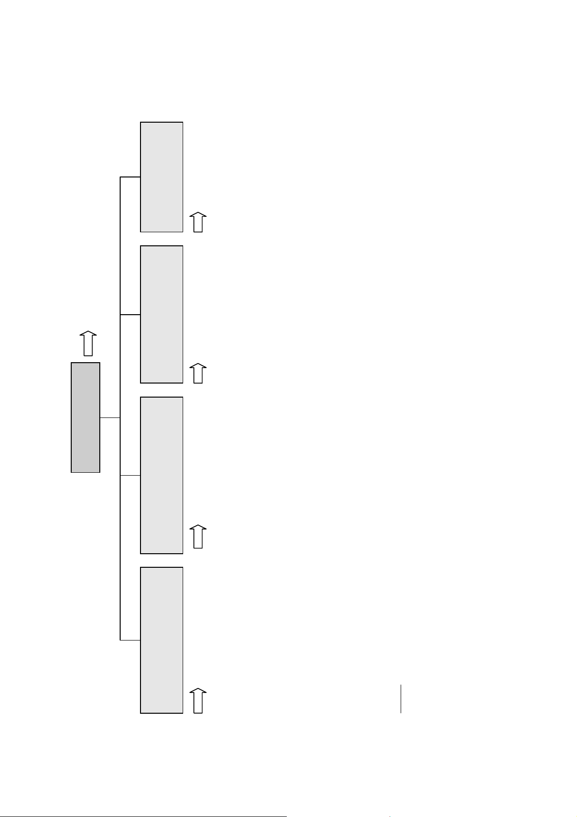
The following illustrations explain the relationship between the hardware configuration and
A
the software setup of the modules:
NGA 2000 System containing a Platform
(see 5.1.18)
(see 5.1.18)
Local
I/O's
SIO
nalyzer
Modules (AM's)
Control
Module (CM)
System I/O
TFID
DIO
SIO
MLT
DIO
(additional
manuals)
(additional
manuals)
(additional
manuals)
CLD
Platform
PMD
FID
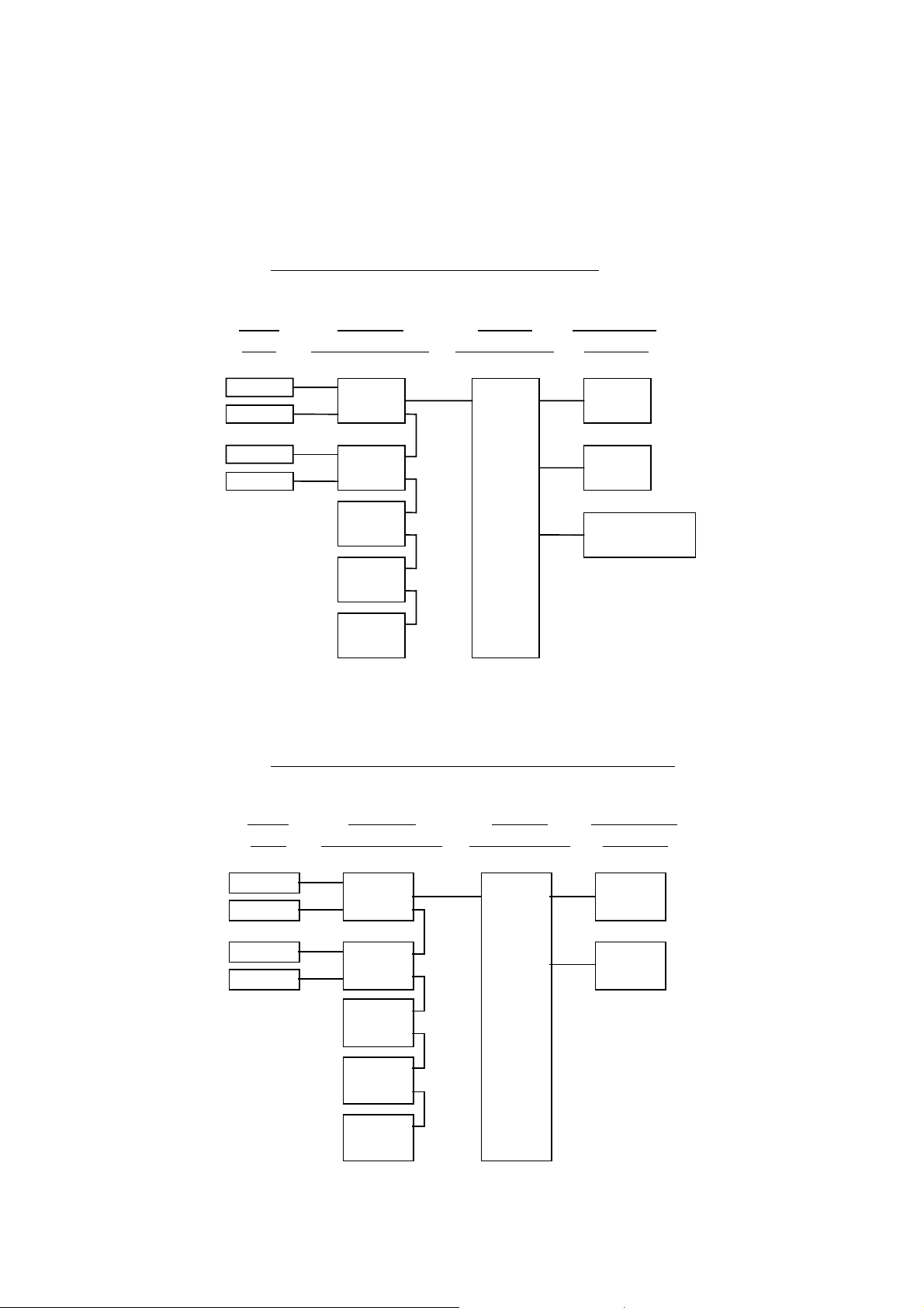
NG A 2000 Sy stem containing an TFID Analyzer
Modules
1 SIO
4 DIO's
max.
Network I/O
(see 5.2.1)
(see 5.2.2)
(see 5.1.18)
(see 5.1.18)
Local
I/O's
SI O
DIO
SI O
DIO
(additional
manuals)
(additional
manuals)
(additional
manuals)
Analyzer
Modules (AM's)
TFID
MLT
CLD
PMD
FID
Control
Module (CM)
System I/O
Modules
1 SIO
(see 5.2.1)
1 DIO
(see 5.2.2)
TFID Analyzer
1 - 2
NGA 2000
ETC00612(1) [NGA-e (TFID SW 3.4.X)] 02/01
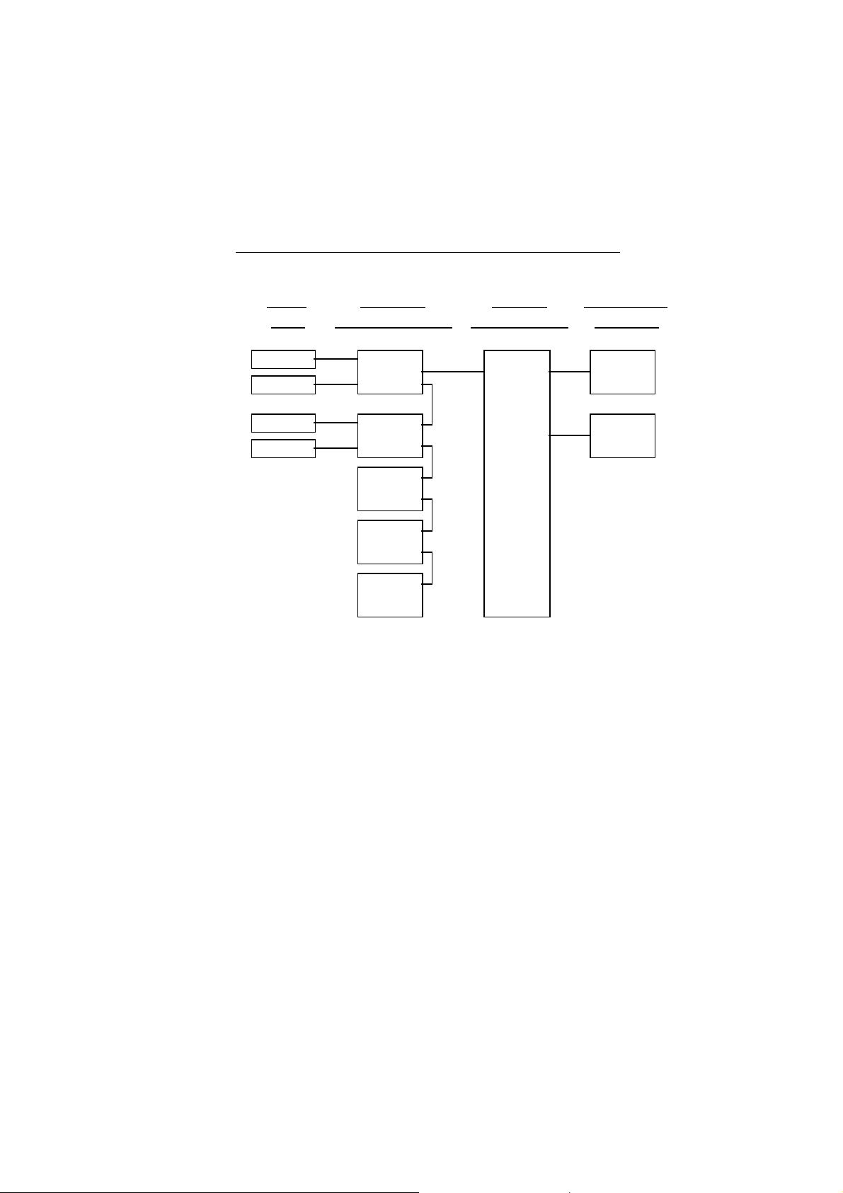
1 Introduction
NGA 20 0 0 Sys te m co nt aining an ML T Ana ly zer
Local
I/O's
(see 5.1.18)
(see 5.1.18)
SIO
DIO
SIO
DIO
(additi onal
manuals)
(additi onal
manuals)
(additi onal
manuals)
Note:
This software manual describes the software of all TFID analyzers and TFID analyzer
modules combined with a platform, an FTID analyzer or an MLT analyzer.
It will not describe the software of TFID analyzer modules running at a customer control
unit.
The software of MLT analyzers / MLT analyzer modules is nearly identically to the TFID
software. An separate software manual is available containing the MLT specific functions.
Analyzer
Mod u le s (AM's)
MLT
TFID
CLD
PMD
FID
Control
Mod u le (CM)
MLT Analyzer
System I/O
Modules
1 SIO
1 DIO
( see 5. 2 .1)
( see 5. 2 .2)
ETC00612(1) [NGA-e (TFID SW 3.4.X)] 02/01
NGA 2000
1 - 3

1 - 4
NGA 2000
ETC00612(1) [NGA-e (TFID SW 3.4.X)] 02/01
2 Menu Structure
Section 3.8
System configuration
Main Menu
Analyzer and I/O, expert
Display controls...
- Brightness:
- Contrast:
(CM)
to "Measure" after
- Switch automatically
...
and diagnostics...
(AM, CM, network I/O's)
- System calibration...
- Diagnostic menus...
local SIO/DIO)
incl.
(CM/MCA)
- Load/save configuration
controls & setup...
(AM
- Analyzer module controls...
(System I/O's: SIO, DIO)
module controls...
- System & network I/O
(CM)
(Lock any level)
- Security codes (PIN)...
- Date and time...
like
controls)
MLT/TFID
for
analyzer module
(AM:
- Analyzer module setup...
(CM)
(CM)
(AM, CM, I/O's: SIO, DIO etc.)
- Network module managment...
- System reset...
- System tag:
(Network I/O's)
module setup...
- System & network I/O
(calibration) & setup...
Analyzer basic controls
ETC00612(1) [NGA-e (TFID SW 3.4.X)] 02/01
Section 4 Section 5 Section 6 Section 7
- Flow zero gas!
- Calibration procedure state...
- Start zero calibration procedure!
- Start span calibration procedure!
- Check calibration deviation:
- Range number:
- Span gas:
- Range upper limit:
NGA 2000
- Flow span gas!
- Valves => F5:
- Flow sample gas!
- Flow test gas!
- Close all valves!
Notes:
the function, lines ending with ":" display module parameters - some can be changed.
* All setups in the menu "Analyzer basic controls (calibration) & setup" are valid for the analyzer or analyzer module (AM).
* Menu lines ending with three points (...) are followed by submenus with further functions and setups, lines ending with "!" allow to start
you can find which functionality will be setup:
AM (A nalyzer Module), CM (C ontrol Module), local, system or network I/O (Input/Output Module).
* At each menu point of the "Analyzer and I/O, expert controls & setup" and "System configuration and diagnostics"
2 - 1

2 - 2
NGA 2000
ETC00612(1) [NGA-e (TFID SW 3.4.X)] 02/01
3
A
Startup and Operation, General Notes and Main Menu
3.1 Starting and Initializing (Refer to the operation manual, too !)
After switching on the TFID analyzer / analyzer module ( as part of a NGA network), the
initialization procedure will be performed. . A self test is started showing a sequence of
several screens with information about the initialization status, software revision notes and
the
tag:
(C) 2000 FISHER-ROSEMOUNT Analytical
NGA-2000 Control-Module Rev. 3.4 /P010
LCDReset
F1 F2 F3 F4 F5
Language:P010/01/00
Initializing Network
Initializing network interface
bort
The network is initialized while the screen shows the messages “Initializing network
interface” , “ Searching for nodes” and “Calculating binds”.
If you press the F1-key during the initializing, you will reset the LCD brightness and
contrast to factory settings (see also section 7). Pressing the F3-key will abort the
network initializing. There will be no connection to any analyzer module. Only the control
module menus (platform or TFID analyzer) will be available.
At the end of the initializing procedure you can see the single component display of
channel one (see illustration on next page). It is the starting point to all the other channel
displays, menus and submenus.
The instructions of the basic controls (chapter four) are all beginning at the single component display. Since this screen is customer configurable the actual analyzer display
might differ from the one shown in this manual (see section 5.1.8 pg. 5-49 and section 7).
ETC00612(1) [NGA-e (TFID Software 3.4.X)] 06/01
NGA 2000
3 - 1

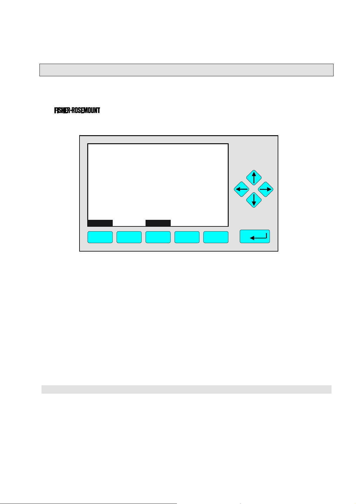
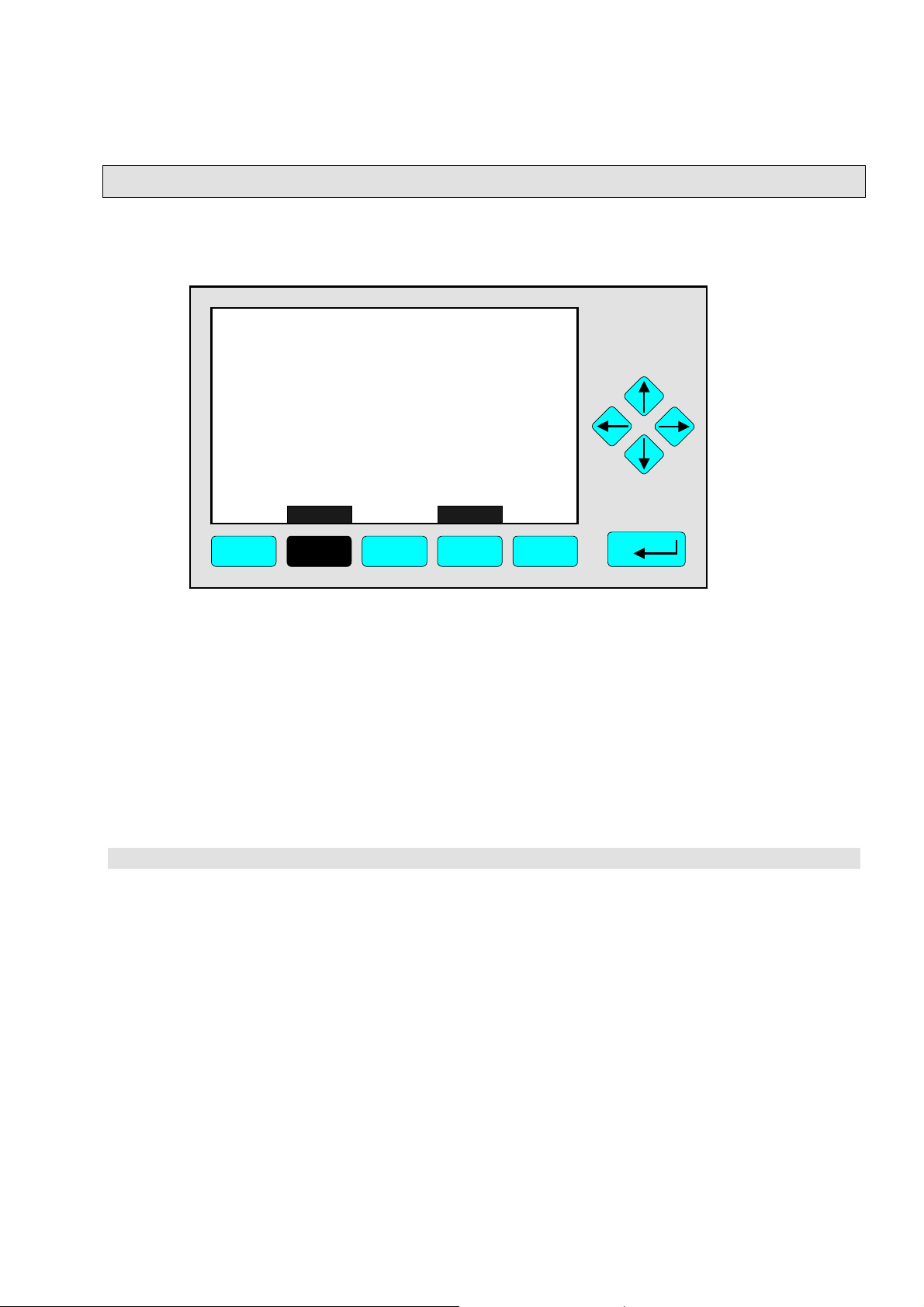
3.2 Display and Function
The LCD screen shows all analyzer measurement values and all customer instructions.
You can operate with five function keys, four arrow keys (cursors) and the enter key. The
function of each key depends on:
♦
the type of analyzer/analyzer module used
♦
the optional auxiliary modules (e.g. I/O boards) used
♦
the individual menu displayed
In case of power failure all customer specific module parameters are saved in a battery-
powered buffer.
3.3 "TAG" and Operating Keys
At the top left of each menu page you will find the tag of the current channel.
Typical tags:
♦ TFID/R1: T
♦
MLT/CH1/R1: MLT Analyzer or Analyzer Module / CHannel 1 / Range 1
By default screen dumps in this manual will show "TAG". Specific TFID menu pages will use
"TFID" instead to show this property.
hermo FID Analyzer or Analyzer Module / Range 1
TAG
37.50 ppm CH4
0.00 50.00
Failures: No
Maintenance-Requests: No
Temperature: 20.0 C
Operation: Ready
Display Status... Main... Channel
F1 F2 F3 F4 F5
Range: 1
0.0 100.0
BasicCal
Function Keys:
♦
Keys without defined function
♦
The current function depends on
the menu selected
♦
The softkey legend is shown on
the display right above the key
Cursor keys:
↑↑↑↑ -key / ↓↓↓↓ -key:
♦
Line up / line down
within the same menu
♦
Alteration of numbers,
variables or digits
←←←← -key / →→→→ -key:
♦
Moving back/forth
between the pages of
a menu
♦
Selection of digits
♦
Start a selected
function
Enter Key:
♦
To confirm a previously entered value
(variable)
♦
To start a selected function
(alternative
♦
To enter a menu (via menu line)
: →→→→ -key)
3 - 2
NGA 2000
ETC00612(1) [NGA-e (TFID Software 3.4.X)] 06/01
3
p
w
Startup and Operation, General Notes and Main Menu
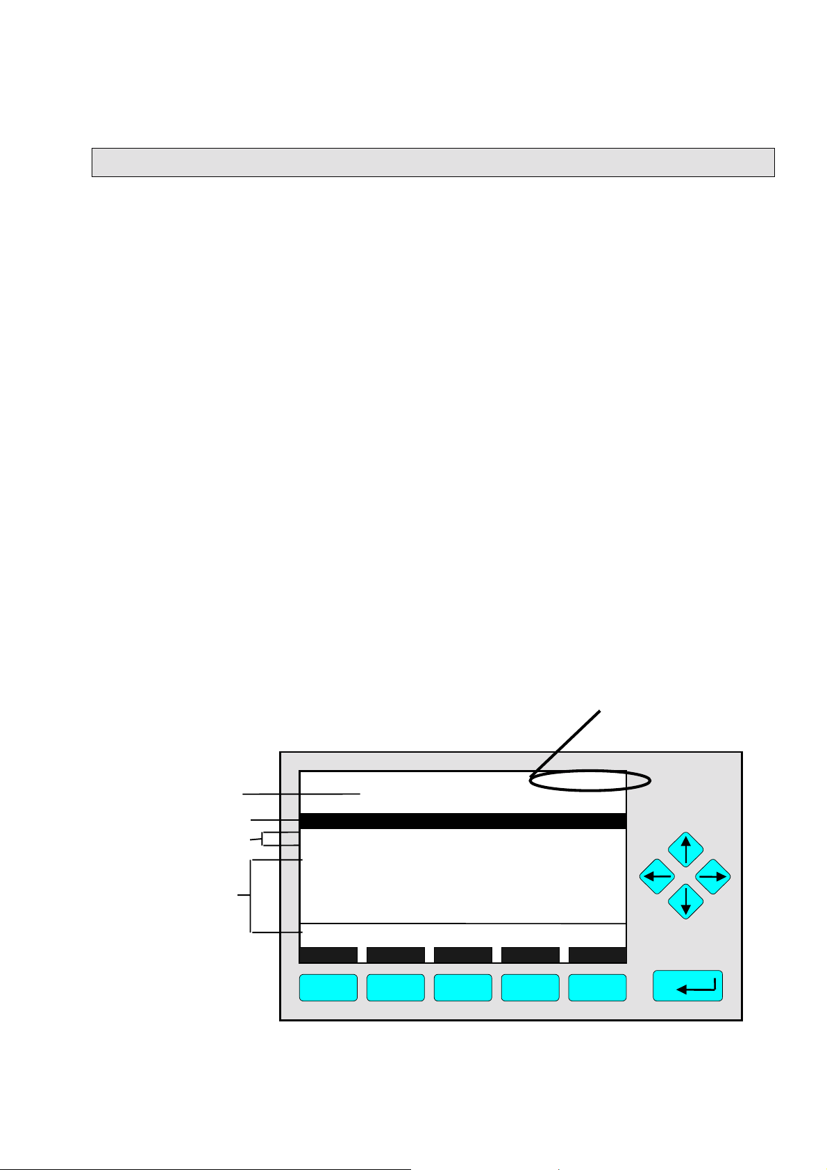
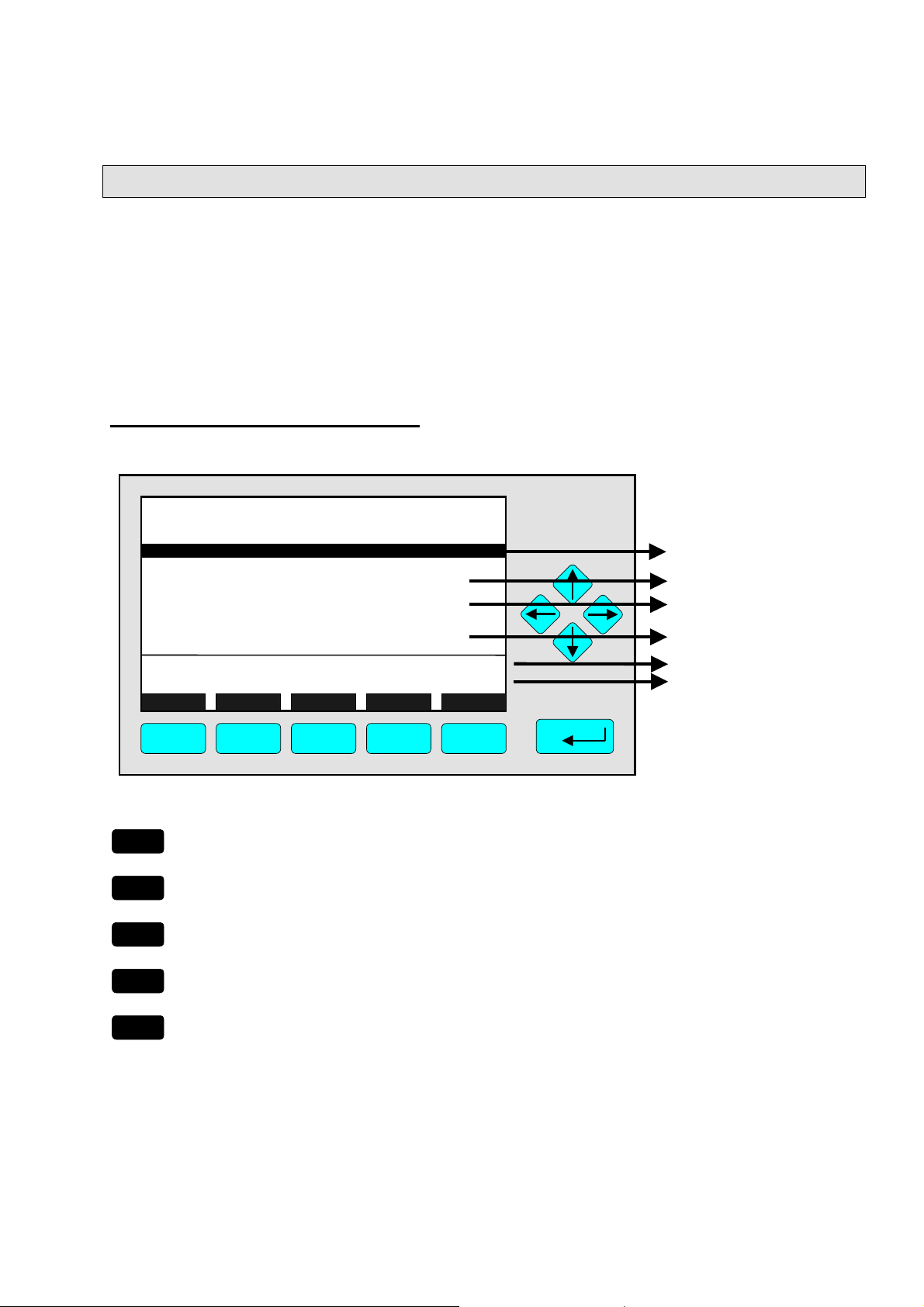
3.4 Lines and Softkey Functionality
Lines can be selected by using the ↓↓↓↓ -key or the ↑↑↑↑ -key. The selected line is displayed
white on black (highlighted). There are four different types of lines in the menus:
Menu line... / Menu Softkey...
♦
Line/Softkey description ending with three dots.
♦
You will enter a submenu/next menu by pressing the softkey resp. by pressing the
↵↵↵↵
-key or the →→→→ -key while the menu line is highlighted.
Function line / Function Softkey !
♦
Line/Softkey description ending with an exclamation-mark.
♦
You will start a function (e.g. calibration) by pressing the softkey resp. by pressing the
↵↵↵↵
-key or the →→→→ -key while function line is highlighted.
Line of variables:
♦
Line ending with a colon.
♦
View module parameters (variables).
♦
Some parameters can be changed (e.g. begin of range). Other parameters showing a
status (e.g. temperature) are for information only and cannot be changed. They are
displayed below a separation line within the menu.
Text line
♦
Line without any punctuation marks.
♦
Giving additional information only (such as headlines a.s.o.).
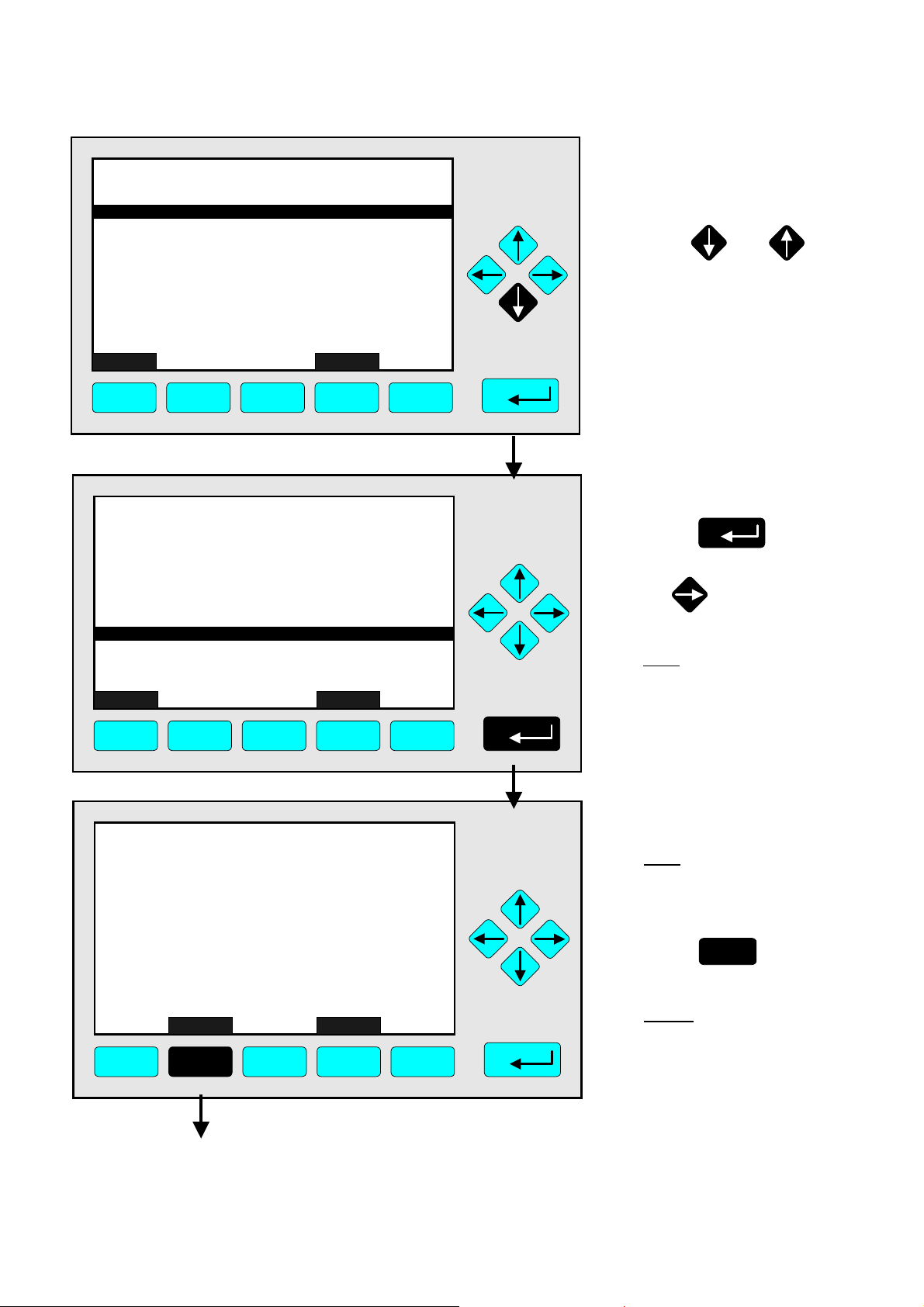
The following illustrations explain the function of lines and softkeys as described above:
Current channel measurement signal (see TAG).
It is always shown on the single component display.
Menu Headline
Menu Line
Function Lines
Lines of Variables
(The last one can not
be changed – belo
the separation line)
TAG
-- Basic Controls and Setup --
Calibration procedure status...
Start zero calibration procedure!
Start s
Check calibration deviation:
Range number:
Span gas: 100 ppm
Range upper limit: 100 ppm
Operation status: Ready
an calibration procedure!
Measure Status... Channel Back...
37.50 ppm
Enabled
1
Valves...
F1 F2 F3 F4 F5
ETC00612(1) [NGA-e (TFID Software 3.4.X)] 06/01
NGA 2000
3 - 3
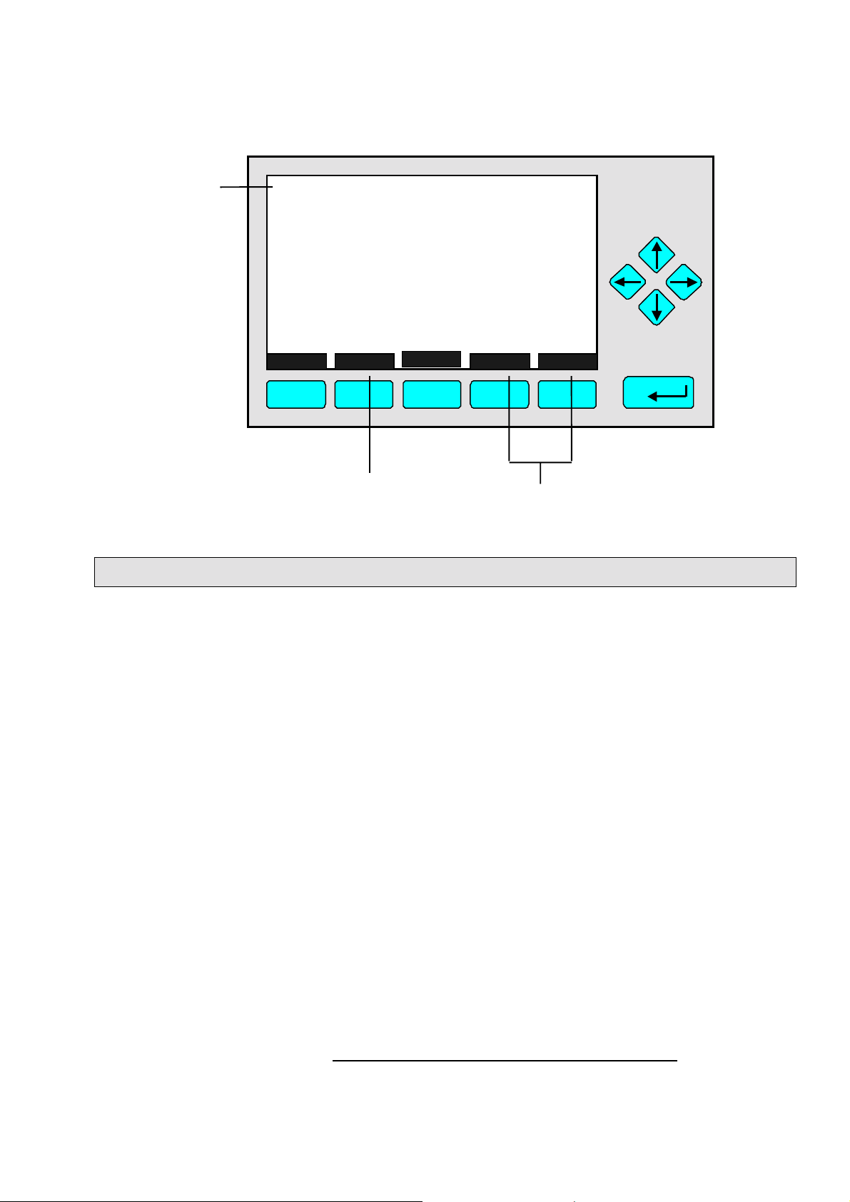
TAG
Text Line
-- Calibr ation Pr oc edure State --
Proc edure state:
Maximum rema in ing procedure time :
Valve position:
Concent ration in span gas units:
Last zero calibration:
Last span calibrati on:
Last zero calibration was:
Last spa n cal ibra t ion was:
Succ essful zero+span ca libr ated ranges:
Measure Cancel !
F1 F2 F3 F4 F5
Function Softkey
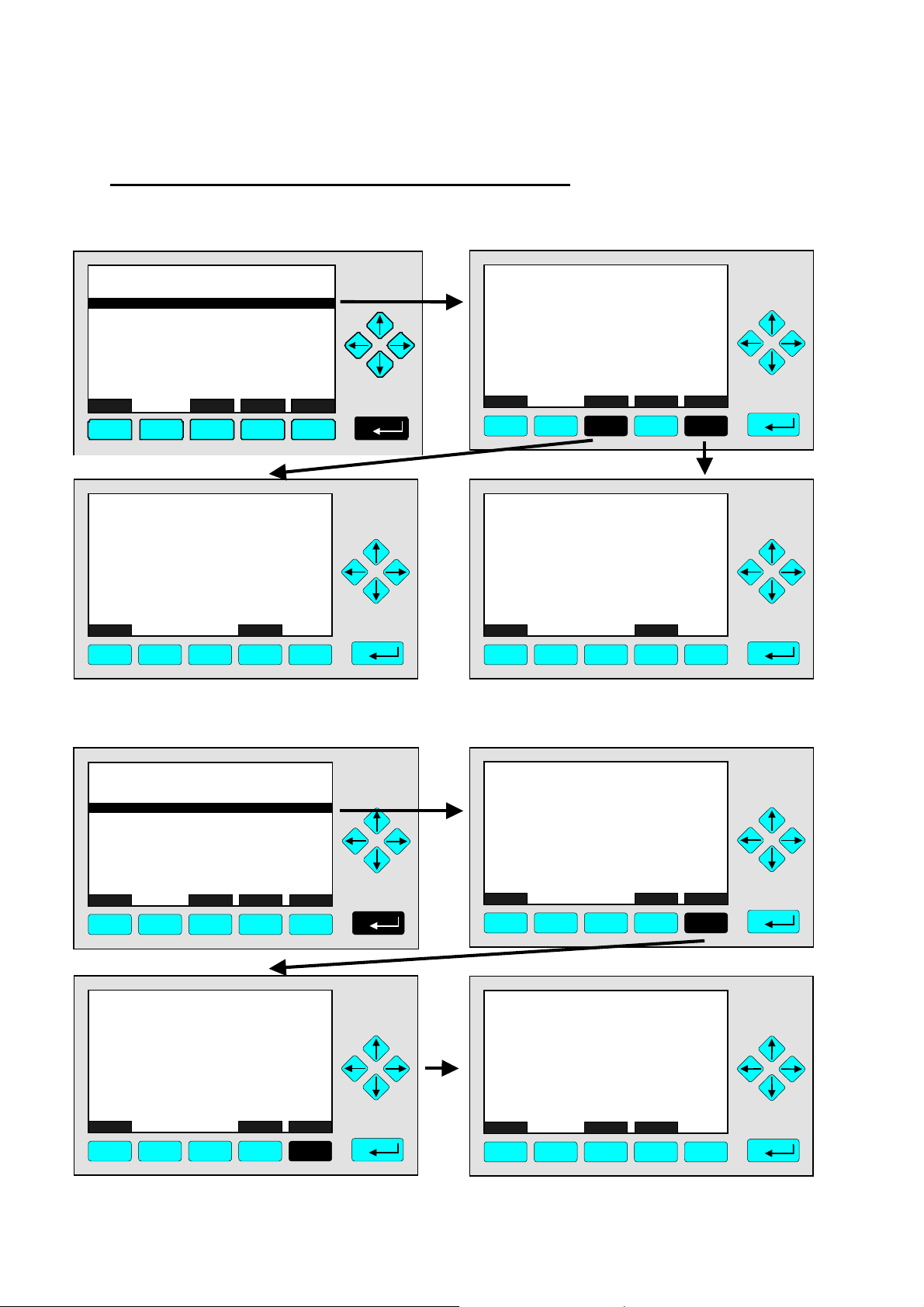
3.5 Important Function Softkeys
Channel
37.50 ppm
Ready
Samplegas
37.50 ppm
Success
Success
1+2+3+4
More...
Fr i 05-29-1998 13:32:0 6
Fr i 05-29-1998 13:37:2 3
Back...
Menu Softkeys
0 s
Display
♦
Switch from the single component display to the multi component display.
♦
F1 in the single component display.
Measure
♦
Switch from any menu or submenu to the single component display of the selected
channel.
♦
F1 in any screen except the single component display.
Status (see section 4.1 page 4-3!)
♦
Switch to the menu "Analyzer Channel Status":
Shows the most important parameters and information about the status of the current
channel or module.
♦
If available: F2.
Main (see section 3.8 page 3-7!)
♦
Switch from the single component display to the main menu.
♦
F3 in the single component display.
Channel
♦
Scroll through the channels in the current menu. In the main menu and the single
component display you may scroll through all channels of the connected analyzer /
analyzer modules. In submenus this key is without function although it is displayed (only
activated in MLT software). TFID is a single channel analyzer or AM only!
♦
If available: F3 (F4 in the single component display).
3 - 4
NGA 2000
ETC00612(1) [NGA-e (TFID Software 3.4.X)] 06/01

3
Startup and Operation, General Notes and Main Menu
Lock
♦
Lock all three operation levels at the main menu if a security code is activated in the
system configuration and diagnostic menu (see section 6.4 pg. 6-8).
♦
F4 in the main menu.
BasicCal (see section 4.4 pg. 4-19 and 5.1.1 pg. 5-15!)
♦
Switch from the single component display to the menu "Analyzer module calibration".
♦
F5 in the single component display.
MFG Data (see section 3.8 pg. 3-7/8!)
♦
Switch from the main menu to the menu "Module Manufacturing Data":
Additional submenus are available with information about the control module and
analyzer module data, such as manufacturer address , modules serial numbers or
software and hardware revisions.
♦
F5 in the main menu.
Back
♦
Return to the previous menu page (alternative: ←←←← -key)
♦
reset a changed but not confirmed parameter to the previous value.
♦
If available: F4 for returning back, F2 for reset.
More
♦
Entering the next page of the current menu.
♦
If available: F5.
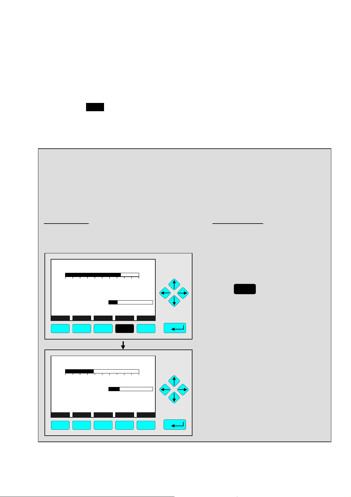
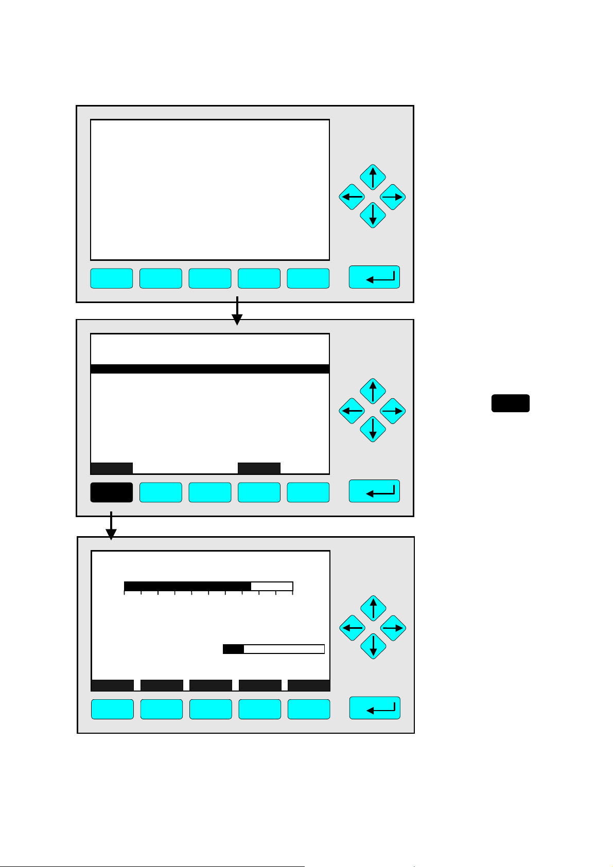
3.6 Entering/Changing Variables
↵↵↵↵
-key
♦
If you have already selected a line of variables (highlighted) and press the
↵↵↵↵
-key, the
parameter will be selected and may be edited.
↵↵↵↵
If you press the
-key again, the new value will be confirmed.
↑↑↑↑ -key / ↓↓↓↓ -key
♦
Function depends on the variable selected: - Changing the parameter values
- Scrolling among variables selecte d
- Changing single digits or characters
- Increasing or decreasing numbers.
←←←← -key / →→→→ -key
♦
Selects single digits within a number.
♦
The number of digits or characters of some variables may be changed.
ETC00612(1) [NGA-e (TFID Software 3.4.X)] 06/01
NGA 2000
3 - 5
3.7 Executing a Function
If you press the
↵↵↵↵
-key or the →→→→ - key while a functio n line is highligh ted the software will
ask for a confirmation:
TAG
-- Confirmation Required --
Do you really want to do this ??
Press "Yes" or "Back..."
Yes Back...
F1 F2 F3 F4 F5
37.50 ppm
♦
If you press the F2 -key the function will start imm e diately.
♦
Pressing the F4 -key will return to the previous menu page.
Note:
Confirmation of function line entries may be disabled:
♦
Select “Measurement Display Configuration” from the Analyzer and I/O, expert controls
& setup menu (see section 5.1.8, page 5-49).
♦
Change “Display confirmation menus” to “No”.
Now the selected function will start immediately after entering. No confirmation is
required.
3 - 6
NGA 2000
ETC00612(1) [NGA-e (TFID Software 3.4.X)] 06/01
3
Startup and Operation, General Notes and Main Menu
3.8 Main Menu
If you press the F3-key (Main...) or the →→→→-key in any single component display, you will
switch to the "Main Menu". From there you can switch to all operating levels of your
TFID/MLT analyzer / analyzer module to set up and control the parameters of
measurement, calibration and data transfer!
Via the F5-key (MFG Data) you may enter several submenus where you will find a lot of
important data about the control module (TFID/MLT analyzer / platform) and the analyzer
module, such as service address or serial number!
Ramifications from the Main Menu:
TAG
-- Main Menu --
Analyzer basic controls (calibration) & setup...
Analyzer and I/O, expert controls & setup...
System configuration and diagnostics...
Display controls...
Time & Date: 14:01:45 25 May 1999
System tag: Fisher-Rosemount
Measure Status... Channel Lock... MFG Data
F1 F2 F3 F4 F5
F1
F2
F3
Enter the current channel’s single component
display
Enter the current channel’s "Analyzer Channel
Status" menu.
Scroll through all channels of connected
analyzers / analyzer modules
95.00 ppm
☞
☞
☞
See chapter 4 !
See chapter 5 !
See chapter 6 !
See chapter 7 !
Setup: see 6.3 pg. 6-7
Factory setting
Section 3.1, pg. 3-1/2 !
Section 4.1, pg. 4-3 !
See channel tag !
F4
F5
Lock any operating level by security code
Enter the menu "Manufacturing Data"
ETC00612(1) [NGA-e (TFID Software 3.4.X)] 06/01
NGA 2000
☞
☞
Section 6.4, pg. 6-8 !
See next pages !
3 - 7
Ramifications from the menu "Manufacturing Data":
1. Control module data:
TAG
-- Manufacturing Da ta --
Control modul e manufac turing data...
Analyzer module manufacturing data.. .
Meas u re
F1
F2
<<<
F3
F4
Back...
95.00 ppm
TAG
(C) Copyright Fisher-Rosemount Analytical Inc., 2001
Manufactured by:
Rosemount Analytical Inc.
4125 East La Palma Avenue
Anaheim, CA 92807-1802 /USA
Tel: (714) 986-7600
FAX: (714) 577-8739
Measure Back...
F1 F2 F3 F4 F5
95.00 ppm
2. Analyzer module data:
>>>
F5
TAG
(C) Copyright Fisher-Rosemount GmbH & Co, 2001
Manufactured by:
Fisher-Rosemount GmbH & Co
Industriestrasse 1
D-63594 Hasselroth / Germany
Tel. (+49) 6055 884-0
FAX. (+49) 6055 884-209
Measure Or... Back... More...
F1 F2 F4 F5
F3
95.00 ppm
TAG
-- Control Module Version Information --
Serial number: CM 4711
Manufacturing date: 14.02.2001
Hardware revision: ACU02 R: 3.2.4, Final D:Jan 1
Software revision: 3.4/P010
Revision date: Nov 2 2000
Revision time: 16:09:49
Phrase dictionary version:
Language: English
Measure Back...
F1 F2 F3 F4 F5
95.00 ppm
P010/01/00
TAG
Control module data...
Analyzer module data...
Measure
F1 F2 F3 F4 F5
-- Module Manufacturing Data --
<<<
Back...
95.00 ppm
>>>
TAG
-- Analyzer Module Version Information --
Serial number: AM 4712
Manufacturing date: 14.02.2001
Hardware revision: ACU02 R: 3.2.4, Final D:Jan 1
Software revision: 3.4.1 / P010/Ch1
Revision date: Nov 2 2000
Revision time: 16:25:28
Measure Back...
F1 F2 F3 F4 F5
95.00 ppm
More...
TAG
(C) Copyright Fisher-Rosemount GmbH & Co, 2001
Manufactured by:
Fisher-Rosemount GmbH & Co
Industriestrasse 1
D-63594 Hasselroth / Germany
Tel. (+49) 6055 884-0
FAX. (+49) 6055 884-209
Measure Back... More...
F1 F2 F3 F4 F5
TAG
Measurement system: PSV-System
RAM-memory: 763296 Bytes
Local SIO module installed: Enabled
Serial interface adapter: RS-232
Heater installed: No
Local DIO module installed: 2
Sensor system revision:
Sensor system serial number:
Measure Back...
F1 F2 F3 F4 F5
-- Hardware Configuration --
Channel
95.00 ppm
95.00 ppm
04011999
311976
3 - 8
NGA 2000
ETC00612(1) [NGA-e (TFID Software 3.4.X)] 06/01
4 Analyzer Basic Controls (
Calibration) & Setup
Chapter 4 "Analyzer basic controls (calibration) & setup" describes the most important
measurement and calibration functions of your TFID/MLT analyzer / analyzer module.
All steps are figured with detailed illustrations and operation instructio ns. In the left column
you can see display and keyboard of the NGA front panel. The keys you have to press are
illustrated in black. In the right column you can read the instructions and notes. All
instructions will begin with any single component display and will end with the corresponding single component display after the setups are done. So you can easily compare the
actual display of the analyzer / analyzer module with the illustrations of this manual.
Example:
You want to change from the single component display of the TFID (propane) to the single
component display of the MLT channel 2 (CO).
• Picture one shows the starting situation: single component display of propane.
• Picture two shows the result you get if you press the F4 -key (Channel):
single component display of CO.
Left column: Right column:
Display and keyboard Instructions and notes
TFID-R1
37.50 ppm Propane
0.00 50.00
Failures: No
Maintenance- No
Temperature: 20.0 C
Operation: Ready
Display Status... Main... Channel BasisCal
F1 F2 F3 F4 F5
MLT25/CH2/R2
95.00 ppm CO
0 250Range: 2
Temperature: 25.0 C
MaintenanceAny_Alarms: No
Operation: Ready
Display Status... Main... Channel BasisCal
F1 F2 F3 F4 F5
Range: 1
0.0 100.0
0.0 100.0
No
⇒ Switch to the single
component display
of another channel
F4
Press
Notice the tag in the
display's upper left corner:
It changed fro m TFID to
MLT2 indicating a different
analyzer / analyzer module.
⇒ Next instruction
or step may be
entered.
ETC00612(1) [NGA-e (TFID SW 3.4.X)] 02/01
NGA 2000
4 - 1

4 - 2
NGA 2000
ETC00612(1) [NGA-e (TFID SW 3.4.X)] 02/01
TAG
37.50 ppm CH4
0.00 50.00
Failures: No
Maintenance-Requests: No
Temperat ure: 20.0 C
Operation: Ready
Display Status... Main... Channel BasicCal
F1 F2 F3 F4 F5
Range: 1
0.0 100.0
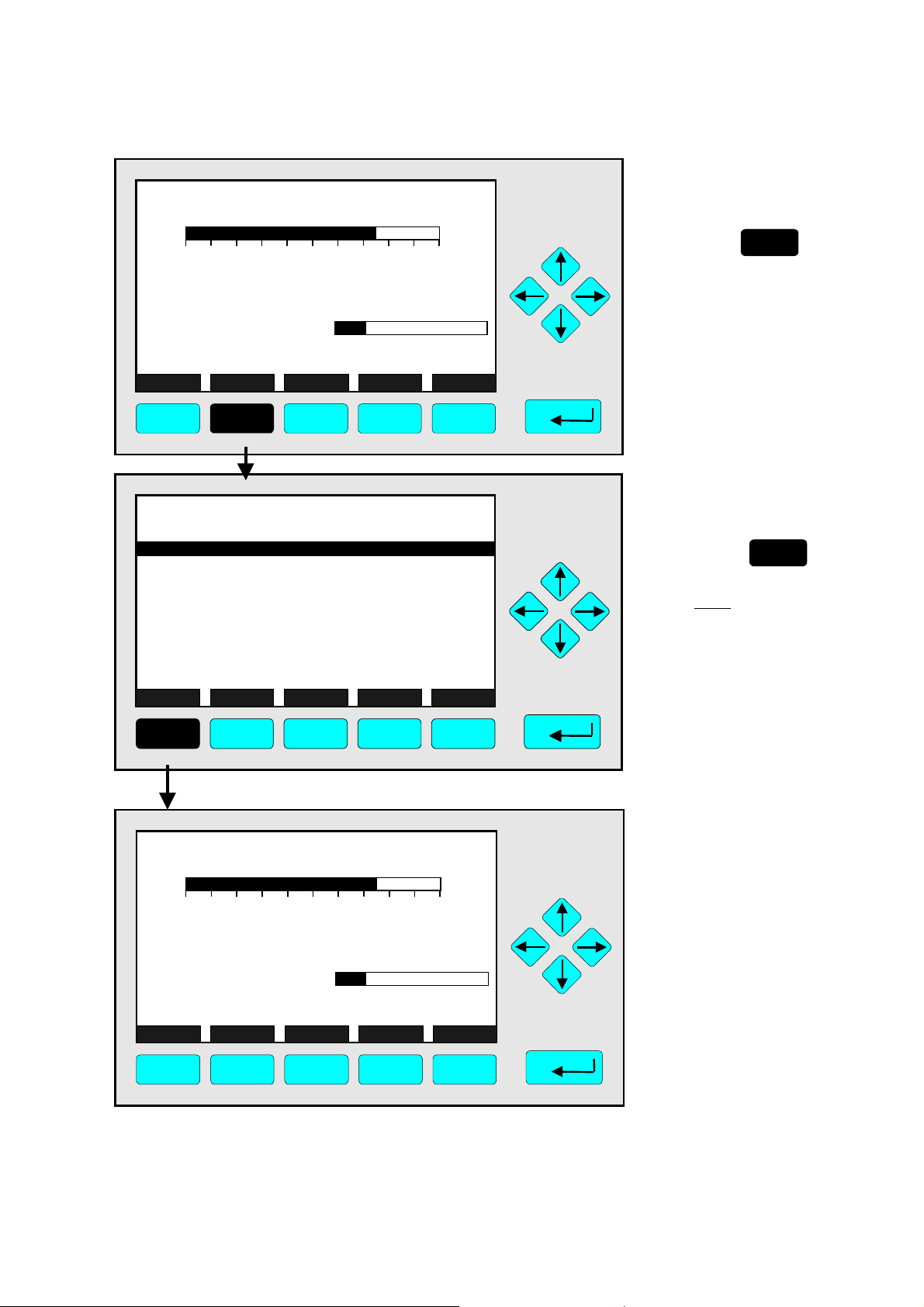
4.1 Analyzer Channel Status
⇒ Open the menu
"Analyzer Channel
Status"
F2
Press
The menu "Analyzer
Channel Status” displays
status information about
the current channel.
Use the menu lines
"Status details..." and
"Current operation
parameters..." to enter
submenus.
(see 4.1.1 pg. 4-5...11 and
4.1.2 pg. 4-13/14)
TAG
-- Analyzer Channel Status --
Status details...
Analyzer operation settings...
General status: Normal
Hours of operation: 164
Operation status: Ready
Events: No
Alarms: No
Failures: No
Maintenance requests: No
Function control/Service: No
Measure Channel Back...
RawMeas More...
37.50 ppm
F1 F2 F3 F4 F5
TAG
37.50 ppm CH4
0.00 50.00
Failures: No
Maintenance-Requests: No
Temperat ure: 20.0 C
Operation: Ready
Range: 1
0.0 100.0
⇒ Return to the single
component display
F1
Press
Note:
The F2 -key enters the
•
submenu “Primary raw
measurements” and
from there in a second
step using F5 to
”Secondary raw
measurements”.
Via the F5 -key you can
•
switch to submenu "TFID
Pressure & Temperature
Measurements".
⇒ Back in the single
component display
Display Status... Main... Channel BasicCal
F1 F2 F3 F4 F5
ETC00612(1) [NGA-e (TFID SW 3.4.X)] 02/01
NGA 2000
4 - 3

4 - 4
NGA 2000
ETC00612(1) [NGA-e (TFID SW 3.4.X)] 02/01
4.1.1 Analyzer Channel Status -
TAG
37.50 ppm C H 4
0.00 50.00
Failures: No
Maintenance-Requests: No
Temperature: 20.0 C
Operation: Ready
Display Status... Main... Channel BasicCal
F1 F2 F3 F4 F5
TAG
-- Analyzer Channel Status --
Status details...
Analyzer operation settings...
General status: Normal
Hours of operation: 164
Operation status: Ready
Events: No
Alarms: No
Failures: No
Maintenance requests: No
Function control/Service: No
Measure Channel Back...
RawMeas More...
F1 F2 F3 F4 F5
Range: 1
0.0 100.0
37.50 ppm
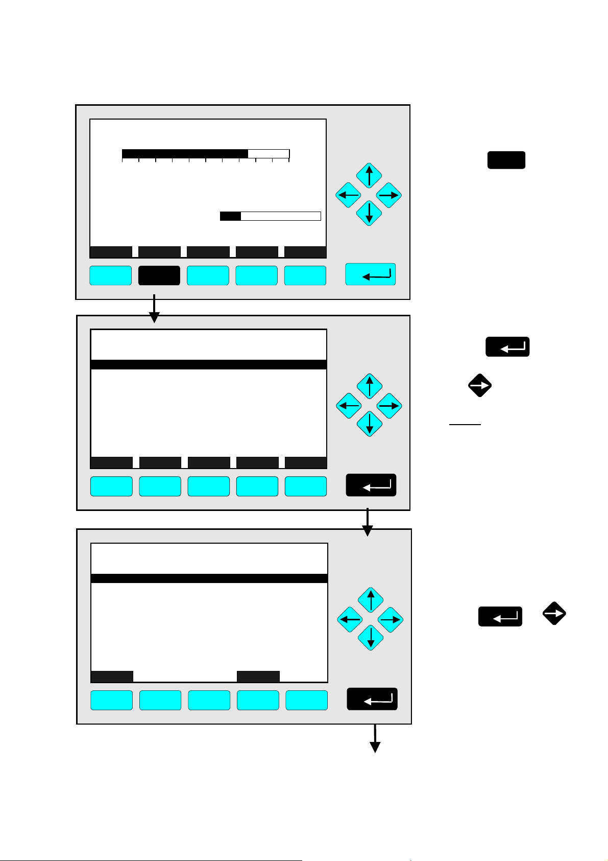
Status Details
e.g. Failures
⇒ Open the menu
"Analyzer Channel
Status"
F2
Press
⇒ Enter the submenu
"Status Details"
Press
or
Note:
Use the way described
below to enter other submenus of status details:
Maintenance requests
•
Function controls
•
Alarms
•
Events
•
TAG
-- Status Details --
Failures...
Maintenance requests...
Function controls...
Alarms...
Events...
Acknowledge and clear failures !
Acknowledge and clear maintenance requests !
Acknowledge and clear function controls !
Measure Back...
F1 F2 F3 F4 F5
ETC00612(1) [NGA-e (TFID SW 3.4.X)] 02/01
37.50 ppm
NGA 2000
⇒ Enter the menu "List of
Possible Failures (1/4)"
↵↵↵↵ -
or
key
4 - 5
Press
Note:
If you want to see other
available status details,
highlight the line you want
using the ↓↓↓↓- or ↑↑↑↑- key and enter
pressing the

TAG
-- List of Possible Failures (1/4) --
One or more f ai lures:
Hydrogen pre s sure too low:
No sourc e voltage:
Invalid inter ference compensat ion:
Sample gas pump #1 fail:
Sample gas pump #2 fail:
Detec tor temper ature too low:
Flame i s off:
Ignition cance le d:
Measure
Back...
37.50 ppm
More...
No
No
No
No
No
No
No
No
No
⇒ Enter the second
menu page
Press
F5
F1
TAG
External Input: No
Probe temperature too low: No
Probe temperature too high: No
Flame temperature sensor fail: No
Sample under pressure too high: N o
Capillary #1: No
Control of sample gas pump #1 fail: No
Sample gas pressure too high: No
Control of sample gas pump #2 fail: No
Measure Back... More...
F1 F2 F3 F4 F5
TAG
Sample gas (Filter/supply/under pressure): No
Capillary #3 or H2 supply: No
Detector signal communication failed: No
Power supply less than 23V: No
Air pressure less than 2.9 bar: No
Igniter broken: N o
Igniter short-circuit: No
Detector temperature sensor fail: No
Sensor temperature sensor fail: No
Ambient temperature too high: No
Measure Back... More...
F2
-- List of Possible Failures (2/4) --
-- List of Possible Failures (3/4) --
F3
F4
37.50 ppm
37.50 ppm
F5
⇒ Enter the
third menu page
F5
Press
⇒ Enter the
last menu page
F5
Press
F1 F2 F3 F4 F5
4 - 6
NGA 2000
ETC00612(1) [NGA-e (TFID SW 3.4.X)] 02/01
4.1.1 Analyzer Channel Status -
TAG
-- List of Possible Failures (4/4) --
Sample gas throttle closed: No
Burner gas throttle closed: No
Under pressure pump fail: No
Sample gas pump fail: No
Burner gas pump fail: No
Sample gas control valve fail: No
Burner gas control valve fail: No
Measure Back... (1/4)...
F1 F2 F3 F4 F5
37.50 ppm
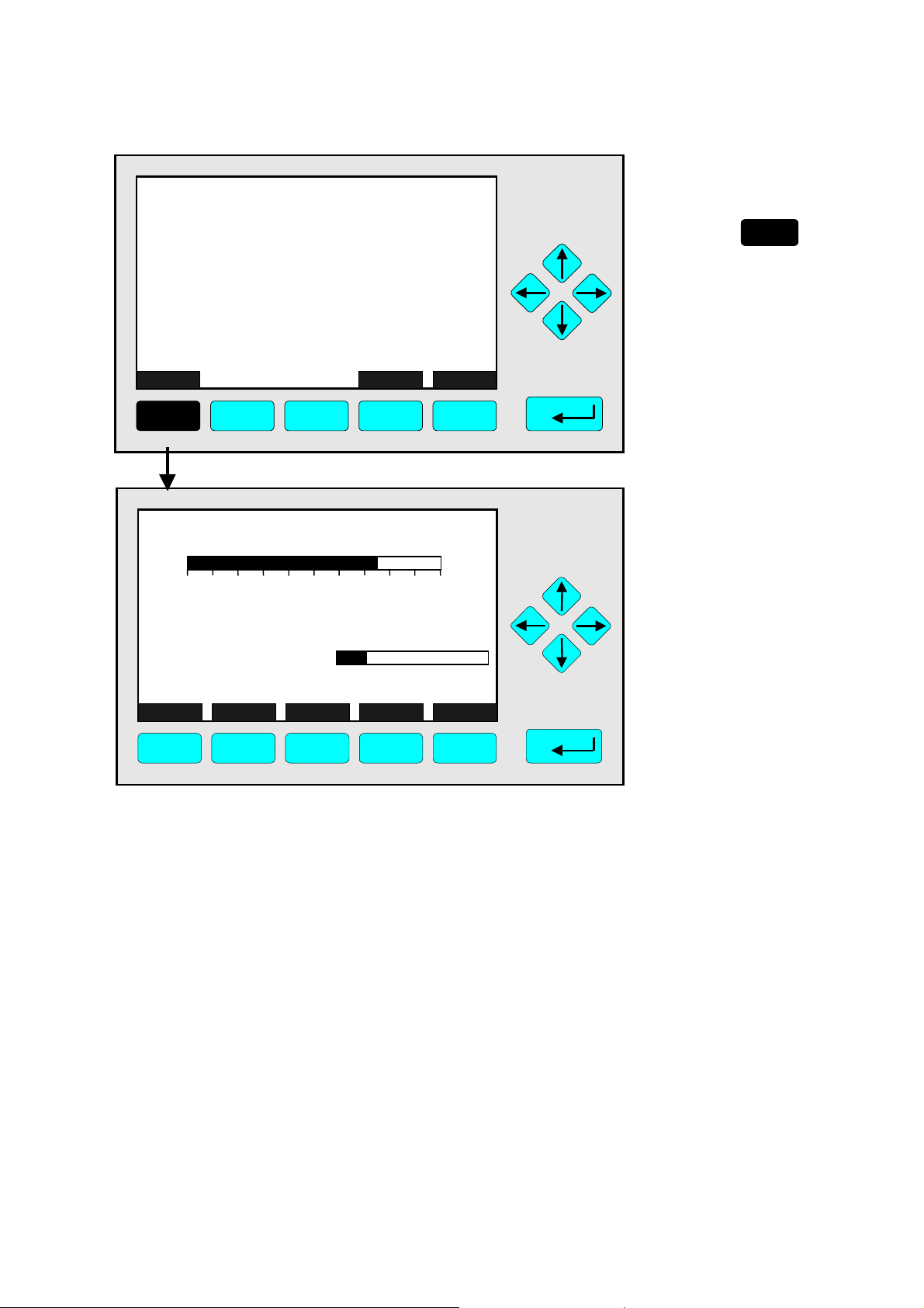
Status Details
e.g. Failures
⇒ Return to the single
component display
F1
Press
TAG
37.50 ppm CH4
0.00 50.00
Failures: No
Maintenance-Requests: No
Temperat ure: 20. 0 C
Operation: Ready
Display Status... Main... Channel
F1 F2 F3 F4 F5
Range: 1
0.0 100.0
⇒ Back in the single
component display
of the current
channel
BasicCal
ETC00612(1) [NGA-e (TFID SW 3.4.X)] 02/01
NGA 2000
4 - 7

4 - 8
NGA 2000
ETC00612(1) [NGA-e (TFID SW 3.4.X)] 02/01
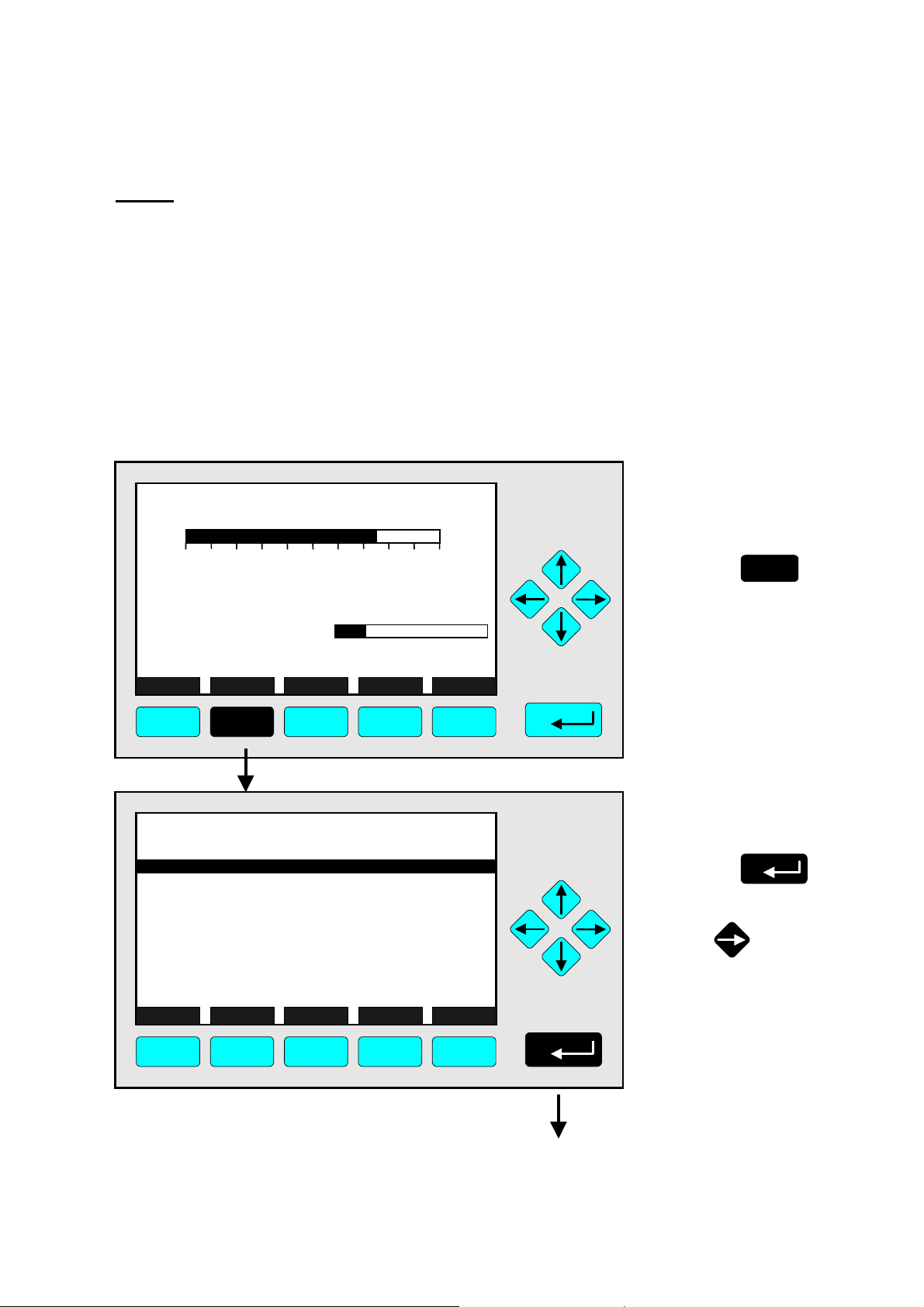
4.1.1 Analyzer Channel Status -
Status Details
e.g. Acknowledge and Clear Failures
Notes:
If you have solved the reasons for the failures reported, you should start this function.
•
The menu "List of Possible Failures" will be ready for new reports!
•
Starting this function is only possible if it is enabled in the menu "Acknowledgement of Status
•
Reports": The line "Acknowledgement allowed in status menu:" has to be set to "Yes"! (see 5.1.9,
pg. 5-53)
Use the same procedure as described below to start the other available functions in the menu
•
"Status Details":
- Acknowledge and clear maintenance requests!
- Acknowledge and clear function controls!
TAG
37.50 ppm CH4
0.00 50.00
Failures: Yes
Maintenance-Requests: No
Temperature: 20.0 C
Operation: Ready
Display Status... Main... Channel BasicCal
F1 F2 F3 F4 F5
TAG
-- Analyzer Channel Status --
Status details...
Current operation parameters...
General status: Normal
Hours of operation: 164
Operation status: Ready
Events: No
Alarms: No
Failures: No
Maintenance requests: No
Function control/Service: No
Measure Channel Back...
RawMeas More...
Range: 1
0.0 100.0
37.50 ppm
⇒ Switch to the menu
"Analyzer Channel
Status"
F2
Press
⇒ Enter the submenu
"Status Details"
Press
or
F1 F2 F3 F4 F5
ETC00612(1) [NGA-e (TFID SW 3.4.X)] 02/01
NGA 2000
4 - 9
TAG
-- Status Details --
Failures...
Maintenance requests...
Function controls...
Alarms...
Events...
Acknowledge and clear failures !
Acknowledge and clear maintenance requests !
Acknowledge and clear function controls !
Measure Back...
37.50 ppm
F1 F2 F3 F4 F5
TAG
-- Status Details --
Failures...
Maintenance requests...
Function controls...
Alarms...
Events...
Acknowledge and clear failures !
Acknowledge and clear maintenance requests !
Acknowledge and clear function controls !
Measure Back...
37.50 ppm
F1 F2 F3 F4 F5
⇒ Highlight the line
"Acknowledge and
clear failures !"
Press
or
as often as necessary
to get the menu line
"Acknowledge and clear
failures !" displayed
inverse.
⇒ Start the function
Press
or
Note:
Starting this function is only
possible if it is enabled in the
menu "Acknowledgment of
Status Reports"
(see 5.1.9 pg. 5-53) !
TAG
-- Confirmation Required --
Do you really want to do this ??
Press "Yes" or "Back..."
Yes Back...
37.50 ppm
F1 F2 F3 F4 F5
4 - 10
NGA 2000
⇒ Confirm the order
Note: Confirmation is only
requested if it is enabled in
menu the expert configurations (s. 5.1.8, pg. 5-49)
F2
Press
to start
the function immediately.
Option:
Press the F4 -key if you
want to cancel the order
and return to the menu
"Status Details".
ETC00612(1) [NGA-e (TFID SW 3.4.X)] 02/01
4.1.1 Analyzer Channel Status -
TAG
- S U C C E S S -
- The selected function has been started/executed (Wait a moment...)
F1 F2 F3 F4 F5
37.50 ppm
Status Details
e.g. Acknowledge and Clear Failures
⇒ Execution message
appears
This message will be displayed when the function
has been started.
The display will return
automatically to the menu
"Status Details".
TAG
-- Status Details --
Failures...
Maintenance requests...
Function controls...
Alarms...
Events...
Acknowledge and clear failures !
Acknowledge and clear maintenance requests !
Acknowledge and clear function controls !
Measure Back...
F1 F2 F3 F4 F5
TAG
37.50 ppm
37.50 ppm CH4
0.00 50.00
Failures: No
Maintenance-Requests: No
Temperature: 20.0 C
Operation: Ready
Range: 1
0.0 100.0
⇒ Return to the single
component display
of the channel
selected
F1
Press
⇒ Back at the single
component display
of the current
channel after
clearing failures
Display Status... Main... Channel BasicCal
F1 F2 F3 F4 F5
ETC00612(1) [NGA-e (TFID SW 3.4.X)] 02/01
NGA 2000
4 - 11
Loading...