

OSEMOUNT ANALYTICAL
R
NGA2000
N
ON
-D
ISPERSIVE INFRARED
A
NALYZER
M
ODULE
748417-A

NOTICE
The information contained in this document is subject to change without notice.
This manual is based on the production version of the Non-Dispersive Infrared Analyzer Module. Hardware
and/or software changes may have occurred since this printing.
Rosemount Analytical's NGA 2000 system of Modular Gas Analyzers and Controllers are patented,
under U.S. Patent 5.787.015.
Pyrex® is a registered trademark of Corning Glass Works
®
Irtran
is a registered trademark of Eastman Kodak Co.
®
Teflon
Ty-Rap
and Viton® is a registered trademark of E.I. duPont de Nemours and Co., Inc.
®
is a registered trademark of Thomas & Betts Corp.
Manual Part Number 748417-A
August 1999
Printed in U.S.A.
Rosemount Analytical Inc.
4125 East La Palma Avenue
Anaheim, California 92807-1802

REFACE
P
Purpose/Safety Summary.................................................................................1
Glossary ....................................................................................................3
Specifications - General...................................................................................5
Specifications - Sample....................................................................................6
Specifications - Physical ...................................................................................6
Customer Service, Technical Assistance and Field Service.............................7
CONTENTS
Returning Parts to the Factory..........................................................................7
Training ....................................................................................................7
Documentation.................................................................................................8
Compliances ....................................................................................................8
ECTION
S
1.1 Overview....................................................................................................1
1.2 Typical Applications...................................................................................1
1.3 Theory of Technology................................................................................2
1.4 Sample Requirements...............................................................................3
1.5 Purge Kits..................................................................................................4
1. I
NTRODUCTION
748417-A
August 1999
1.6 Features....................................................................................................4
Non-Dispersive Infrared Analyzer Module
Rosemount Analytical NGA 2000
i

CONTENTS
ECTION
S
2.1 Unpacking................................................................................................. 7
2.2 Assembly.................................................................................................. 7
2.3 Location ................................................................................................... 8
2.4 Gases ................................................................................................... 9
2.5 Electrical Connections.............................................................................. 11
ECTION
S
3.1 Overview................................................................................................... 15
3.2 Displays SCREENS.................................................................................. 15
2. I
2.4.1 Specifications................................................................................ 9
2.4.2 Connections.................................................................................. 10
3. S
NSTALLATION
TARTUP AND OPERATION
3.2.1 Run Mode Display......................................................................... 15
3.2.2 Menu Displays............................................................................... 15
3.2.3 Help Displays ................................................................................ 16
3.3 Startup Procedure..................................................................................... 16
3.4 Binding ................................................................................................... 19
3.5 Calibration................................................................................................. 19
3.6 Linearization..............................................................................................22
3.7 Routine Operation..................................................................................... 25
Non-Dispersive Infrared Analyzer Module
ii
Rosemount Analytical NGA 2000
748417-A
August 1999

CONTENTS
ECTION
S
4.1 Overview....................................................................................................27
4.2 PCB Replacement.....................................................................................28
4.3 Power Fuse Replacement.........................................................................29
4.4 Module Fan Replacement.........................................................................30
4.5 Chopper Motor Replacement....................................................................31
4.6 Source Replacement.................................................................................31
4.7 Detector Removal......................................................................................32
4.8 Flow Sensor Replacement ........................................................................33
4.9 Case Temperature Sensor Replacement..................................................33
4.10 Thermal Fuse Replacement....................................................................33
4.11 Oscillator Tune/Source Balance Shutter Adjustment ..............................33
4.12 Cleaning Cells.........................................................................................36
4. M
AINTENANCE AND TROUBLESHOOTING
4.13 Cell Desiccant..........................................................................................38
4.14 Modulation Check....................................................................................39
ECTION
S
5.1 Replacement Parts....................................................................................41
748417-A
August 1999
5. R
EPLACEMENT PARTS
Non-Dispersive Infrared Analyzer Module
Rosemount Analytical NGA 2000
iii

CONTENTS
PPENDIX
A
General Precautions For Handling and Storing High Pressure Gas Cylinders
Warranty
Field Service and Repair Facilities
IGURES
F
Figure 1-1. NDIR Technology........................................................................... 3
Figure 1-2. NGA 2000 NDIR Analyzer Module (Typical - Actual
Figure 2-1. Analyzer Module Installation into Instrument Platform.................... 7
Figure 2-2. NDIR Back Panel............................................................................ 10
Figure 2-3. NDIR Front Panel Electrical Connections....................................... 11
Figure 2-4. NDIR Wiring Diagram..................................................................... 12
Figure 2-5 Outline and Mounting Dimensions................................................... 13
Figure 3-1. Run Mode Display.......................................................................... 17
Figure 3-2. Main Menu Display......................................................................... 17
Figure 3-3. Basic Controls Menu....................................................................... 17
Figure 3-4. Expert Controls and Setup Menu.................................................... 18
Figure 3-5. Technical Level Configuration Menu .............................................. 18
Figure 3-6. Typical Help Screen........................................................................ 18
Figure 3-7. Typical Linearization Curve, Linearizer OFF................................... 24
Figure 3-8. Operator-Determined Linearization Curve (Normalized)................. 24
Figure 4-1. Printed Circuit Board Fold-Out Panel Views................................... 28
Figure 4-2. Power Fuse Location...................................................................... 29
Figure 4-3. Fan Assembly................................................................................. 30
Figure 4-4. Motor/Source Assembly.................................................................. 31
Figure 4-5. Cell, PCB Assembly – Exploded View............................................ 32
Figure 4-6. Oscillator Tune, Source Balance Shutter Adjustments................... 35
Figure 4-7. Detector Block (Exploded View) ..................................................... 35
Figure 4.7. Cell Disassembly ............................................................................ 37
A. NDIR I
Configuration May Vary)............................................................... 5
DENTIFICATION MATRIX
Non-Dispersive Infrared Analyzer Module
iv
Rosemount Analytical NGA 2000
748417-A
August 1999

ABLES
T
Table 2-1. Cell Purging Times at Atmospheric Sample Pressure......................8
Table 3-1. NDIR Analyzer Module Alarms.........................................................21
Table 4-1. Cell Desiccant ..................................................................................38
CONTENTS
748417-A
August 1999
Non-Dispersive Infrared Analyzer Module
Rosemount Analytical NGA 2000
v

CONTENTS
NOTES
Non-Dispersive Infrared Analyzer Module
vi
Rosemount Analytical NGA 2000
748417-A
August 1999
PREFACE
PURPOSE/SAFETY SUMMARY
The purpose of this manual is to provide information concerning the components, functions,
installation and maintenance of this particular NGA 2000 module.
Some sections may describe equipment not used in your configuration. The user should
become thoroughly familiar with the operation of this module before operating it. Read this
instruction manual completely.
To avoid explosion, loss of life, personal injury and damage to this equipment
and on-site property, all personnel authorized to install, operate and service this
equipment should be thoroughly familiar with and strictly follow the instructions
in this manual. Save these instructions.
If this equipment is used in a manner not specified in these instructions,
protective systems may be impaired.
DANGER is used to indicate the presence of a hazard which will cause severe personal
injury, death, or substantial property damage if the warning is ignored.
WARNING is used to indicate the presence of a hazard which can cause severe personal
injury, death, or substantial property damage if the warning is ignored.
CAUTION is used to indicate the presence of a hazard which will or can cause minor
personal injury or property damage if the warning is ignored.
NOTE is used to indicate installation, operation or maintenance information which is
important but not hazard-related.
WARNING: ELECTRICAL SHOCK HAZARD
Operate this equipment only when covers are secured. Servicing requires
access to live parts which can cause death or serious injury. Refer servicing to
qualified personnel. For safety and proper performance, this module must be
connected to a properly grounded three-wire source of electrical power.
748417-A
August 1999
Non-Dispersive Infrared Analyzer Module
Rosemount Analytical NGA 2000
P1
PREFACE
WARNING: POSSIBLE EXPLOSION HAZARD
This equipment is not designed for and should not be used in the analysis of
flammable samples. Use of this equipment in this way could result in explosion
and death.
Ensure that all gas connectors are made as labeled and are leak free. Improper
gas connections could result in explosion or death.
WARNING: OVER-VOLTAGE SPIKING
If this Analyzer Module is used with a non-Rosemount Analytical power supply,
adding Rosemount Analytical PN 903341 Current Protector in series with the
24V positive power line will prevent over-voltage spiking and resultant fuse
blowing when powering up the instrument.
CAUTION: PRESSURIZED GAS
This module requires periodic calibration with a known standard gas. See
General Precautions for Handling and Storing High Pressure Gas Cylinders at
the rear of this manual.
CAUTION: HAND INJURY HAZARD
Dropping the front panel of the Platform while hand or fingers are inside either
case handle can cause serious injury.
CAUTION: PARTS INTEGRITY
Tampering with or unauthorized substitution of components may adversely
affect safety of this product. Use only factory approved components for repair.
CAUTION: OVERBALANCE HAZARD
This Analyzer Module may tip instrument over if it is pulled out too far and the
Platform is not properly supported.
Non-Dispersive Infrared Analyzer Module
P2
Rosemount Analytical NGA 2000
NOTE
Apply leak test liquid to cell or detectors only as a last resort.
748417-A
August 1999

PREFACE
GLOSSARY
Analyzer Module
The module that contains all sensor/detector components for development of a Primary
Variable signal; includes all signal conditioning and temperature control circuitry.
Backplane
The interconnect circuit board which the Controller Board, Power Supply, Analyzer Module
power and network cables, I/O Modules and Expansion Modules plug into.
Control Module
The Operator Interface plus the Controller Board.
Controller Board
The computer board that serves as the Network Manager and operates the Display and
Keypad.
Distribution Assembly
The Backplane and the card cages that hold I/O and Expansion Modules.
Expansion Module
A circuit board that plugs into the Backplane from the front of the Platform and performs
special features not related to I/O functions.
I/O Module
A circuit board that plugs into the Backplane from the rear of the Platform. Has a connector
terminal for communication with external data acquisition devices and provides an
input/output function.
Operator Interface
The Display and Keyboard.
Platform
Any workable collection of the following: Controller Board, Power Supply, Distribution
Assembly, Enclosure and Operator Interface.
748417-A
August 1999
Non-Dispersive Infrared Analyzer Module
Rosemount Analytical NGA 2000
P3

PREFACE
Power Supply
Any of a variety of components that provides conditioned power to other NGA 2000
components, from the Power Supply Board that plugs into the front of the Backplane in a
stand-alone instrument to several larger ones that can power larger collections of modules
and components.
Primary Variable
The measured species concentration value from an Analyzer Module.
Secondary Variable
Data placed on the network by a module regarding current status, e.g., sample flow, source
voltage and other diagnostic information.
Softkeys
The five function keys located below the front panel display; they assume the function
displayed directly above each on the display, a function dictated by software.
System
Any collection of Analyzer M odule(s), Platform(s) , I/O Module(s) and Expansion Module( s).
Non-Dispersive Infrared Analyzer Module
P4
Rosemount Analytical NGA 2000
748417-A
August 1999

SPECIFICATIONS - GENERAL
Heteroatomic gases such as ammonia (NH3), carbon dioxide
M
EASUREMENT SPECIES
(CO2), carbon monoxide (CO), carbon monoxide + carbon
:
dioxide ethylene (C2H4), hexane (C6H14), methane (CH4), nitric
oxide (NO) and sulfur dioxide (SO2)
PREFACE
RANGES:
R
EPEATABILITY
M
INIMUM DETECTABLE
L
N
L
R
D
E
T
:
EVEL
:
OISE
INEARITY
ESPONSE TIME
RIFT (ZERO AND SPAN
FFECT OF
EMPERATURE
:
:
:
:
10 ppm fullscale to 100% fullscale (application-dependent); 4
fullscale selections, including suppressed zero ranges
±1% of fullscale (at constant temperature)
0.1% CO2 (at 1 atm. sample pressure; application dependent)
<1% of fullscale, peak-to-peak
±1% of fullscale with 4th order polynomial
.05 to 30 seconds (selectable) for 0 to 90% of fullscale
<±1% of fullscale/24 hours at constant temperature
(application dependent);
):
<±2% of fullscale/week at constant temperature (application
dependent)
<±1% of fullscale over any 10°C interval for rate of change no
greater than 10°C per hour (application dependent)
E
NVIRONMENT
A
MBIENT TEMPERATURE
E
FFECT OF FLOW
P
OWER REQUIREMENTS
748417-A
August 1999
:
:
Location - Class B controlled, indoor, non-hazardous
0 to 45°C (32 to 113°F)
:
<1% of range when sample flow rate is changed by ≤250
ml/min. (No effect if flow rate is between 0 and 500 ml/min.)
24 VDC ±5%, 100 W max.; ripple and noise: <100 mV peak-to-
:
peak; line and load regulations: <±1%
Non-Dispersive Infrared Analyzer Module
Rosemount Analytical NGA 2000
P5

PREFACE
SPECIFICATIONS - SAMPLE
T
EMPERATURE
:
FLOW RATE:
P
RESSURE
P
ARTICULATES
D
EWPOINT
M
ATERIALS IN CONTACT
WITH
S
AMPLE
:
:
:
:
Non-flammable;: 0°C to 55°C (32°F to 138°F)
500 to 1400 ml/min.
Maximum 690 hPa-gauge (10 psig), higher pressure in
pressurized cell applications
filtered to <2 microns
<40°C (104°F), no entrained liquid
Gold plated Pyrex, sapphire, quartz, Irtran, FEP Teflon, Viton-
A, 316 stainless steel
SPECIFICATIONS - PHYSICAL
C
ASE CLASSIFICATION
D
IMENSIONS
:
General purpose for installation in weather-protected areas
:
See Outline and Mounting Dimensions, Figure 2-3
W
M
OUNTING
M
AXIMUM LENGTH OF
LON C
EIGHT
:
:
ABLE
:
Standard: 11 kg (24.2 lbs.); extended: 12.5 kg (27.5 lbs.)
Inside a Platform or custom-installed in a panel
1600 m (1 mile) between Analyzer Module and Platform
See the Preface Section of the Platform manual for specifications regarding Platform
related components.
Non-Dispersive Infrared Analyzer Module
P6
Rosemount Analytical NGA 2000
748417-A
August 1999

PREFACE
CUSTOMER SERVICE, TECHNICAL ASSISTANCE AND FIELD SERVICE
For order administration, replacement Parts, application assistance, on-site or factory
repair, service or maintenance contract information, contact:
Rosemount Analytical Inc.
Process Analytical Division
Customer Service Center
1-800-433-6076
RETURNING PARTS TO THE FACTORY
Before returning parts, contact the Customer Service Center and request a Returned
Materials Authorization (RMA) number. Please have the following information when you
call: Model Number, Serial Number, and Purchase Order Number or Sales Order Number.
Prior authorization by the factory must be obtained before returned materials will be
accepted. Unauthorized returns will be returned to the sender, freight collect.
When returning any product or component that has been exposed to a toxic, corrosive or
other hazardous material or used in such a hazardous environment, the user must attach
an appropriate Material Safety Data Sheet (M.S.D.S.) or a written certification that the
material has been decontaminated, disinfected and/or detoxified.
Return to:
Rosemount Analytical Inc.
4125 East La Palma Avenue
Anaheim, California 92807-1802
TRAINING
A comprehensive Factory Training Program of operator and service classes is available.
For a copy of the Current Operator and Service Training Schedule contact the Technical
Services Department at:
748417-A
August 1999
Rosemount Analytical Inc.
Phone: 1-714-986-7600
FAX: 1-714-577-8006
Non-Dispersive Infrared Analyzer Module
Rosemount Analytical NGA 2000
P7
PREFACE
9
6
DOCUMENTATION
The following Non-Dispersive Infrared Analyzer Module instruction materials are available.
Contact Customer Service or the local representative to order.
748417 Instruction Manual (this document)
COMPLIANCES
This product may carry approvals from several certifying agencies, including Factory Mutual
and the Canadian Standards Association (which is also an OSHA accredited, Nationally
Recognized Testing Laboratory), for use in non-hazardous, indoor locations
FM
APPROVED
Rosemount Analytical Inc. has satisfied all obligations from the European Legislation to
harmonize the product requirements in Europe.
This product complies with the standard level of NAMUR EMC. Recommendation (May
1993).
®
97-C219
NAMUR
This product satisfies all obligations of all relevant standards of the EMC framework in
Australia and New Zealand.
N
Non-Dispersive Infrared Analyzer Module
P8
Rosemount Analytical NGA 2000
748417-A
August 1999

INTRODUCTION
1.1 OVERVIEW
This manual describes the Non-Dispersive Infrared (NDIR) Analyzer Module of Rosemount
Analytical's NGA 200 Series of gas analysis components.
The NDIR Analyzer Module is designed to continuously determine the concentration of
oxygen in a flowing gaseous mixture. The concentration is expressed in one of three
fashions:
• parts-per-million
• percent of composition
• percent of fullscale
The user can obtain an output that is linear with concentration by initiating a linearizer,
which is based on a fourth-order polynomial. The linearizer is incorporated in the Analyzer
Module's electronic circuitry and is adjustable through interconnection with the network.
1
The entire Analyzer Module is designed as a slide-in module (if configured in stand-alone
instrument fashion), removable from the front of the Platform, with gas connections made
from the rear. All electronics relative to sample detection and conditioning are included in
this module.
1.2 TYPICAL APPLICATIONS
The NDIR Analyzer Module is designed to cover a wide range of process, stack and
automotive applications. Typical measurements include:
Chemical and Petroleum
• Carbon dioxide: Manufacture of ethylene oxide, phthalic anhydride and ammonia;
nitrogen generation; and producer gas monitoring
• Carbon Monoxide: Stack monitoring
• Methane: Ammonia manufacture
• Acetylene: Manufacture of acetylene, acrylonitrile, and vinyl chloride
748417-A
August 1999
• Sulfur Dioxide: Sulf uric acid stack gas
Non-Dispersive Infrared Analyzer Module
Rosemount Analytical NGA 2000
1

INTRODUCTION
1
Food and Agriculture
• Carbon Dioxide and Water Vapor: Blanketing of perishables, fermentation
processes, photosynthesis studies, personnel protection
Aerospace and Oceanography
• Carbon Dioxide, Carbon Monoxide, and Water Vapor: Diving and space
chambers
Metals and Ceramics
• Carbon Dioxide: Monitoring of producer gas, steel converting, manufacture of
cement, soaking pit, heat treating
• Carbon Monoxide: Inert gas generation, producer gas monitoring, rotary kiln
roasting, tin plate annealing, steel converting, aluminum power processing,
porcelain kilns, tunnels
• Water Vapor: Heat treating, hydrogen brazing, nickel and chrome plating
• Sulfur Dioxide: Flash smelting
• Ammonia: Ammonia dissociation
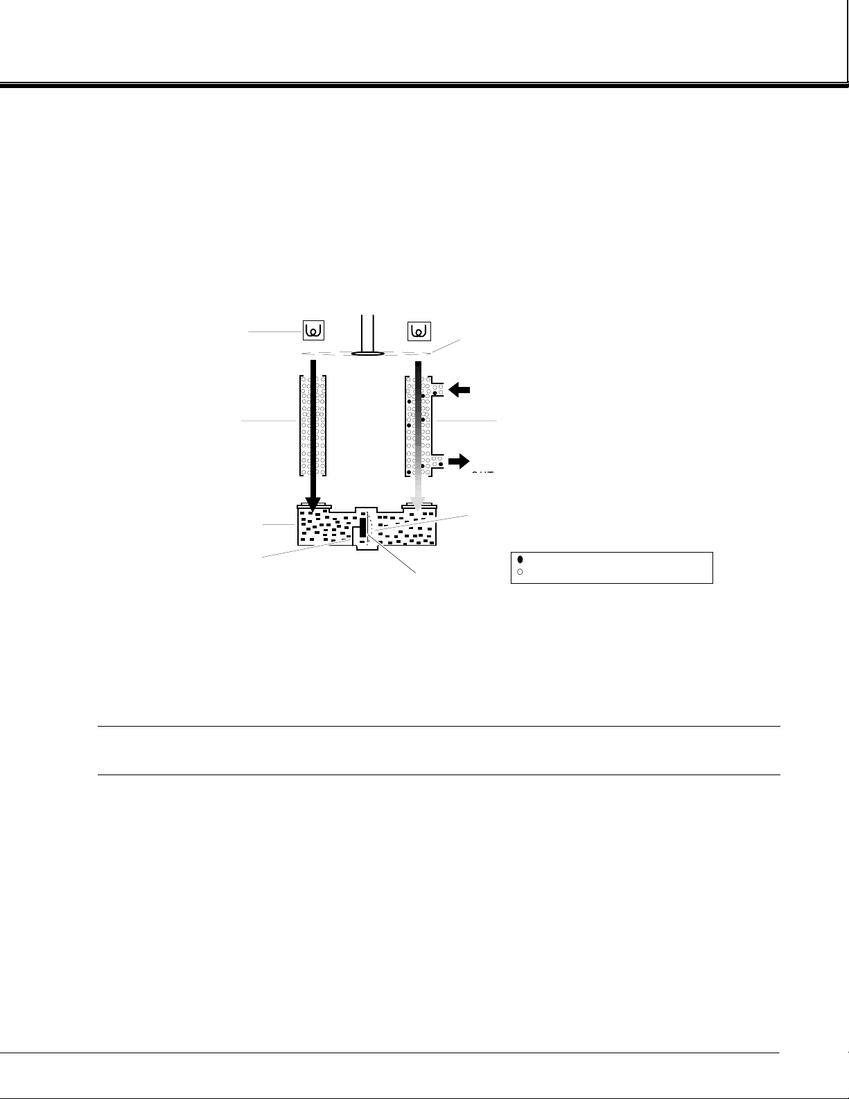
1.3 THEORY OF TECHNOLOGY
Inside of the Analyzer Module, two equal-energy infrared beams are directed through two
parallel optical cells, a flow-through sample cell and a reference cell. The reference cell
may be sealed or may contain a continuously flowing reference gas. (See Figure 1-1.)
The infrared radiation is interrupted by a chopper at a frequency of 5 Hz.
During analysis, a portion of the infrared radiation is absorbed by the component of interest
in the sample. The quantity of infrared radiation that is absorbed is proportional to the
component concentration.
The detector is a "gas microphone" based on the Luft principle. The detector is generally
filled with the same gas being analyzed. The infrared energy is therefore absorbed at the
same wavelengths in the detector as that in the sample cell, making the detector specific for
the analyzed component. The detector converts the difference in energy between sample
and reference cells to a capacitance change. This change, which is proportional to
component concentration, is processed and expressed as the primary variable on the
network.
Non-Dispersive Infrared Analyzer Module
2
Rosemount Analytical NGA 2000
748417-A
August 1999
INTRODUCTION
Other modules comprising the NGA 2000 unit then use this variable for a variety of
purposes (e.g., expressing the gas concentration on the Front Panel Display or sending it to
external data acquisition devices).
For a general understanding of the electrical interconnections in the NDIR Analyzer Module,
see Figure 2-4.
1
IGURE
F
INFRARED
SOURCE
REFERENCE
CELL
DETECTOR
STATIONARY
PLATE
1-1. NDIR T
ECHNOLOGY
CHOPPER
SAMPLE IN
SAMPLE
DIAPHRAGM,
DISTENDED
DIAPHRAGM,
DARK STATE
SAMPLE
CELL
COMPONENT OF INTEREST
NON-INTERFERING COMPOUNDS
1.4 SAMPLE REQUIREMENTS
Maximum allowable sample pressure is 690 hPa-gauge (10 psig) for a standard
configuration NDIR that has a flow restrictor which sets the flow at between 0.5 L/min. to 1
L/min. Special high pressure cells (up to 10,350 hPa-gauge, 150 psig) are available.
Sample temperature range is 0°C to 55°C, and maximum dewpoint is 40°C. The sample
must be filtered to exclude particulates larger than 2 microns in size. Consult factory for
special configurations with specifications outside of those listed above.
748417-A
August 1999
Non-Dispersive Infrared Analyzer Module
Rosemount Analytical NGA 2000
3

INTRODUCTION
1
1.5 PURGE KITS
A purge kit for the motor source or motor source/flowing reference cell accompanies some
NDIR modules. The purpose of these kits is to improve performance and accuracy through
the reduction of ambient CO2 interference. They do not provide protection from
explosion hazard. The purge gas vents into the case, which has no outlet fitting for these
types of purge gases.
1.6 FEATURES
Among the features available in the NDIR Analyzer Module are:
• Pressure compensation for barometric fluctuations (optional)
• Flow sensing
Non-Dispersive Infrared Analyzer Module
4
Rosemount Analytical NGA 2000
748417-A
August 1999
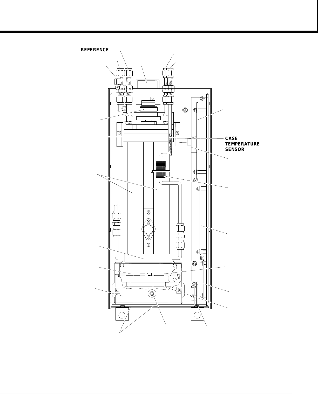
REFERENCE OUT
(
)
REFERENCE IN
PURGE GAS IN
CHOPPER MOTOR
FAN
SAMPLE OUT
(BOTTOM)
SAMPLE IN
INTRODUCTION
POWER SUPPLY
BOARD
1
SOURCE
CELLS
DETECTOR
THERMAL FUSE
DETECTOR COVER
CASE
TEMPERATURE
SENSOR
PRESSURE
COMPENSATION
BOARD
FLOW SENSOR
MICRO BOARD
DETECTOR
TEMPERATURE
CONTROL RTD
SIGNAL BOARD
OPTION
IGURE
F
748417-A
August 1999
SHUTTER ADJUST
ACCESS HOLES
1-2. NGA 2000 NDIR A
ONFIGURATION MAY VARY
C
OSCILLATOR
TUNE ADJUST
NETWORK INPUT
MODULE
NALYZER MODULE (TYPICAL
)
Non-Dispersive Infrared Analyzer Module
OSCILLATOR
BOARD
CTUAL
- A
Rosemount Analytical NGA 2000
5

INTRODUCTION
1
NOTES
Non-Dispersive Infrared Analyzer Module
6
Rosemount Analytical NGA 2000
748417-A
August 1999
INSTALLATION
2.1 UNPACKING
If the NDIR Analyzer Module is received as a separate unit, carefully examine the shipping
carton and contents for signs of damage. Immediately notify the shipping carrier if the
carton or contents is damaged. Retain the carton and packing material until all components
associated with the Analyzer Module are operational.
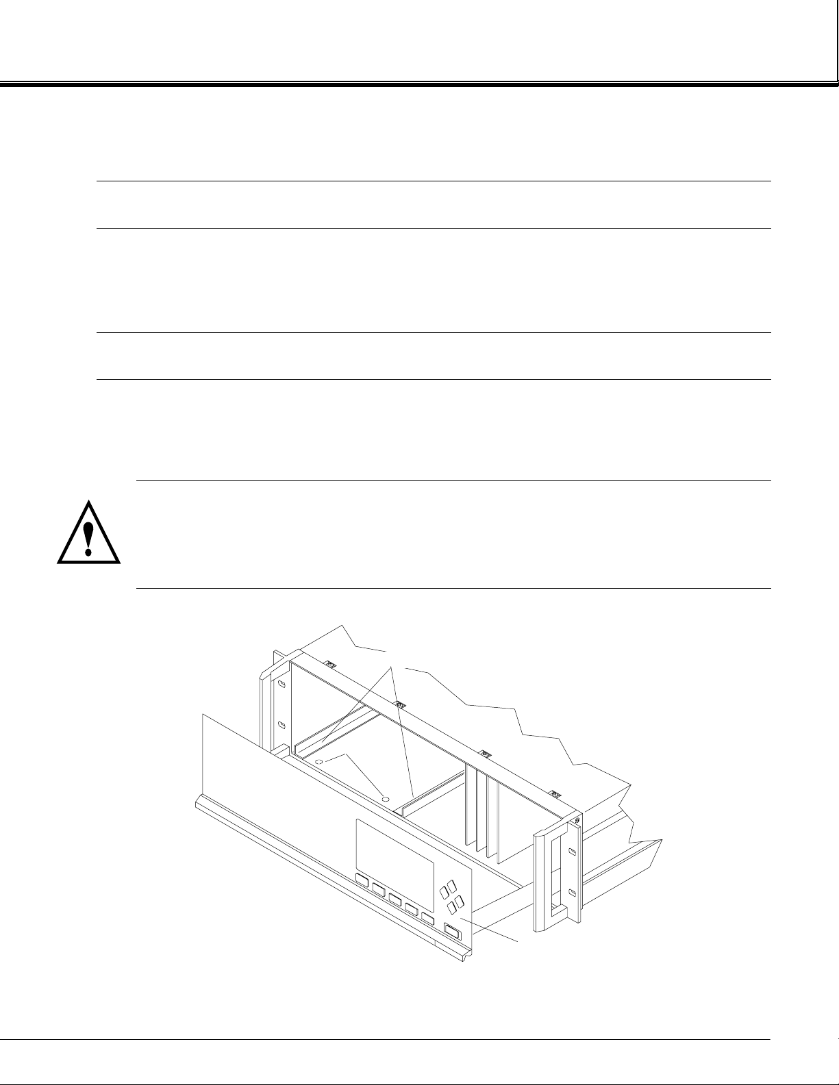
2.2 ASSEMBLY
If the NDIR Analyzer Module requires assembly with other components (e.g., the Platform
and associated I/O Modules), do so at this time. Following the guides on the bottom left and
bottom center of the Platform, carefully slide the Analyzer Module halfway into place.
2
CAUTION: HAND INJURY HAZARD
Do not place hands or fingers in the Platform front handles when front panel is
open. Dropping the front panel of the Platform while hand or fingers are inside
either handle can cause serious injury.
ANALYZER MODULE GUIDES
PIN SEATS
IGURE
F
748417-A
August 1999
2-1. A
DISENGAGED F RONT PANEL
NALYZER MODULE INSTALLATION INTO INSTRUMENT PLATFORM
Non-Dispersive Infrared Analyzer Module
Rosemount Analytical NGA 2000
7
2
INSTALLATION
Lift the spring-loaded pins on the front of the Analyzer Module, and carefully slide it the rest
of the distance. Secure the module in position by releasing the pins, which seat in the
available holes in the bottom of the case (see Figure 2-1). If the module and Platform are
difficult to assemble, remove the module, ensure the top cover of the module is firmly
seated on the hold-down screws, and repeat the assembly procedure.
Install I/O Module(s) according to guidelines in the I/O manual. After startup and calibration
have been performed, secure the front panel with the six screws provided.
2.3 LOCATION
Install the NDIR Analyzer Module in a clean, non-hazardous, weather protected, vibration
free location free from extreme temperature variations. For best results, install the
instrument near the sample stream to minimize sample transport time. Operating ambient
temperature is 0oC to 45oC (32oF to 113oF). Sample dewpoint is 40°C or less.
NOTE
Unrestricted air flow in the rear of the Analyzer Module is critical to its performance
and reliability.
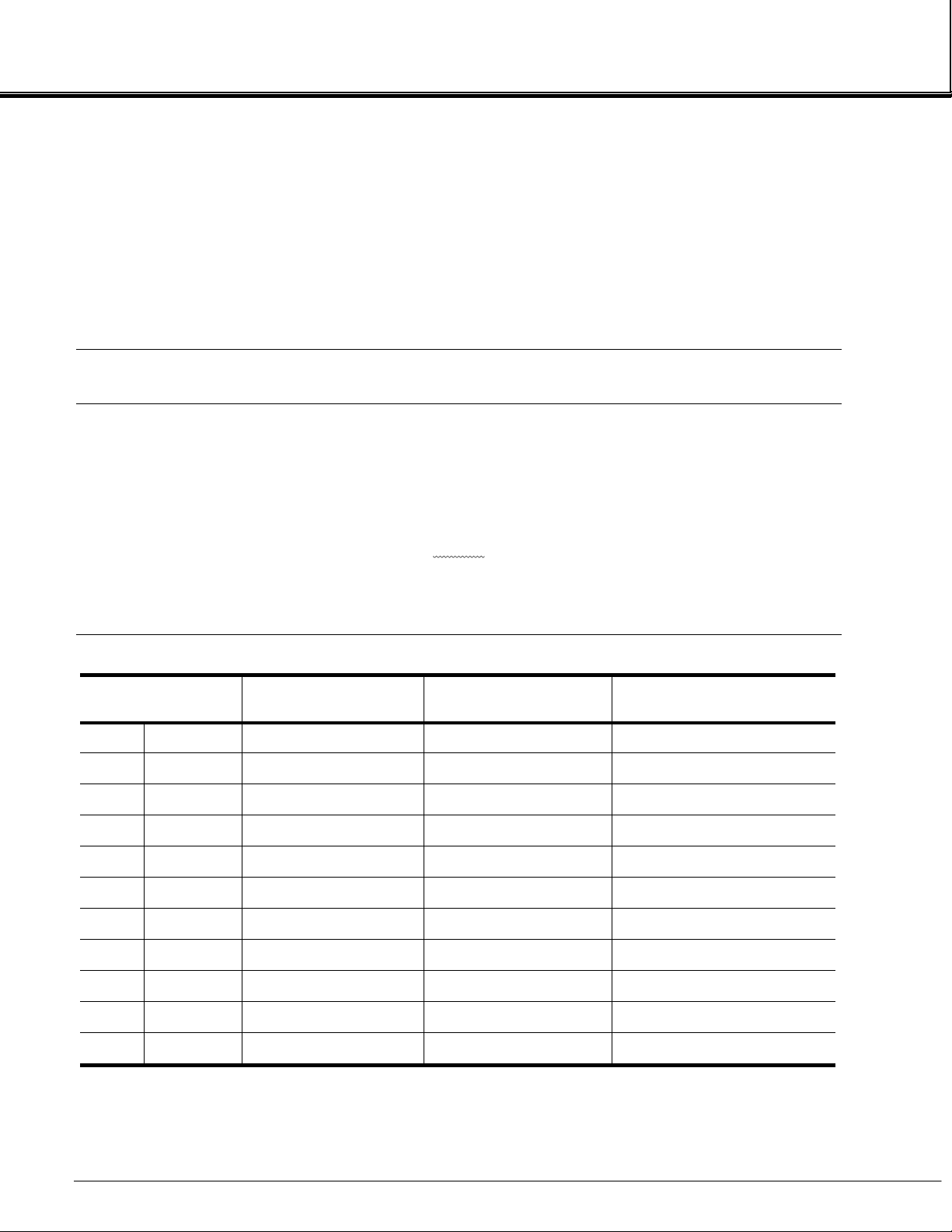
CELL LENGTH
mm inch without inlet tube cell with inlet tube at 750 mm Hg
3 0.118 0.85 12 2 sec.
4 0.157 1.14 12 2 sec.
8 0.315 2.28 13 2 sec.
16 0.630 3.56 16 2 sec.
32 1.25 9.12 20 2 sec.
64 2.52 18.24 25 3 sec.
128 4.03 35.48 44 3 sec.
232 9.13 65.12 73 6 sec.
CELL VOLUME
CC
TOTAL VOLUME
CC
TIME FOR 2 VOLUMES
@ 2 SCFH (1L/MIN)
343 13.50 97.76 105 13 sec.
381 15.00 108.60 116 14 sec.
ABLE
T
Non-Dispersive Infrared Analyzer Module
8
Rosemount Analytical NGA 2000
2-1. C
ELL PURGING TIMES AT ATMOSPHERIC SAMPLE PRESSURE
748417-A
August 1999

2.4 GASES
INSTALLATION
2
2.4.1 S
Calibration Gases
All applications require a zero standard gas to set the zero point on the display and external
data acquisition devices. if the factory provided Calibration and Data Sheet (in the rear of
the manual) specifies a background gas, use this as a zero gas. If a background gas is not
specified, use dry nitrogen.
Span gas should be between 75% and 100% of fullscale span. Flowing reference (if used)
should be dry nitrogen.
Flow Rate
Recommended sample flow rate is 1 to 2 SCFH (500 TO 1000 cc/min). A lower flow rate
will not affect readings but may result in an undesirable time lag. Excessive flow can
produce increases cell pressurization and reading error.
At higher cell pressures, the nonlinearity of the calibration curve increases. Therefore, the
calibration curve should be redrawn for higher flow rates. Also, the effect of increased cell
pressurization can be negated if the same flow rate is used for sample, zero and span
gases. But, if flow is high enough to cause elevated pressure, careful control (tighter
tolerance) of flow rate is required to avoid errors.
PECIFICATIONS
If low is kept at or below 2 SCFH (1 L/min), sample and instrument temperatures reach
equilibrium regardless of stream temperature (within specifications; 0 to 55°C). At
extremely high flow rates, this may not be true, although no such effect has been noted up
to 18 SCFH (9 L/min).
See Table 2-1 for cell purging times at atmospheric sample pressure.
Sample Pressure/Filtration
Sample should be introduced to the Analyzer Module at a maximum 690 hPa-gauge (10
psig). Pressurized applications are available, which require pressurized cells and careful
control of flow rates, consult factory for these applications. Sample should be filtered for
particulates down to two microns.
Leak Test
The Analyzer Module is completely tested at the factory for gas leakage. The user is
responsible for testing for leakage only at the inlet and outlet fittings on the rear panel. The
user is also responsible for internal leak testing periodically and if any internal pneumatic
components are adjusted or replaced (with a test procedure chosen by the user).
748417-A
August 1999
Non-Dispersive Infrared Analyzer Module
Rosemount Analytical NGA 2000
9
2
INSTALLATION
2.4.2 C
ONNECTIONS
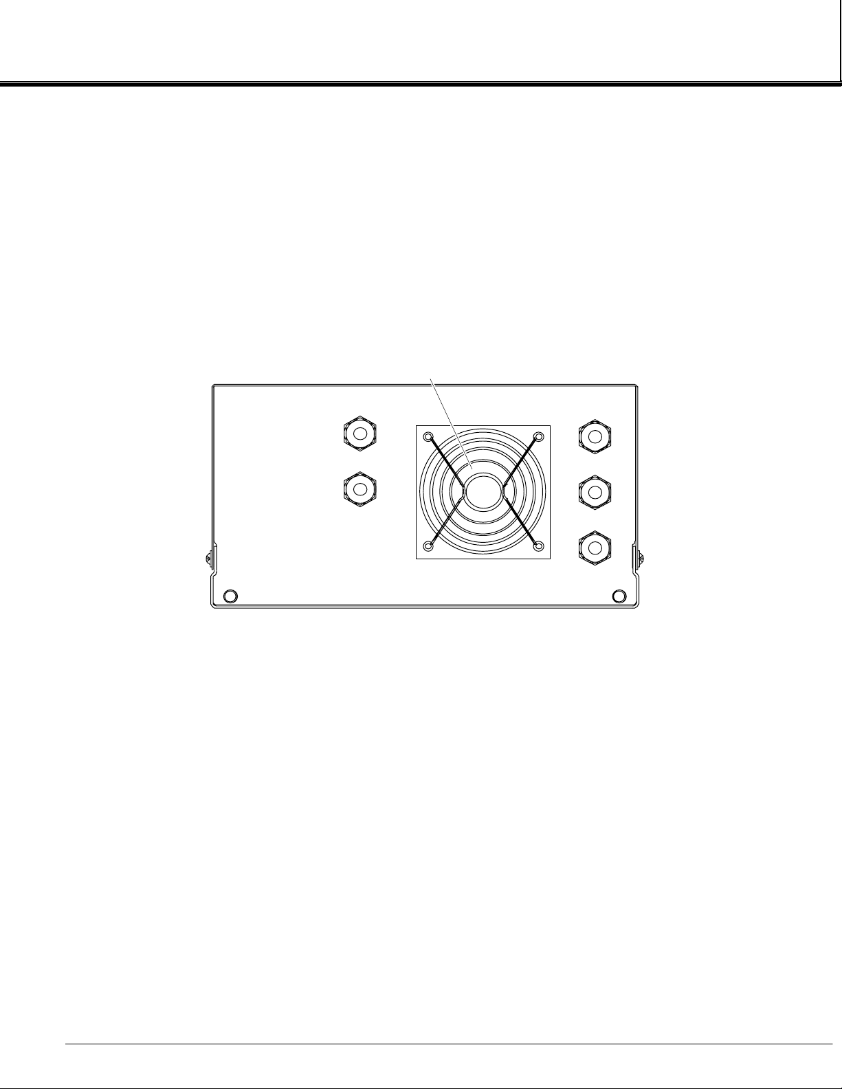
(See Figure 2-2) Connect inlet and outlet lines for sample/zero/span and flowing reference
(if applicable) to appropriately labeled fittings on the rear panel. All four connections are 1/4
inch ferrule-type compression fittings.
FAN
OUT
SAMPLE
IN
10 PSI M AX
(69 kPa MAX)
OUT
REFERENCE
IN
10 PSI M AX
(69 kPa MAX)
IGURE
F
PURGE IN
15 PSI (103 kP a) MAX
Note: Reference and purge gas connections are applicable only to certain applications.
2-2. NDIR B
ACK PANEL
10
Non-Dispersive Infrared Analyzer Module
Rosemount Analytical NGA 2000
748417-A
August 1999

INSTALLATION
2.5 ELECTRICAL CONNECTIONS
NOTE
Electrical connections must be in compliance with National Electrical Code
(ANSI/NFPA 70) and/or any applicable national or electrical codes.
Two electrical connections are required on the Analyzer Module; POWER and NETW ORK.
See Figure 2-3. On the Analyzer Module, two NETWORK connections are available, either
of which is appropriate for : 1) interconnection with Backplane of the Platform (see Platform
instruction manual) or 2) "daisy chaining" with other NGA 2000 components.
Connect Analyzer Module POWER 24 VDC power source, either the Platform or external
power source.
2
IGURE
F
2-3. NDIR F
NETWORK 1
NETWORK 2
POWER
FUSE
RONT PANEL ELECTRICAL CONNECTIONS
748417-A
August 1999
Non-Dispersive Infrared Analyzer Module
Rosemount Analytical NGA 2000
11
2
INSTALLATION
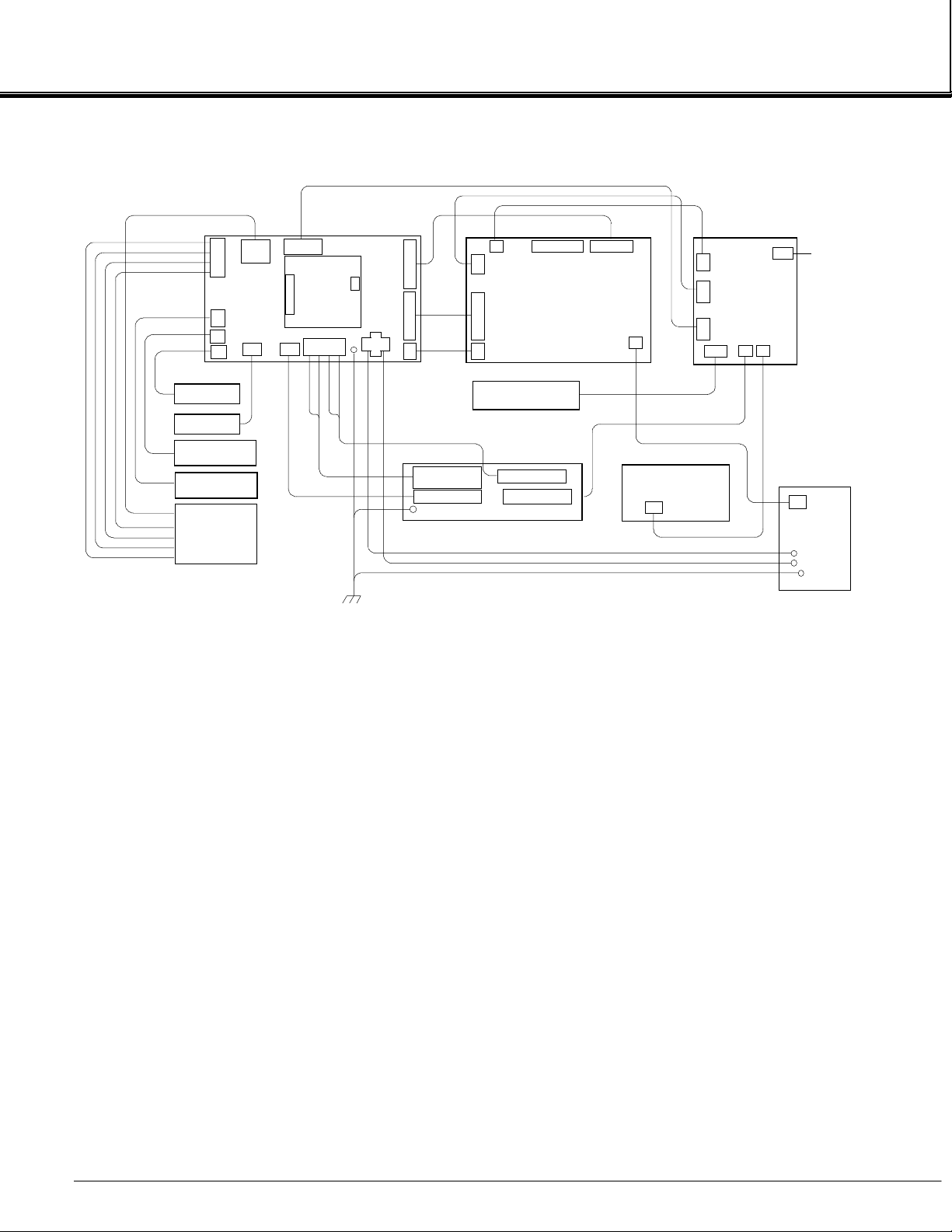
IGURE
F
SAMPLE J2-1
SOURCE J2-2
REFERENCE J2- 3
SOURCE J2-4
J2
J1
J15
J14
FLOW SENSOR
FAN ASSEMBLY
RESISTOR
MODULATION CHECK
HEATSINK/SOURCE
DRIVER
MOTOR ASSEMBLY
REF S O URCE
SOURCE ASSY
SAMPLE SOURCE
J4
POWER
SUPPLY
BOARD
J6 J10
2-4. NDIR W
J9
PRESSURE
COMPEN SATION
BOARD
J7
1 2 3 4
J5
1 2
CHASSIS
GROUND
J11
IRING DIAGRAM
J3
J8
FUSE, THERMAL
CUTOFF
RTD, TEMP CTRL
J4 J5 J6
J1
COMPUTER BOARD
J2
J3
CASE TEMPERATURE
SENSOR
HEATER
DETECTOR BASE
SENSOR °C
RECORDER
J5
J7
SIGNAL
J4
BOARD
BOARD
J6
J3 J1
J2
J7
°°°°
C
OSCILLATOR
J1
OUTPUT
J5
LON/POWER
BOARD
12
Non-Dispersive Infrared Analyzer Module
Rosemount Analytical NGA 2000
748417-A
August 1999
[
]
[28]
4.3
[109]
8.4
[213]
6.2
[157]
8.2
[208]
.6
[15]
2.8
[71]
INSTALLATION
.5
[13]
2
.6
[15]
1.1
1.1
[27]
1.1
[28]
20.0
[508.0]
STANDARD
24.8
[628.7]
EXTENDED
6.0
[152]
STANDARD
8.4
213
17.41
[142.2]
22.41
[569.2]
EXTENDED
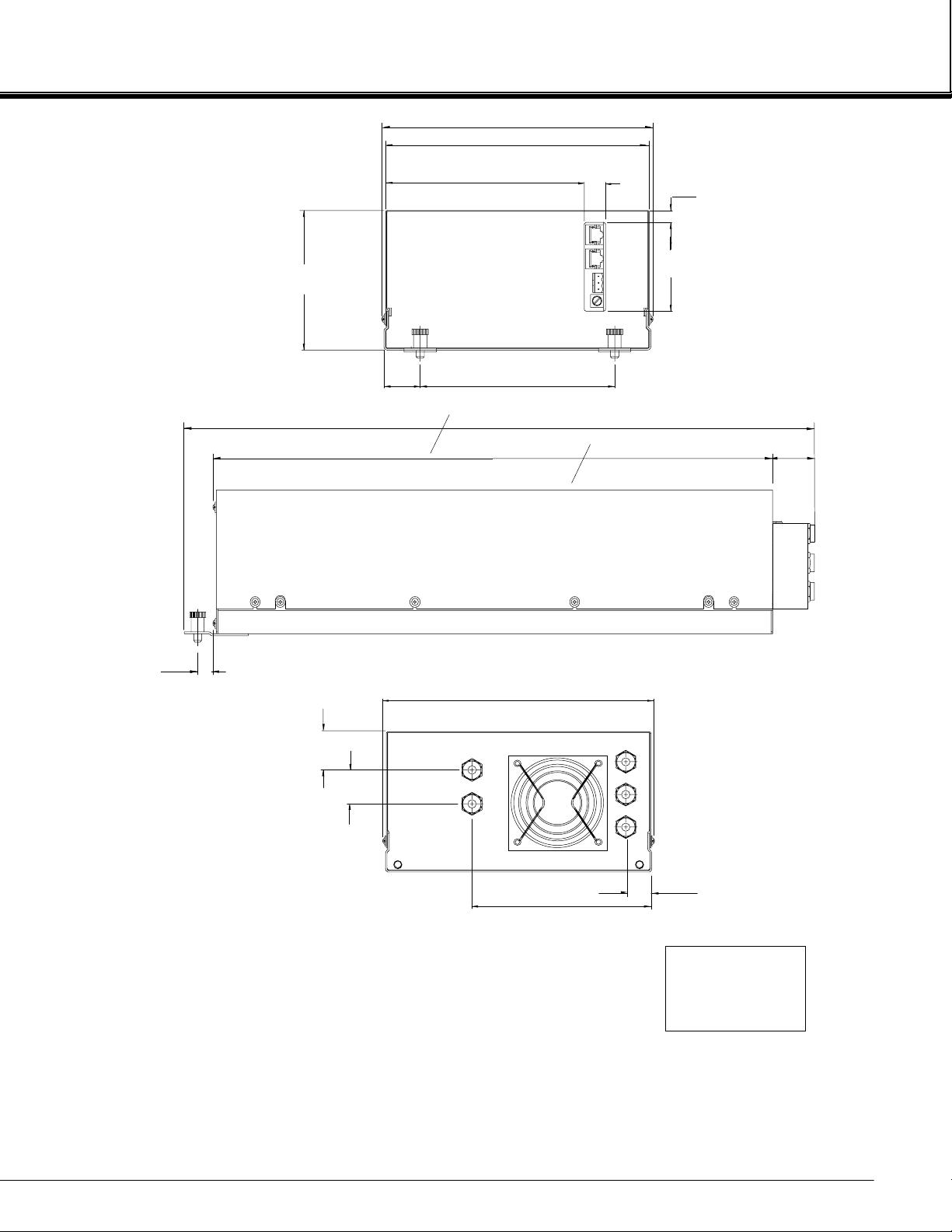
1.6
[40]
G. POWER CABLE TO NETWORK.
F. NETWORK CABLE CONNECTIONS TO PLATFORM.
E. PURGE GAS IN: 1/4" O.D. TUBE FITTING.
D. REFERENCE IN: 1/4" O.D. TUBE FITTING.
C. REFERENCE OUT: 1/4" O.D. TUBE FITTING.
B. SAMPLE OUT: 1/4" O.D. TUBE FITTING.
A. SAMPLE IN: 1/4" O.D. TUBE FITTING.
5. MODULE TO BE IN STALLED WITHIN ±15° OF HORIZONTAL.
4. POWER REQUIREMENTS: 24 VDC 3.5 A.
3. ELECTRICAL INSTALLATION MUST BE IN CO MPLIANCE WITH NATIONAL ELECTRICAL
CODE (ANSI/NFPA 70) AND/O R ANY APPLICABLE NATIONAL OR LOCAL CODES.
2. MODULE IS NOT WEATHERPROOF.
1. APPROXIMATE WEIGHT: 24.2 LB (11.0 kg).
IGURE
F
748417-A
August 1999
2-5 O
UTLINE AND MOUNTING DIMENSIONS
5.6
[143]
1.0
[25]
DIMENSIONS
INCH
[mm]
Non-Dispersive Infrared Analyzer Module
Rosemount Analytical NGA 2000
13

2
INSTALLATION
NOTES
14
Non-Dispersive Infrared Analyzer Module
Rosemount Analytical NGA 2000
748417-A
August 1999
 Loading...