

Manual: NGA 2000 FID Hydrocarbon Analyzer Module SW 3.6 including Hardware-Rev A | Rosemount
Table of contents
 Loading...
Rosemount Manual: NGA 2000 FID Hydrocarbon Analyzer Module SW 3.6 including Hardware-Rev A | Rosemount Manuals & Guides
Instruction Manual
760001-A
October 2002
Model NGA2000 FID
Flame Ionization Detector Module
http://www.processanalytic.com

ESSENTIAL INSTRUCTIONS
READ THIS PAGE BEFORE PROCEEDING!
Rosemount Analytical designs, manufactures and tests its products to meet many national and international standards. Because these instruments are sophisticated technical products, you
MUST properly install, use, and maintain them
normal specifications. The following instructions MUST be adhered to and integrated into your
safety program when installing, using, and maintaining Rosemount Analytical products. Failure to
follow the proper instructions may cause any one of the following situations to occur: Loss of life;
personal injury; property damage; damage to this instrument; and warranty invalidation.
to ensure they continue to operate within their
• Read all instructions
prior to installing, operating, and servicing the product.
• If you do not understand any of the instructions, contact your Rosemount Analytical representative
for clarification.
• Follow all warnings, cautions, and instructions
marked on and supplied with the product.
• Inform and educate your personnel in the proper installation, operation, and maintenance of
the product.
• Install your equipment as specified in the Installation Instructions of the appropriate Instruc-
tion Manual and per applicable local and national codes. Connect all products to the proper elec-
trical and pressure sources.
• To ensure proper performance, use qualified personnel
to install, operate, update, program, and
maintain the product.
• When replacement parts are required, ensure that qualified people use replacement parts specified by
Rosemount. Unauthorized parts and procedures can affect the product’s performance, place the safe
operation of your process at risk, and VOID YOUR WARRANTY
. Look-alike substitutions may result
in fire, electrical hazards, or improper operation.
• Ensure that all equipment doors are closed and protective covers are in place, except when
maintenance is being performed by qualified persons, to prevent electrical shock and personal
injury.
The information contained in this document is subject to change without notice.
Teflon and Viton are registered trademarks of E.I. duPont de Nemours and Co., Inc.
Kynar® is a registered trademark of Pennwalt, Inc.
Tygon is a registered trademark of Saint-Gobain Performance Plastics
Emerson Process Management
Rosemount Analytical Inc.
Process Analytic Division
1201 N. Main St.
Orrville, OH 44667-0901
T (330) 682-9010
F (330) 684-4434
e-mail: gas.csc@EmersonProcess.com
http://www.processanalytic.com

Model NGA2000 FID
TABLE OF CONTENTS
Instruction Manual
760001-A
October 2002
PREFACE...........................................................................................................................................P-1
Definitions ...........................................................................................................................................P-1
Safety Summary .................................................................................................................................P-2
General Precautions For Handling And Storing High Pressure Gas Cylinders .................................P-5
Documentation....................................................................................................................................P-6
Compliances .......................................................................................................................................P-6
Glossary of Terms ............................................................................................................................P-7
1-0 DESCRIPTION AND SPECIFICATIONS..............................................................................1-1
1-1 Overview................................................................................................................................1-1
1-2 Typical Applications...............................................................................................................1-1
1-3 Theory of Technology............................................................................................................1-1
1-4 Gas Safety Features..............................................................................................................1-3
1-5 Fuel Gas Option ....................................................................................................................1-3
1-6 Specifications.........................................................................................................................1-5
a. General ...........................................................................................................................1-5
b. Gas Requirements ..........................................................................................................1-6
c. Physical...........................................................................................................................1-7
d. Gas Connections.............................................................................................................1-7
2-0 INSTALLATION ....................................................................................................................2-1
2-1 Unpacking..............................................................................................................................2-1
2-2 Assembly ...............................................................................................................................2-1
2-3 Location .................................................................................................................................2-2
2-4 Gases ....................................................................................................................................2-3
a. Overview .........................................................................................................................2-3
b. Connections ....................................................................................................................2-3
c. Specifications ..................................................................................................................2-5
d. Leak Test ........................................................................................................................2-6
2-5 Electrical Connections ...........................................................................................................2-6
3-0 OPERATION .........................................................................................................................3-1
3-1 Overview................................................................................................................................3-1
3-2 Displays .................................................................................................................................3-1
3-3 Run Mode Display .................................................................................................................3-1
3-4 Menu Displays .......................................................................................................................3-1
3-5 Help Displays.........................................................................................................................3-1
3-6 Startup Procedure .................................................................................................................3-7
3-7 Binding...................................................................................................................................3-9
3-8 Calibration..............................................................................................................................3-9
3-9 Routine Operation .................................................................................................................3-10
3-10 Safety System .......................................................................................................................3-10
4-0 MAINTENANCE AND SERVICE ..........................................................................................4-1
4-1 Burner disassembly and cleaning .........................................................................................4-1
4-2 Component Replacement......................................................................................................4-2
4-3 Burner Startup Troubleshooting ............................................................................................4-2
Rosemount Analytical Inc. A Division of Emerson Process Management Contents i

Instruction Manual
760001-A
October 2002
5-0 REPLACEMENT PARTS ......................................................................................................5-1
5-1 Replacement Parts ................................................................................................................5-1
a. Electronics.......................................................................................................................5-1
b. Burner Assembly and Components ................................................................................5-1
c. Electro-Mechanical..........................................................................................................5-1
d. O-Rings and Gaskets......................................................................................................5-1
e. Pneumatics .....................................................................................................................5-1
5-2 Matrix .....................................................................................................................................5-2
6-0 RETURN OF MATERIAL ......................................................................................................6-1
6-1 Return Of Material .................................................................................................................6-1
6-2 Customer Service ..................................................................................................................6-1
6-3 Training..................................................................................................................................6-1
7-0 APPENDIX A – MENU SCREENS .......................................................................................7-1
8-0 INDEX....................................................................................................................................8-1
Model NGA2000 FID
ii Contents Rosemount Analytical Inc. A Division of Emerson Process Management

Model NGA2000 FID
LIST OF ILLUSTRATIONS
Figure 1-1. Flame Ionization Detection Technology..........................................................................1-1
Figure 1-2. FID Component Locations – Top View ...........................................................................1-2
Figure 2-1. Analyzer Module Installation into Platform......................................................................2-1
Figure 2-2. Back Panel Connections.................................................................................................2-2
Figure 2-3. FID Module Flow Diagram ..............................................................................................2-4
Figure 2-4. Front Panel Connections, Controls and Indicators .........................................................2-4
Figure 2-5. Outline and Mounting Dimensions..................................................................................2-7
Figure 2-6. FID Wiring Diagram........................................................................................................2-8
Figure 3-1. Run Mode Display...........................................................................................................3-1
Figure 3-2. Main Menu Display..........................................................................................................3-2
Figure 3-3. Basic Controls Menu Display..........................................................................................3-2
Figure 3-4. Expert Controls and Setup Menu Display.......................................................................3-2
Figure 3-5. Technical Configuration Menu Display ...........................................................................3-3
Figure 3-6. Typical Help Screen........................................................................................................3-3
Figure 3-7. Typical Curves of Module Response vs. Pressure Setting on Sample Pressure
Regulator .......................................................................................................................3-5
Figure 3-8. Typical Curves of Module Response vs. Pressure Setting on Fuel Pressure
Regulator .......................................................................................................................3-5
Figure 3-9. Typical Curves of Module Response vs. Pressure Setting on Air Pressure
Regulator .......................................................................................................................3-6
Figure 3-10. Front Panel Torque Sequence........................................................................................3-11
Figure 4-1. FID Burner Assembly – Exploded View..........................................................................4-3
Instruction Manual
760001-A
October 2002
LIST OF TABLES
Table 1-1. Analyzer Characteristics Relative to Fuel Gas ...............................................................1-4
Table 3-1. FID Analyzer Module Alarms ..........................................................................................3-4
Rosemount Analytical Inc. A Division of Emerson Process Management Contents iii

Instruction Manual
760001-A
October 2002
Model NGA2000 FID
iv Contents Rosemount Analytical Inc. A Division of Emerson Process Management

Model NGA2000 FID
The purpose of this manual is to provide information concerning the components,
functions, installation and maintenance of the NGA2000 FID and the System Accessories
of the NGA2000 System.
Some sections may describe equipment not used in your configuration. The user should
become thoroughly familiar with the operation of this module before operating it. Read
this instruction manual completely.
The following definitions apply to DANGERS, WARNINGS, CAUTIONS and NOTES found throughout
this publication.
Instruction Manual
760001-A
October 2002
PREFACE
DEFINITIONS
DANGER .
Highlights the presence of a hazard which will cause severe personal injury, death, or substantial
property damage if the warning is ignored.
WARNING .
Highlights an operation or maintenance procedure, practice, condition, statement, etc. If not
strictly observed, could result in injury, death, or long-term health hazards of personnel.
CAUTION.
Highlights an operation or maintenance procedure, practice, condition, statement, etc. If not
strictly observed, could result in damage to or destruction of equipment, or loss of effectiveness.
NOTE
Highlights an essential operating procedure,
condition or statement.
Rosemount Analytical Inc. A Division of Emerson Process Management Preface P-1

Instruction Manual
760001-A
October 2002
Model NGA2000 FID
SAFETY SUMMARY
If this equipment is used in a manner not specified in these instructions, protective systems may be impaired.
AUTHORIZED PERSONNEL
To avoid explosion, loss of life, personal injury and damage to this equipment and on-site property,
all personnel authorized to install, operate and service the this equipment should be thoroughly
familiar with and strictly follow the instructions in this manual. SAVE THESE INSTRUCTIONS.
DANGER.
ELECTRICAL SHOCK HAZARD
Do not operate without doors and covers secure. Servicing requires access to live parts which can
cause death or serious injury. Refer servicing to qualified personnel. For safety and proper performance this instrument must be connected to a properly grounded three-wire source of power.
WARNING .
POSSIBLE EXPLOSION HAZARD
This equipment is used in the analysis of sample gases which may be flammable, and the burner
fuel used in the ionization process is flammable. A continuous dilution purge system is factory-installed (in accordance with Standard ANSI/NFPA 496-1993, Chapter 6, and it must be functional at all times during operation. Do not disable this purge system.
WARNING .
FLAMMABLE SAMPLES
Consult the factory if flammable samples will be measured.
WARNING.
PARTS INTEGRITY
Tampering or unauthorized substitution of components may adversely affect safety of this product.
Use only factory documented components for repair.
P-2 Preface Rosemount Analytical Inc. A Division of Emerson Process Management

Model NGA2000 FID
Do not place hands or fingers in the Platform front handles when front panel is open. Dropping the
front panel of the Platform while hand or fingers are inside either handle can cause serious injury.
Ensure that all gas connections are made as labeled and are leak free. Improper gas connections
could result in explosion or death.
This module requires periodic use of pressurized gas. See General Precautions for Handling and
Storing High Pressure Gas Cylinders, page P-5.
Instruction Manual
760001-A
October 2002
WARNING.
HAND INJURY HAZARD
WARNING.
POSSIBLE EXPLOSION HAZARD
CAUTION .
PRESSURIZED GAS
CAUTION .
PURGE AIR REQUIREMENT
This Analyzer Module must be used in conjunction with a device (Control Module or PC Interface)
that can actively monitor network variables related to pressure or flow of the continuous dilution
purge, or the front panel LEDs of the Analyzer Module, as installed, must be visible. The purpose of
this requirement is to maintain adherence to ANSI/NFPA 496 standard which assures the continued
viability of the purge system. Under no circumstances should any pressure or flow indicator be
connected to the PURGE AIR OUT outlet of the Analyzer Module because this may affect the sealing
performance of the module.
CAUTION.
OVER-VOLTAGE SPIKING
If this Analyzer Module is used with a non-Rosemount Analytical power supply, adding Rosemount
P/N 903341 Current Protector in series with the 24 V positive power line will prevent over-voltage
spiking and resultant fuse blowing when powering up the instrument.
Rosemount Analytical Inc. A Division of Emerson Process Management Preface P-3

Instruction Manual
760001-A
October 2002
Model NGA2000 FID
CAUTION .
STATIC ELECTRICITY
Circuit boards in this instrument are static-sensitive. Take all static precautions when handling the
circuit boards
NOTE
This Analyzer Module is completely leak-tested at the factory for gas leakage. The user is responsible for testing for leakage at the inlet and outlet fittings on the rear panel (with a test procedure
chosen by the user). The user is also responsible for leak-testing periodically and if any internal
pneumatic components are adjusted or replaced. See leak test instructions in Section2-4d on page
2-6.
P-4 Preface Rosemount Analytical Inc. A Division of Emerson Process Management

Instruction Manual
760001-A
Model NGA2000 FID
October 2002
GENERAL PRECAUTIONS FOR HANDLING AND STORING HIGH
PRESSURE GAS CYLINDERS
Edited from selected paragraphs of the Compressed Gas Association's "Handbook of Compressed
Gases" published in 1981
Compressed Gas Association
1235 Jefferson Davis Highway
Arlington, Virginia 22202
Used by Permission
1. Never drop cylinders or permit them to strike each other violently.
2. Cylinders may be stored in the open, but in such cases, should be protected against extremes of
weather and, to prevent rusting, from the dampness of the ground. Cylinders should be stored in the
shade when located in areas where extreme temperatures are prevalent.
3. The valve protection cap should be left on each cylinder until it has been secured against a wall or
bench, or placed in a cylinder stand, and is ready to be used.
4. Avoid dragging, rolling, or sliding cylinders, even for a short distance; they should be moved by using a
suitable hand-truck.
5. Never tamper with safety devices in valves or cylinders.
6. Do not store full and empty cylinders together. Serious suckback can occur when an empty cylinder is
attached to a pressurized system.
7. No part of cylinder should be subjected to a temperature higher than 125
never be permitted to come in contact with any part of a compressed gas cylinder.
8. Do not place cylinders where they may become part of an electric circuit. When electric arc welding,
precautions must be taken to prevent striking an arc against the cylinder.
°
F (52°C). A flame should
Rosemount Analytical Inc. A Division of Emerson Process Management Preface P-5
Instruction Manual
9
6
760001-A
October 2002
Model NGA2000 FID
DOCUMENTATION
The following NGA2000 FID instruction materials are available. Contact Customer Service Center or the
local representative to order.
760001 Instruction Manual (this document)
COMPLIANCES
This product may carry approvals from several certifying agencies, including Factory Mutual and the Canadian Standards Association (which is also an OSHA accredited Nationally Recognized Testing Laboratory,
NRTL) for use in non-hazardous, indoor locations.
The certification marks appear on the product name-rating plate.
Rosemount Analytical Inc. has satisfied all obligations from the European Legislation to harmonize the
product requirements in Europe.
This product complies with the standard level of NAMUR EMC. Recommendation (May 1993).
This product satisfies all obligations of all relevant standards of the EMC framework in Australia and New
Zealand.
FM
APPROVED
®
97-C219
NAMUR
N
P-6 Preface Rosemount Analytical Inc. A Division of Emerson Process Management

Model NGA2000 FID
GLOSSARY OF TERMS
Analyzer Module
The module that contains all sensor/detector components for development of a Primary Variable signal; includes all signal conditioning and temperature control circuitry.
Backplane
The interconnect circuit board which the Controller Board, Power Supply, Analyzer Module power and network cables, I/O Modules and Expansion Modules plug into.
Control Module
The Operator Interface plus the Controller Board.
Controller Board
The computer board that serves as the Network Manager and operates the Display and Keypad.
Instruction Manual
760001-A
October 2002
Distribution Assembly
The Backplane and the card cages that hold I/O and Expansion Modules.
Expansion Module
A circuit board that plugs into the Backplane from the front of the Platform and performs special features
not related to I/O functions.
I/O Module
A circuit board that plugs into the Backplane from the rear of the Platform. Has a connector terminal for
communication with external data acquisition devices and provides an input/output function.
Operator Interface
The Display and Keyboard.
Platform
Any workable collection of the following: Controller Board, Power Supply, Distribution Assembly, Enclosure
and Operator Interface.
Power Supply
Any of a variety of components that provides conditioned power to other NGA2000 components, from the
Power Supply Board that plugs into the front of the Backplane in a stand-alone instrument to several larger
ones that can power larger collections of modules and components.
Primary Variable
The measured species concentration value from an Analyzer Module.
Secondary Variable
Data placed on the network by a module regarding current status, e.g., sample flow, source voltage and
other diagnostic information.
Rosemount Analytical Inc. A Division of Emerson Process Management Preface P-7

Instruction Manual
760001-A
October 2002
Model NGA2000 FID
Softkeys
The five function keys located below the front panel display; they assume the function displayed directly
above each on the display, a function dictated by software.
System
Any collection of Analyzer Module(s), Platform(s), I/O Module(s) and Expansion Module(s).
P-8 Preface Rosemount Analytical Inc. A Division of Emerson Process Management

Model NGA2000 FID
A
DESCRIPTION AND SPECIFICATIONS
1-1 OVERVIEW
Instruction Manual
760001-A
October 2002
SECTION 1
This manual describes the Flame Ionization
Detector (FID) Analyzer Module of Rosemount Analytical's NGA2000 Series of gas
analysis components. See Figure 1-1 below
and Figure 1-2 on page 1-2.
The FID Analyzer Module is designed to continuously determine the concentration of hydrocarbons in a flowing gaseous mixture. The
concentration is expressed in parts-per-million
or percent of volume.
The entire FID Analyzer Module is designed
as a slide-in module (if configured in
stand-alone instrument fashion), removable
from the front of the Platform, with gas connections made from the rear. All electronics
relative to sample detection and conditioning
are included in this module.
1-2 TYPICAL APPLICATIONS
The monitoring of atmospheric air for low-level
hydrocarbon contaminants and determining
the hydrocarbon content of exhaust emissions
from internal combustion engines are examples of typical applications for the FID Analyzer Module.
1-3 THEORY OF TECHNOLOGY
This Analyzer Module uses the flame ionization method of detection. The sensor is a
burner in which a regulated flow of sample
gas passes through a flame sustained by
regulated flows of a fuel gas (hydrogen or a
hydrogen/diluent mixture) and air.
Within the flame, the hydrocarbon components of the sample stream undergo a complex ionization that produces electrons and
positive ions. Polarized electrodes collect
these ions, causing current to flow through an
electronic measuring circuit
The ionization current is proportional to the
rate at which carbon atoms enter the burner,
and is therefore a measure of the concentration of hydrocarbons in the sample. This
measure of concentration is placed on the
network, where it is can be shown on the Platform Display or on other data acquisition devices.
Negative Ion
Collection
Ring
+90V
Sample
Figure 1-1. Flame Ionization Detection
Technology
Signal
Conditioning
Positive
Carbon
Ions
ir
Fuel
Rosemount Analytical Inc. A Division of Emerson Process Management Description and Specifications 1-1
Instruction Manual
A
760001-A
October 2002
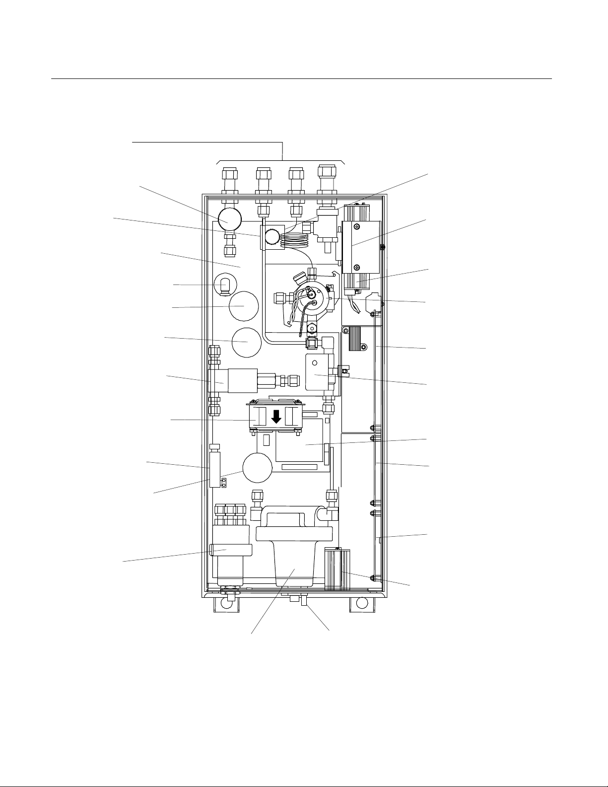
Gas Lines
(See Figure 2-2)
Fuel Shutoff
Solenoid Valve
Capillary
Case Heater Silicon
Pad (On Base)
Purge Air Flow Switch
Fuel Pressure Sensor
Air Pressure Sensor
Ignite/Operate Mode
Burner-Air Flow
Solenoid Valve
ir Circulation Fan
Purge Air
Heater Cartridge
Sample Pressure
Sensor
Burner Air
and Fuel
Regulators
(Stacked Vertically)
Sample Back Pressure Regulators
Model NGA2000 FID
Purge Air
Pressure Regulator
Purge Air Outlet
Pressure Switch
Preamp Board
(In Shield)
Detector (Burner)
Computer Board
Sample Bypass
Flow Sensor
DC-DC Converter
Safety Board
Power Supply Board
Network & Power Module
Manual Ignite Switch
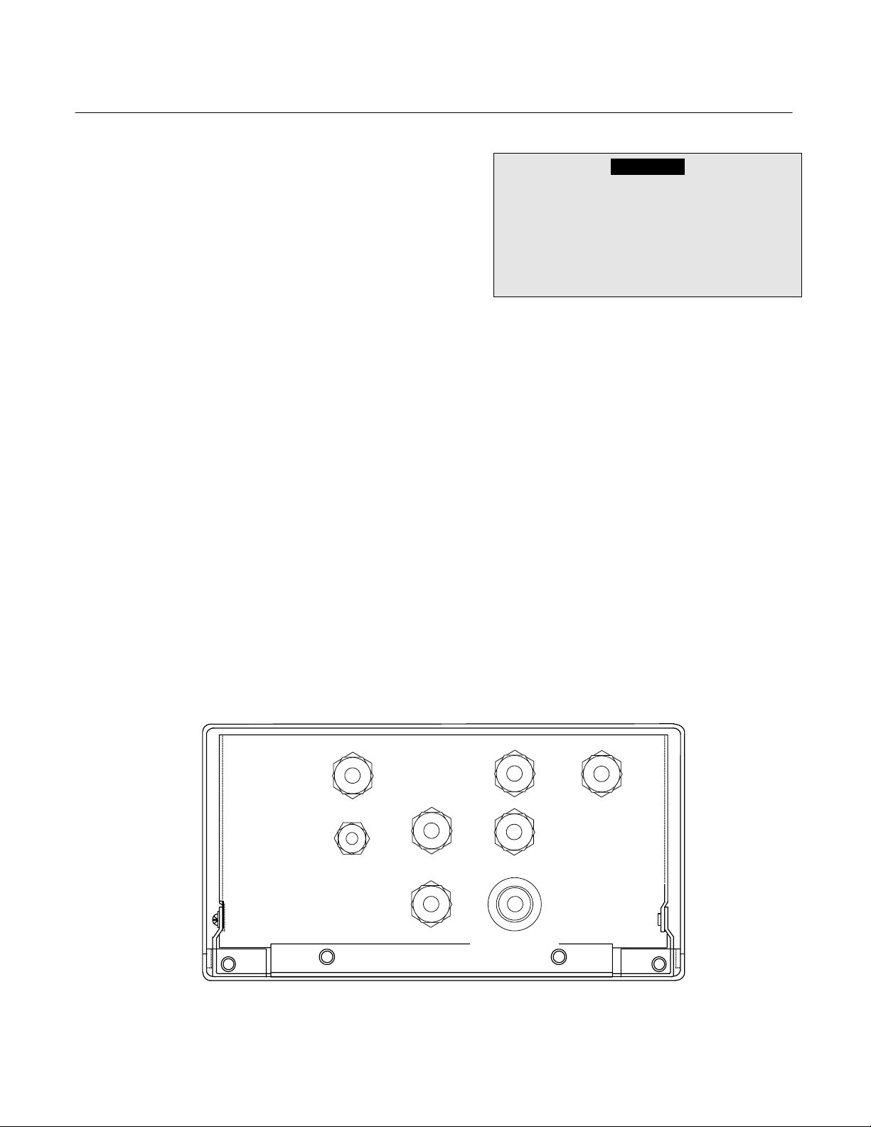
Figure 1-2. FID Component Locations – Top View
1-2 Description and Specifications Rosemount Analytical Inc. A Division of Emerson Process Management

Model NGA2000 FID
1-4 GAS SAFETY FEATURES
The FID Analyzer Module is designed with a
factory installed continuous dilution purge system in accordance with standard ANSI/NFPA
496 - 1993, Chapter 6. Front-panel LEDs indicate that the burner flame is lit and that the
purge system is enabled. In addition, fuel gas
is automatically shut off when a flame-out
condition occurs or the safety system is disabled.
The purge system is enabled only if there is
proper purge gas flow in, purge gas pressure,
and internal case pressure, and after five
times the case volume has been exchanged.
All tubing ahead of the burner is rigid metallic
tubing assembled with ferrule/nut type compression fittings. However, should an internal
fuel leak occur, a worst-case leak would be
dissipated below 25% of the LEL of hydrogen
through the combination of an inlet fuel flow
restrictor and purge gas flow.
This module is designed to use 100% hydrogen fuel or 40% H
mum inlet pressure of 3446 hPa-gauge (50
psig). A different flow restrictor is used for
each fuel type.
A standard FID Analyzer Module is only
equipped to analyze a non-flammable sample,
below 100% of the LEL.
POSSIBLE EXPLOSION HAZARD
Protection against explosion depends
upon a special fuel flow restrictor in the
fuel inlet fitting. Do not remove fuel inlet
restrictor. Use the correct fuel flow restrictor for the fuel being used. Do not use
100% hydrogen fuel in a 40% H2/60% He
configured Analyzer Module. Replace only
with factory supplied fitting.
2/60% He fuel at a maxi-
WARNING
Instruction Manual
760001-A
October 2002
equipped to use 100% hydrogen fuel. The
particular application and characteristics of
the sample gas to be measured will dictate
the preferred type of fuel. The following guidelines can be used for determining fuel gas
type:
1. For measuring low-level hydrocarbons in
ambient air or in other sample gas with
relatively constant oxygen content, 100%
hydrogen is preferable. It provides the
highest obtainable sensitivity and maximum stability. Zero drift caused by ambient temperature variations of the fuel
cylinder is somewhat lower for 100%
hydrogen than for mixed fuel. (With either
fuel, it is desirable to maintain a constant
cylinder temperature.)
2. For monitoring internal combustion exhaust emissions or other sample gas with
varying oxygen content, mixed fuel is
preferable. In fact, a hydrogen/helium
mixture is more desirable than a hydrogen/nitrogen mixture. With this type of
sample, the use of mixed fuel gas minimizes the error introduced by oxygen
synergism.
An effective way to reduce the effect of internal oxygen is to dilute it with an inert gas. This
can be accomplished with a constant dilution
of sample and calibration gases upstream
from the burner. But it is simpler and more accurate to provide that diluent in the form of
premixed fuel. Both nitrogen and helium have
been used as a diluent, but helium has proven
to be most effective in improving the quality of
response to the various species of hydrocarbons.
As indicated earlier the flame output signal is
optimum when the ratio of hydrogen flow to
inert flow is about 40/60. Therefore, this is the
chosen composition for hydrogen/helium premixed fuel.
The sample flow is kept low to maximize the
1-5 FUEL GAS OPTION
The standard FID Analyzer Module requires
40% hydrogen/60% helium burner fuel gas.
As an option, the analyzer module can be
Rosemount Analytical Inc. A Division of Emerson Process Management Description and Specifications 1-3
dilution effect while still providing adequate
sensitivity. The burner air flow is normally
about four times the fuel flow, and changes
have little effect on signal strength. For a

Instruction Manual
760001-A
October 2002
given flow, the signal can be optimized by adjusting the fuel flow rate.
Typical flow rates with premixed fuel:
Model NGA2000 FID
with the latter. However, in any application
where the sample contains more than one
species of hydrogen and/or a varying concentration of oxygen, mixed fuel is preferred.
Fuel 100 cc/min
Sample 7 cc/min
Air 400 cc/min
Note that with a 40/60 premixed fuel, the
above flow rates amount to 40 cc (8%) hydrogen, 67 cc (13%) inert plus sample and 400
cc (79%) air, which compare closely to the 30
cc (8%) hydrogen, 45 cc (12%) inert/sample
and 300 cc (80%) air noted earlier for straight
hydrogen fuel.
Since sample flow in the case of mixed fuel
operation is only about 1/6 of that with straight
hydrogen fuel, higher sensitivity is obtained
ANALYZER FUEL GAS
CHARACTERISTICS 100% H2 40% H2/60% He
Fullscale Sensitivity 1 ppm, CH4 to 2%, CH4 4 ppm, CH4 to <5%, CH4
Fuel Consumption 35 to 40 cc/min 75 to 80 cc/min
Operating Range 276 to 345 hPa-gauge (4 to 5 psig) 207 to 345 hPa-gauge (3 to 5 psig)
Table 1-1. Analyzer Characteristics Relative to Fuel Gas
The mixed fuel is recommended, not only for
sample containing variable concentrations of
oxygen, but also for a specific pure gas application. If straight oxygen samples are used
with straight hydrogen fuel, the mixture entering the burner is essentially 40% H
which tends to produce an unstable signal.
The mixed fuel works better. Note that the
choice of fuel determines certain analyzer
characteristics, as shown in Table 1-1 below.
2/60% O2,
1-4 Description and Specifications Rosemount Analytical Inc. A Division of Emerson Process Management

Model NGA2000 FID
1-6 SPECIFICATIONS
a. General
Measurement Species................... Total hydrocarbons
Ranges .......................................... 0 to 100 ppm (output scalable down to 0-2 ppm
H2/He fuel.............................. low range: 0 to 4 ppm CH
H2 fuel
Repeatability.................................. ≤1% of fullscale at a constant temperature, sample
Minimum Detectable Level
H2/He fuel.............................. 0.04 ppm
H2 fuel
Noise ............................................. ≤1% of fullscale, peak to peak
Linearity ......................................... ≤ ±1% of fullscale for H
Response Time
CEMS .................................... ≤30 sec. For 10% to 90% of fullscale, with sample
ICEE ...................................... ≤1 sec. For 10% to 90% of fullscale, with sample
Zero Drift........................................ ≤ ±1% of fullscale/24 hours at constant
Span Drift....................................... ≤ ±1% of fullscale/24 hours at constant
Effect of Temperature.................... ≤ ±2% of fullscale for any temperature change of
Operating Temperature ................. 32°F to 113°F (0°C to 45°C)
Power Requirements..................... +24 VDC ±5%, 120 W max.. direct to analyzer
1
.................................. low range: 0 to 1 ppm CH4, through 0 to 2500 ppm
1
................................. 0.01 ppm H2 fuel
Instruction Manual
fullscale)
4, through 0 to 1% CH4
high range: 0 to 50 ppm CH4, through 0 to <5%
CH
4
CH4
high range: 0 to 10 ppm CH
CH4
flow and fuel, burner air and sample pressure
bypass flow at 0.5 L/min. (non-flammable sample)
bypass flow at 0.5 L/min. (non-flammable sample)
temperature, hydrocarbon concentration of supply
gases, sample flow and fuel, burner air and sample
pressure
temperature, hydrocarbon concentration of supply
gases, sample flow and fuel, burner air and sample
pressure
10°C and rate of change less than 10°C/hour
module;
Ripple and Noise: <100 mV peak to peak
Line and Load Regulations: <±1%
4, through 0 to 2%
2/He fuel and He fuel
760001-A
October 2002
1
Option
Rosemount Analytical Inc. A Division of Emerson Process Management Description and Specifications 1-5

Instruction Manual
760001-A
October 2002
b. Gas Requirements
Sample .......................................... Non-flammable, below 100% of LEL
Flow rate ................................ 0.5 to 40 ml/min.
THC ....................................... ≤0.5 ppm, CH
Supply pressure..................... 483 to 1035 hPa-gauge (7 to 15 psig)
Temperature .......................... 32°F to 132°F (0°C to 55°C), <20°C variance/24
Particulates............................ Filtered to <2 microns
Dewpoint................................ <45°C
Purge Air........................................ Instrument air, nitrogen or other non-flammable
Flow rate: .............................. 16 to 18 L/min.
Supply pressure:.................... 689 to 1378 hPa-gauge (10 to 20 psig)
Fuel Gas (Standard)...................... Premixed 40% hydrogen and 60% helium
Flow rate ................................ 75 to 80 ml/min.
THC ....................................... ≤0.5 ppm, CH
Supply pressure..................... 2415 to 3450 hPa-gauge (35 to 50 psig)
Model NGA2000 FID
4
hours, <10°C variance/hour
gas (refer to ANSI/NFPA 496 for the requirements
for the Protective Gas System)
4
WARNING
POSSIBLE EXPLOSION HAZARD
Unless this Analyzer Module is factory- or field-configured specifically for using
100% hydrogen fuel, DO NOT USE PURE HYDROGEN FUEL. An explosion resulting
in severe personal injury or death could occur. Also, each Analyzer Module is factory-configured for either mixed or pure hydrogen fuel, and cannot use the fuel for
which it was not configured unless field reconfiguration is done.
Fuel Gas (H2 option) ..................... Zero-grade hydrogen
Flow rate ................................ 35 to 40 ml/min.
THC ....................................... ≤0.5 ppm, CH
Supply pressure..................... 2415 to 3450 hPa-gauge (35 to 50 psig)
Burner Air ...................................... Zero-grade air
Flow rate ................................ 350 to 400 ml/min
THC ....................................... ≤ ppm, CH
Supply pressure............................. 1725 to 3450 hPa-gauge (25 to 50 psig)
4
4
1-6 Description and Specifications Rosemount Analytical Inc. A Division of Emerson Process Management

Model NGA2000 FID
c. Physical
Case Classification:....................... General purpose for installation in
Maximum Separation .................... 1600m (1 mile) from Analyzer Module to Platform
Materials in Contact With Sample . Stainless steel, Teflon, glass-filled Teflon, brass,
Dimensions.................................... See Outline and Mounting Dimensions, Figure 2-5
Weight ........................................... 10.43 kg (23 lbs.)
Mounting........................................ Horizontal, inside a Platform or custom installed in
d. Gas Connections
Sample In: ..................................... 1/4" O.D. tube fitting, stainless steel
Regulated Air In: ..............................1/4" O.D. tube fitting, brass
Burner Air In: ....................................1/4" O.D. tube fitting, brass
Fuel In:..............................................1/4" O.D. tube fitting, stainless steel
Purge Air In: .....................................3/8" O.D. tube fitting, brass
Purge Air Out: ..................................3/8" O.D. tube fitting, brass
Bypass Out:......................................1/4" O.D. tube fitting, stainless steel
Burner Exhaust Out: ........................1/2 inch O.D. tube connection, Tygon or equivalent
Pressure Relief Valve
Instruction Manual
760001-A
October 2002
weather-protected area
neoprene, Kynar
on page 2-7
a panel
(this connection shall slope downward 6° minimum
from horizontal)
CAUTION
PRESSURE RELIEF VALVE RESTRICTION
No connection shall be made to this fitting. If this caution is ignored, damage to the
case seals may occur, and the instrument will not operate properly.
See the Preface section of the Platform Components manual for specifications regarding Platform-related components and the Preface of the I/O Module manual for
specifications regarding I/O (e.g., relay outputs).
Rosemount Analytical Inc. A Division of Emerson Process Management Description and Specifications 1-7

Instruction Manual
760001-A
October 2002
Model NGA2000 FID
1-8 Description and Specifications Rosemount Analytical Inc. A Division of Emerson Process Management
Model NGA2000 FID
A
2-1 UNPACKING
If the FID Analyzer Module is received as a
separate unit, carefully examine the shipping
carton and contents for signs of damage.
Immediately notify the shipping carrier if the
carton or contents is damaged. Retain the
carton and packing material until all
components associated with the Analyzer
Module are operational.
2-2 ASSEMBLY
If the Analyzer Module requires assembly with
other components (e.g., the Platform and
associated I/O Modules), do so at this time.
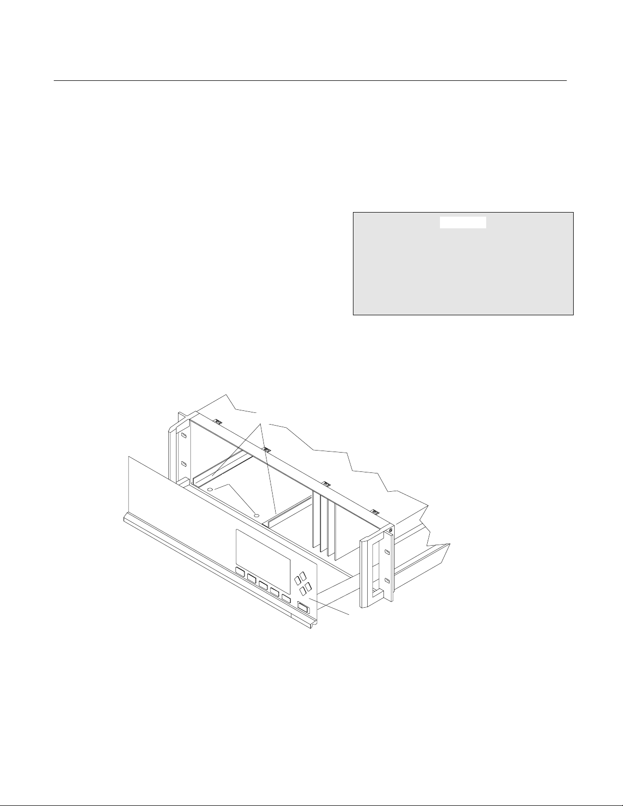
PIN SEATS
Instruction Manual
760001-A
October 2002
SECTION 2
INSTALLATION
Following the guides on the bottom left and
bottom center of the Platform, carefully slide
the Analyzer Module halfway into place.
CAUTION
HAND INJURY HAZARD
Do not place hands or fingers in Platform
front handles when the front panel is open.
Dropping front panel while hand or fingers
are inside either handle can cause serious
injury.
NALYZER MODULE GUIDES
DISENGAGED FRONT PANEL
Figure 2-1. Analyzer Module Installation Into Platform
Rosemount Analytical Inc. A Division of Emerson Process Management Installation
2-1
Instruction Manual
760001-A
October 2002INSTALLATION
Lift the spring loaded pins on the front of the
module, and carefully slide it the rest of the
distance. Secure the module in position by
releasing the pins, which seat in the available
holes in the bottom of the case (see Figure
2-1 on page 2-1). If the module and Platform
are difficult to assemble, remove the module,
ensure the top cover of the module is firmly
seated on the hold down screws, and repeat
the assembly procedure.
Connect the network cable to either the
NETWORK 1 or NETWORK 2 connection on
the Analyzer Module (see Figure 2-4 on page
2-4), and the NETWORK connection on the
Backplane (see Platform manual). Connect
the power cable to both the Analyzer Module
front panel and to the Backplane.
Install I/O Module(s) according to guidelines in
the I/O manual. After startup and calibration
have been performed, secure the Front Panel
with the six screws provided.
Model NGA2000 FID
WARNING
INSTALLATION RESTRICTIONS
For safety, the Analyzer Module should be
installed in a non-confined, ventilated
space. Do not block any of the rear panel
outlets as they are part of the safety
system.
Operating ambient temperature is 0°C to
45°C, limited to temperature changes of less
than 10°C/hr. Acceptable dewpoint range is
less than 95% relative humidity, but not in
excess of 45°C wet bulb temperature.
The cylinders of fuel, air, and calibration
gas(es) and the source of purge air should be
located in an area of relatively constant
ambient temperature.
2-3 LOCATION
Install the Analyzer Module in a clean,
weather-proofed, non-hazardous, vibration
free location free from extreme temperature
variations. For best results, install the
Analyzer Module near the sample stream to
minimize sample transport time.
PURGE
AIR OUT
PRESSURE
RELIEF
VALVE
MIXED
FUEL
IN
BURNER
SAMPLE
IN
PURGE
AIR IN
AIR IN
BYPASS
OUT
VENT TO SAFE AREA
SLOPE DOWNWARD
6 MINIMUM
MAXIMUM INPUT PRESSURE
BURNER AIR: 50 PSIG (3450 hPa)
PURGE AIR: 20 PSIG (1378 hPa)
BURNER
EXHAUST
OUT
FUEL: 50 PSIG (3450 hPa)
SAMPLE: 15 PSIG (1035 hPa)
Figure 2-2. Back Panel Connections
Installation Rosemount Analytical Inc. A Division of Emerson Process Management
2-2

Model NGA2000 FID
2-4 GASES
a. Overview
During normal operation, the Analyzer
Module requires fuel and air to maintain
the burner flame as well as suitable standard gases for calibration and instrument
air for purge requirements. Criteria for selection of these gases follow in 2-4c on
page 2-5.
After initial startup or after startup following a prolonged shutdown, the analyzer
may display baseline drift for a considerable period of time, particularly on the
most sensitive range. Commonly, the drift
is caused by small amounts of hydrocarbons in the inner walls of the tubing in
both the internal flow system and the external gas supply system. Drift results
from any factor influencing the equilibrium
of these absorbed hydrocarbons, such as
temperature or pressure.
Note that this type of drift occurs only
when the flame is burning. If drift occurs
when the flame is extinguished, the electronic circuitry is at fault. To minimize drift,
use clean fuel and air, keep the analyzer
clean, and locate the gas cylinders in an
area of relatively constant ambient temperature.
The cylinders supplying all gases each
should be equipped with a clean, hydrocarbon free, two stage regulator and a
shutoff valve.
All new external gas tubing (except for
PURGE IN/OUT and SAMPLE BYPASS) is
strongly recommended, preferably precleaned, stain-less steel, gas chromatograph
grade tubing. Thoroughly clean before use. if
a hydrocarbon based cleaning solvent
such as acetone is used, purge tubing
with dry nitrogen or helium for several
minutes before using.
Instruction Manual
760001-A
October 2002
Since the oxidation of hydrogen is accompanied by the formation of water vapor, the Exhaust tubing always should be
slanted downward at least 6 degrees from
horizontal. Otherwise, water may accumulate in the line, causing back pressure and
noisy readings, or may back up in the line
and flood the burner.
If the sample is toxic or noxious, or is to
be reclaimed, connect the Bypass outlet
to a suitable disposal system. Do not use
any device that may cause back pressure
in the line.
Purge air and burner air should be supplied from separate sources.
b. Connections
Reference Figure 2-2 on page 2-2. Connect inlet and outlet lines for sample,
burner fuel and air, exhaust, bypass, and
purge to appropriately labeled fittings on
the rear panel. All connections are 1/4
inch ferrule type compression fittings except the PURGE AIR IN and OUT connections, which are 3/8 inch compression
fittings. The BURNER EXHAUST OUT is
a 1/2 inch connection. Burner exhaust,
bypass and purge air out must be vented
at atmospheric pressure to a nonclassified location in accordance with
ANSI/NFPA-496.
It is recommended that no connection be
made to the PURGE AIR OUT port. If,
however, the analyzer's location requires
interconnection with a venting system, the
3/8" O.D. line should be kept as short as
possible, and no longer than four feet.
CAUTION
POSSIBLE INSTRUMENT DAMAGE
No connection should be made to the
PRESSURE RELIEF VALVE fitting. Doing
so may cause damage to the instrument.
Gas line connections are compression fittings. Do not use pipe thread tape.
Rosemount Analytical Inc. A Division of Emerson Process Management Installation 2-3

Instruction Manual
V
760001-A
October 2002
BURNER
EXHAUST
OUT
REGULATOR
Restrictor
PURGE AIR
Plug
1/4MPT
Brass
Run Tee
1/4T - 1/8MPT
Brass
Tubing, Teflon
1/4” OD
PURGE
FLOW
SWITCH
Bulkhead
3/8T
Brass
Tubing, SS
3/8” OD
PURGE AIR
SENSOR
PURGE
AIR
HEATER
Model NGA2000 FID
SAMPLE
IN
IN
CAPILLARY
Tubing, Viton
1/4” OD
PURGE
PRESS
SAMPLE
PRESS
SENSOR
Branch Tee
1/8T - 1/8FPT
SS
SAMPLE
BACK PRESS
REGULATOR
Figure 2-3. FID Module Flow Diagram
BURNER
AIR
!
!
FUEL
Figure 2-4. Front Panel Connections, Controls and Indicators
BYPASS
SAMPLE
Elbow
1/8T - 1/8MPT
Kynar
Connector
1/8T - 1/8MPT
Kynar
WARNING
ATTENTION
OUT
Bulkhead Reducer
1/4T - 1/8T
Brass
Tubing,
Teflon
1/8” OD
FLOW
SENSOR
Tubing,
Teflon
1/8” OD
Elbow
1/8T - 1/4MPT
SS
BURNER
AIR PRESSURE
REGULATOR
SAMPLE
FUEL OVERRIDE
BURNER
AIR IN
Bulkhead Reducer
1/4T - 1/8T
SS
GA
IN OUT
BURNER
AIR
PRESS
SENSOR
POWER
HEAT
FLAME
ON
PURGE
Filter
LON
LON
1 +
AIR
2 -
3 GND
T 6A
260V
COM
3-WAY
VALVE
1
2
IGNITE
Run Tee
1/4T - 1/4FPT
Brass
PURGE AIR
OUT
NC
Run Tee
1/8T - 1/8MPT
SS
FID
WARNING
!
ATTE NTION
!
Bulkhead Connector
1/4T - 1/8NPT
SS
Fuel Restrictor
Purge Exit
Restrictor
PRESS
SW
Connector
1/16T - 1/8MPT
SS
BURNER
MIXED FUEL
IN
SOLENOID
ALVE
Tubing,
Viton
1/4” OD
FUEL
PRESS
SENSOR
Fuel Restrictor
NETWORK 1
NETWORK 2
POWER
FUSE
Connector
1/8T - 1/8MPT
SS
FUEL
PRESSURE
REGULATOR
2-4 Installation Rosemount Analytical Inc. A Division of Emerson Process Management

Model NGA2000 FID
c. Specifications
Fuel Gas
Standard analysis usually requires mixed
fuel, i.e., 40% (±2%) hydrogen and 60%
helium. H2/He mixed fuel is recommended over H2/N2 fuel because of better linearity in concentration output. Such
blends are supplied by many gas vendors
specifically for this use, with a guaranteed
maximum total hydrocarbon content of 0.5
ppm, measured as methane. This specification should be used when obtaining
these mixtures.
NOTE
The fuel restrictor is marked with a red
dot, and the sample capillary is marked
with a red or green dot for mixed fuel
applications.
Some applications require the use of
100% hydrogen fuel. When using this
option, always ensure that sample
pressure (4 to 5 psig) is present when
fuel flow is present. Otherwise, the detector tip may be damaged.
The fuel restrictor and sample capillary
are marked with a white dot for 100%
hydrogen fuel applications.
Burner Air
In order to ensure a low background signal, burner air should contain less than 1
ppm maximum total hydrocarbon content.
An alternate source for burner air and
zero gas (see CALIBRATION GASES below) is a combination diaphragm pump
and heated palladium catalyst. This process continuously removes moderate
amounts of hydrocarbons and carbon
monoxide from ambient air.
Purge Air
Instrument quality air, nitrogen, or other
nonflammable gas is required for the
safety purge system.
Instruction Manual
760001-A
October 2002
Calibration Gases
Calibration method and gases depends
on the type of fuel gas used, the operating
range, and the desired measurement accuracy. In all methods, zero and span
gases are used, and are introduced
through the sample inlet at the rear of the
module.
Z
ERO GAS - Analysis is affected by the
background gas of the sample. Therefore,
it is recommended to use zero gas with as
close to the background composition of
the sample as possible. Normally less
than 0.5 THC as CH
If the burner fuel is 100% hydrogen, the
zero gas, background gas of the sample
or background gas of the span gas cannot
be hydrogen or oxygen. These gases
combined with pure hydrogen fuel would
generate excessive heat in the burner,
causing deterioration of the internal components of the burner.
S
PAN GAS - Span gas consists of a speci-
fied concentration of methane or other
hydrocarbon in a background gas such as
nitrogen. Analysis is affected by the
background gas of the sample. Therefore, span gas containing the same
background gas as the sample is recommended. Then, the background effect is canceled out.
S
AMPLE GAS - Sample gas should be non-
flammable (below 100% of the sample's
LEL). For high sensitivity applications requiring background gas compensation,
contact the factory.
F
LOW RATE - The sample flow rate must
be between 0.5 L/min. and 2 L/min. Flow
rate for purge air should be 16 to 18
L/min.
P
RESSURIZATION/FILTRATION - Sample
pressure at the SAMPLE inlet should be
within the range of 483 to 1035
hPa-gauge (7 to 15 psig), and internally,
should be 345 hPa-gauge (5 psig) nominally. Burner fuel pressures should be:
4 is sufficient.
Rosemount Analytical Inc. A Division of Emerson Process Management Installation 2-5

Instruction Manual
760001-A
October 2002
1725 to 3450 hPa-gauge (25 to 50 psig)
for cylinder regulator, 1518 to
1723 hPa-gauge (22 to 25 psig) internal.
Burner air pressures should be: 1725 to
3450 hPa-gauge (25 to 50 psig) for cylinder regulator, 965 to 1103 hPa-gauge (14
to 16 psig) internal. Purge air (external
supply) pressure should be between 689
and 1378 hPa-gauge (10 and 20 psig),
689 to 827 hPa-gauge (10 to 12 psig)
nominal. The internal purge air regulator
pressure is factory preset at a nominal
setting of 551 hPa-gauge (8 psig) with a
supply pressure of 689 hPa-gauge (10
psig). Noncompliance with these specifications, particularly those concerning
purge air, could cause over-pressure
damage to the module. The nominal internal case pressure is about 0.5 to 1.0
inch of water, and the pressure relief
valve is set at 1/3 psig (nominal).
At the very least, the module's safety system, which requires a certain volume of
purge air flowing through the case before
allowing burner ignition, will not allow the
instrument to operate.
Model NGA2000 FID
for accuracy. Sample should be filtered
for particulates down to two microns.
d. LEAK TEST
The Analyzer Module is completely tested
at the factory for gas leakage. The user is
responsible for testing for leakage at the
inlet and outlet fittings on the rear panel.
The user is also responsible for internal
leak testing periodically and if any internal
pneumatic components are adjusted or
replaced (with a test procedure chosen by
the user).
2-5 ELECTRICAL CONNECTIONS
Two electrical connections are required on the
Analyzer Module: POWER and NETWORK.
See Figure 2-4 on page 2-4. On the Analyzer
Module, two NETWORK connectors are
available, either of which is appropriate for: 1)
interconnection with the Backplane of the
Platform or 2) "daisy-chaining" with other
NGA2000 components. Connect Analyzer
Module POWER to Backplane POWER or external 24 VDC power source.
All internal pressure settings are preset at
the factory, but the operator should check
2-6 Installation Rosemount Analytical Inc. A Division of Emerson Process Management
Model NGA2000 FID
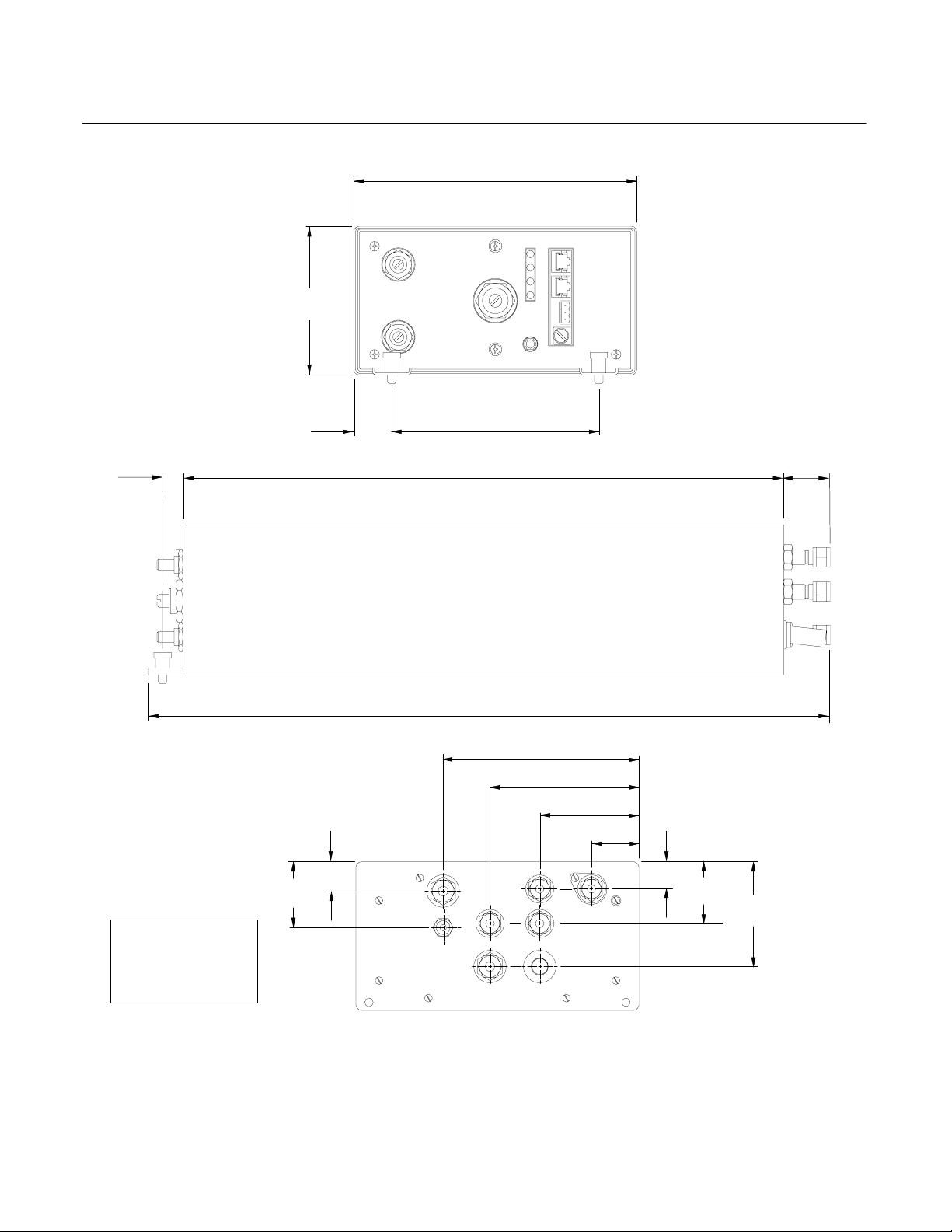
.25
[6.3]
Dimensions:
INCHES
[MM]
4.3
[109.7]
1.1
[27.9]
.9
[22.5]
1.9
[49.4]
Figure 2-5. Outline and Mounting Dimensions
[208.2]
[152.4]
17.75
[450.9]
20.0
[510.0]
8.2
6.0
[143.6]
5.7
4.3
[109.1]
FID
2.9
[73.6]
1.4
[35.6]
.8
[20.9]
D
Instruction Manual
760001-A
October 2002
1.7
[43.4]
1.8
[46.3]
3.1
[78.0]
Rosemount Analytical Inc. A Division of Emerson Process Management Installation 2-7
Loading...