

Rosemount Manual: NGA 2000 FID2 Hydrocarbon Analyzer Module SW 3.3-Rev C | Rosemount Manuals & Guides
OSEMOUNT ANALYTICAL
R
NGA2000
F
LAME IONIZATION
A
NALYZER
D
ETECTOR
M
ODULE
2
748412-C

NOTICE
The information contained in this document is subject to change without notice.
This manual is based on the production version of the Flame Ionization Detector 2 Analyzer Module.
Hardware and/or software changes may have occurred since this printing.
Rosemount Analytical's NGA 2000 system of Modular Gas Analyzers and Controllers are patented,
under U.S. Patent 5.787.015.
Teflon® is a registered trademark of E.I. duPont de Nemours and Co., Inc.
Kynar® is a registered trademark of Pennwalt, Inc.
Manual Part Number 748412-C
October 2000
Printed in U.S.A.
Rosemount Analytical Inc.
4125 East La Palma Avenue
Anaheim, California 92807-1802

REFACE
P
Purpose/Safety Summary.................................................................................P1
Glossary ....................................................................................................P4
Specifications - General...................................................................................P7
Specifications - Gas Requirements..................................................................P8
Specifications - Physical...................................................................................P9
Customer Service, Technical Assistance and Field Service.............................P10
Returning Parts to the Factory..........................................................................P10
CONTENTS
Training ....................................................................................................P10
Documentation.................................................................................................P11
Compliances ....................................................................................................P11
Quick Startup Procedure..................................................................................P13
ECTION
S
1.1 Overview....................................................................................................1
1.2 Typical Applications ...................................................................................2
1.3 Theory of Technology................................................................................2
1.4 Gas Safety Features..................................................................................5
1.5 Fuel Gas Option........................................................................................5
1. I
NTRODUCTION
748412-C
October 2000
Flame Ionization Detector 2 Analyzer Module
Rosemount Analytical NGA 2000
i

CONTENTS
ECTION
S
2.1 Unpacking................................................................................................. 7
2.2 Assembly.................................................................................................. 7
2.3 Location ................................................................................................... 7
2.4 Gases ................................................................................................... 8
2.5 Electrical Connections .............................................................................. 12
2.6 Installation Guidelines............................................................................... 13
ECTION
S
3.1 Overview................................................................................................... 15
NSTALLATION
2. I
2.4.1 Connections.................................................................................. 9
2.4.2 Gas Specifications......................................................................... 9
3. S
TARTUP AND OPERATION
3.2 Displays ................................................................................................... 15
3.2.1 Run Mode Display......................................................................... 15
3.2.2 Menu Displays............................................................................... 16
3.4 Optimization procedure............................................................................. 24
3.5 Binding ................................................................................................... 25
3.6 Calibration................................................................................................. 25
3.7 Calibration details ..................................................................................... 28
3.8 Routine Operation..................................................................................... 29
3.9 Shut down procedure................................................................................ 30
3.10 Safety System......................................................................................... 30
3.11 Alarm indications..................................................................................... 32
3.12 Configuration storage.............................................................................. 33
Flame Ionization Detector 2 Analyzer Module
ii
Rosemount Analytical NGA 2000
748412-C
October 2000

CONTENTS
ECTION
S
4.1 General ....................................................................................................35
4.2 Fuses ....................................................................................................37
4.3 Burner Block Removal And Installation .....................................................38
4.4 Burner Startup And Troubleshooting.........................................................39
4.5 Maintenance schedule...............................................................................42
ECTION
S
5.1 Replacement Parts....................................................................................43
4. M
5. R
AINTENANCE AND TROUBLESHOOTING
EPLACEMENT PARTS
PPENDIX
A
A.1 Gas Safety Features.................................................................................A1
PPENDIX
A
B.1 Analyzer Setup Checklist..........................................................................B1
B.2 Auxiliary module setup..............................................................................B3
B.3 Computer interface setup..........................................................................B3
A. G
B. A
B.1.1 System Setup................................................................................B1
B.1.2 Analyzer Module Setup..................................................................B1
AS SAFETY FEATURES
NALYZER SETUP CHECKLIST
748412-C
October 2000
Flame Ionization Detector 2 Analyzer Module
Rosemount Analytical NGA 2000
iii

CONTENTS
PPENDIX
A
C.1 Instructions............................................................................................... C1
C.2 Menu Items............................................................................................... C1
PPENDIX
A
C. U
D. FID2 I
SER INTERFACE HELP
DENTIFICATION MATRIX
General Precautions For Handling and Storing High Pressure Gas Cylinders
Warranty
Field Service and Repair Facilities
Flame Ionization Detector 2 Analyzer Module
iv
Rosemount Analytical NGA 2000
748412-C
October 2000

IGURES
F
P-1. FID2 Front Panel........................................................................................P14
1-1. FID 2 Analyzer Module...............................................................................1
1-2. Flame Ionization Detection Technology......................................................2
1-3. FID 2 Analyzer Flow Diagram.....................................................................3
2-1. FID 2 Outline and Mounting Dimensions....................................................9
2-2. FID 2 Rear Panel........................................................................................10
2-3. FID 2 Front Panel......................................................................................12
3-1. Run Mode Display......................................................................................15
3-2. Main Menu..................................................................................................16
3-3. Basic Controls Menu..................................................................................17
3-4. Expert Controls Menu.................................................................................17
3-5. Analyzer Module Setup Menu ....................................................................18
3-6. Typical Help Menu......................................................................................18
3-7. Analyzer Diagnostics Menu........................................................................19
3-8. Self Test Results Menu..............................................................................20
3-9. Light Flame Menu.......................................................................................21
3-10. Typical Curves of Module Response vs. Pressure Setting on
Sample Pressure Regulator..........................................................22
3-11. Typical Curves of Module Response vs. Pressure Setting on
Fuel Pressure Regulator...............................................................23
3-12. Typical Curves of Module Response vs. Pressure Setting on
Air Pressure Regulator..................................................................23
3-13. Typical Calibration Gas List Menu............................................................25
3-14. Zero and Span Calibration Menu..............................................................26
3-15. Calibration Parameters Menu...................................................................26
3-16. Z
ERO/SPAN DIAGNOSTIC DATA
....................................................................26
3-17. Analyzer Manufacturing Data Menu .........................................................29
3-18. Store/Restore User Settings Menu...........................................................33
3-19. Store Historical Data Menu.......................................................................34
4-1. Locations Of Major Components Of The FID2 ...........................................35
4-2. Removal Of FID2 Cover.............................................................................36
4-3. Main Power Fuse........................................................................................ 36
4-4. Fuse Locations On Module Board..............................................................37
4-5. Physical Measurement Parameters Menu..................................................39
4-6. FID 2 – Exploded View...............................................................................40
4-7. Burner Block – Exploded View...................................................................41
4-8. Burner ......................................................................................................42
CONTENTS
748412-C
October 2000
Flame Ionization Detector 2 Analyzer Module
Rosemount Analytical NGA 2000
v

CONTENTS
ABLES
T
1-1. Gas Flow Rates......................................................................................... 6
1-2. Analyzer Characteristics Relative to Fuel Gas........................................... 6
2-1. Gas Supply Pressures............................................................................... 11
3-1. FID 2 Analyzer Module Alarms .................................................................. 32
A-1. Typical Flow Rates With Premixed Fuel.................................................... A1
A-2. Analyzer Characteristics For Different Fuels............................................. A1
Flame Ionization Detector 2 Analyzer Module
vi
Rosemount Analytical NGA 2000
748412-C
October 2000
CONTENTS
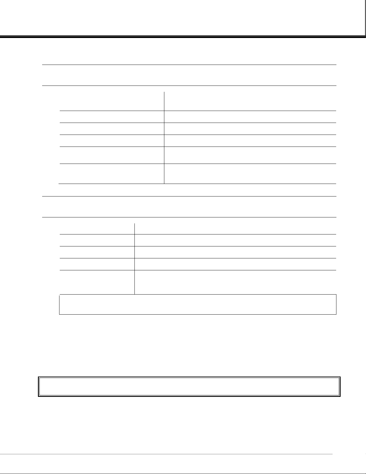
PURPOSE/SAFETY SUMMARY
The purpose of this manual is to provide information concerning the components, functions,
installation and maintenance of this particular NGA 2000 module.
Some sections may describe equipment not used in your configuration. The user should
become thoroughly fa miliar with the operation of this mo dule before opera ting it. Read this
instruction manual completel y .
To avoid explosion, loss of life, personal injury and damage to this equipment
and on-site property, all personnel authorized to install, operate and service this
equipment should be thoroughly familiar with and strictly follow the instructions
in this manual. Save these instructions.
If this equipment is used in a manner not specified in these instructions,
protective systems may be impaired.
DANGER is used to indicate the presence of a hazard which will cause severe personal
injury, death, or substantial property damage if the warning is ignored.
WARNING is used to indicate the presence of a hazard which can cause severe personal
injury, death, or substantial property damage if the warning is ignored.
CAUTION is used to indicate the presence of a hazard which will or can cause minor
personal injury or property damage if the warning is ignored.
NOTE is used to indicate installation, operation or maintenance information which is
important but not hazard-related.
WARNING: ELECTRICAL SHOCK HAZARD
Operate this equipment only when covers are secured. Servicing requires
access to live parts which can cause death or serious injury. Refer servicing to
qualified personnel. For safety and proper performance, this module must be
connected to a properly grounded three-wire source of electrical power.
748412-C
October 2000
Flame Ionization Detector 2 Analyzer Module
Rosemount Analytical NGA 2000
vii

PREFACE
WARNING: POSSIBLE EXPLOSION HAZARD
This equipment is used in the analysis of sample gases which may be
flammable, and the burner fuel used in the ionization process IS flammable. A
system of intrinsically safe electronics and an explosion proof tower are used to
prevent any ignition of a flammable gas leak. For this to be effective, the module
MUST be placed in a well-ventilated area, with unobstructed air flow around it.
DO NOT place it within another enclosure without assuring this ventilation.
DO NOT obstruct the vent holes on the top and sides of the module.
DO NOT place the FID module within another enclosure unless the latter has a
guaranteed air circulation such as to dilute a worst case fuel or sample leak
below 25% of the LEL. Doing so will negate the safety features and may result in
an explosion, serious injury, property damage and death.
WARNING: FLAMMABLE SAMPLES
Consult the factory if flammable samples will be measured.
WARNING: PARTS INTEGRITY
Tampering with or unauthorized substitution of components may adversely
affect safety of this product. Use only factory-approved components for repair.
WARNING: POSSIBLE EXPLOSION HAZARD
Ensure that all gas connections are made as labeled and are leak free. Improper
gas connections could result in explosion and death.
WARNING: STATIC ELECTRICITY
Circuit boards in this instrument are static-sensitive. Take all static precautions
when handling the circuit boards.
Flame Ionization Detector 2 Analyzer Module
P2
Rosemount Analytical NGA 2000
748412-C
October 2000

PREFACE
WARNING: POSSIBLE EXPLOSION HAZARD
Protection against explosion depends upon a special fuel flow restrictor in the
fuel inlet fitting. DO NOT REMOVE THE FUEL INLET RESTRICTOR. Use the
correct fuel flow restrictor for the fuel being used. Do not use 100% hydrogen
fuel in a 40% H2/60% He configured FID module. Replace with factory supplied
fitting only.
CAUTION: PRESSURIZED GAS
This module requires calibration with a known standard gas. See General
Precautions for Handling and Storing High Pressure Gas Cylinders at the rear of
this manual.
CAUTION: OVERBALANCE HAZARD
This Analyzer Module may tip instrument over if it is pulled out too far and the
Platform is not properly supported.
CAUTION: CONTROLLED ENVIRONMENT
This equipment is for use in a controlled environment. Refer to the
specifications (page P7) in this manual for environmental conditions.
CAUTION: HOT OVEN COMPONENTS
The oven and sample manifold are controlled to 80
down before touching any of these components.
NOTE
This Analyzer Module is completely leak-tested at the factory for gas leakage. The
user is responsible for testing for leakage at the inlet and outlet fittings on the rear
panel (with a test procedure chosen by the user). The user is also responsible for
leak-testing periodically and if any internal pneumatic components are adjusted or
replaced. See leak test instructions on page 2-5.
°°°°
C. Allow the analyzer to cool
748412-C
October 2000
Flame Ionization Detector 2 Analyzer Module
Rosemount Analytical NGA 2000
P3

PREFACE
GLOSSARY
Analyzer Module
The module that contains all sensor/detector components for development of a Primary
Variable signal; includes all signal conditioning and temperature control circuitry.
Backplane
The interconnect circuit board which the Controller Board, Power Supply, Analyzer Module
power and network cables, I/O Modules and Expansion Modules plug into.
Control Module
The Operator Interface plus the Controller Board.
Controller Board
The computer board that serves as the Network Manager and operates the Display and
Keypad.
Diluent
The material used to dilute another material. In air, nitrogen is the diluent for the oxygen we
need to breathe.
Distribution Assembly
The Backplane and the card cages that hold I/O and Expansion Modules.
Expansion Module
A circuit board that plugs into the Backplane from the front of the Platform and performs
special features not related to I/O functions.
Flame Ionization
A technique for measuring hydrocarbon gases. A flame is used to ionize the carbon atoms,
and the charge thus generated is measured.
Gas Chromatography
A technique of separating gas stream components using absorption media, allowing the
detector to measure individual species within the stream.
Flame Ionization Detector 2 Analyzer Module
P4
Rosemount Analytical NGA 2000
748412-C
October 2000

PREFACE
Hydrocarbon
A chemical containing only hydrogen and carbon atoms. Methane, propane and octane are
hydrocarbons.
Hydrocarbons
Organic molecules containing just carbon and hydrogen. Methane, propane and oils are
example of hydrocarbons.
I/O Module
A circuit board that plugs into the Backplane from the rear of the Platform. Has a connector
terminal for communication with external data acquisition devices and provides an
input/output function.
Ionization
Generation of electrically charged particles from a neutral material. In the FID, the flame
causes hydrocarbon molecules to split into such charged ions.
LED
Light Emitting Diode – a solid state indicator light.
Operator Interface
The Display and Keyboard.
Platform
Any workable collection of the following: Controller Board, Power Supply, Distribution
Assembly, Enclosure and Operator Interface.
Power Supply
Any of a variety of components that provides conditioned power to other NGA 2000
components, from the Power Supply Board that plugs into the front of the Backplane in a
stand-alone instrument to several larger ones that can power larger collections of modules
and components.
Primary Variable
The measured species concentration value from an Analyzer Module.
748412-C
October 2000
Flame Ionization Detector 2 Analyzer Module
Rosemount Analytical NGA 2000
P5

PREFACE
Purge
A safety system that uses an air flow to keep any fuel gas leak under the lower explosive
limit (LEL).
Sample Conditioning
The process of altering the state of the sample gas so as to make it suitable for an analyzer.
This includes removing condensable water, changing the pressure, and filtering.
Secondary Variable
Data placed on the network by a module regarding current status, e.g., sample flow, source
voltage and other diagnostic information.
Softkeys
The five function keys located below the front panel display; they assume the function
displayed directly above each on the display, a function dictated by software.
Species
A particular gas within a mixture. Oxygen is a species in air.
Subnode
A subsection of the analyzer devoted to measuring one of the species for which it is set up.
Analyzers with multiple subnodes can measure multiple gases.
System
Any collection of Analyzer Module(s), Platform(s), I/O Module(s) and Expansion Module(s).
Flame Ionization Detector 2 Analyzer Module
P6
Rosemount Analytical NGA 2000
748412-C
October 2000

SPECIFICATIONS - GENERAL
PREFACE
M
EASUREMENT SPECIES
H2/HE FUEL
R
EPEATABILITY
MINIMUM DETECTABLE LEVEL
N
OISE
L
INEARITY
R
ESPONSE TIME
Z
ERO DRIFT
S
PAN DRIFT
E
FFECT OF TEMPERATURE
O
PERATING TEMPERATURE
Total hydrocarbons
low range: 0 to 4 ppm CH4, through 0 to 1% CH
high range:: 0 to 50 ppm CH4, through 0 to <5% CH
4
4
≤1% of fullscale at a constant temperature, sample flow
and fuel, burner air and sample pressure
0.04 ppm H2/He fuel – methane equivalent
≤1% of fullscale, peak to peak
≤ ±1% of fullscale for H2/He fuel and H2 fuel
<1 second for bypass flow rate of 500 cc/min (for a
sample change at the rear panel connector of the
instrument)
≤ ±1% of fullscale/24 hours at constant temperature,
hydrocarbon concentration of supply gases, sample flow
and fuel, burner air and sample pressure
≤ ±1% of fullscale/24 hours at constant temperature,
hydrocarbon concentration of supply gases, sample flow
and fuel, burner air and sample pressure
≤ ±2% of fullscale for any temperature chang e o f 10°C
and rate of change less than 10°C/hour
41°F to 104°F (5°C to 40°C)
O
PERATING HUMIDITY
P
OWER REQUIREMENTS
748412-C
October 2000
<95% relative humidity, non-condensing
+24 VDC ±5%, 120 W max.. direct to analyzer module;
Ripple and Noise: <100 mV peak to peak
Line and Load Regulations: <±1%
Flame Ionization Detector 2 Analyzer Module
Rosemount Analytical NGA 2000
P7
PREFACE
SPECIFICATIONS - GAS REQUIREMENTS
B
URNER AIR
F
LOW RATE
THC
S
UPPLY PRESSURE
F
UEL GAS (STANDARD
F
LOW RATE
THC
S
UPPLY PRESSURE
Hydrocarbon free grade air
350 to 400 ml/min
≤0.1 ppm CH
4
1725 to 3450 hPa-gauge (25 to 50 psig)
Premixed 40% hydrogen and 60% helium
)
110 to 110 ml/min.
≤0.5 ppm CH
4
3101 to 3450 hPa-gauge (45 to 50 psig)
WARNING: POSSIBLE EXPLOSION HAZARD
DO NOT USE PURE HYDROGEN FUEL. An explosion res ulting in severe
personal injury or death could occur. Also, each Analyzer Module is
factory-configured for mixed, and cannot use the fuel for which it was not
configured unless field reconfiguration is done.
S
AMPLE
F
LOW RATE
S
UPPLY PRESSURE
T
EMPERATURE
P
ARTICULATES
D
EWPOINT
Non-flammable (below 100% of LEL)
0.5 to 2.0 L/min.
483 to 1035 hPa-gauge (7 to 15 psig)
32°F to 248°F (0°C to 120°C), <20°C variance/24 hours,
<10°C variance/hour
Filtered to <2 microns
<45°C
Flame Ionization Detector 2 Analyzer Module
P8
Rosemount Analytical NGA 2000
748412-C
October 2000
SPECIFICATIONS - PHYSICAL
M
ATERIALS IN CONTACT WITH
SAMPLE
PREFACE
Stainless steel, Teflon, glass-filled Teflon, Viton
D
IMENSIONS
W
EIGHT
M
OUNTING
C
ASE CLASSIFICATION
MAX. S
P
EPARATION FROM
LATFORM
See Figure 2-5, Outline and Mounting Dimensions
10.43 kg (23 lbs.)
Horizontal
General Purpose for installation in weather
protected area
1600 m (1 mile)
SPECIFICATIONS - GAS CONNECTIONS
S
AMPLE IN
B
URNER AIR IN
F
UEL IN
B
YPASS OUT
B
URNER EXHAUST
O
UT
1/4 inch O.D. tube fitting
1/4 inch O.D. tube fitting
1/4 inch O.D. tube fitting
1/4 inch O.D. tube fitting
3/8 inch O.D. tube slip-fit connection, tygon or equivalent
(this connection shall slope downward 6° minimum from
horizontal)
T
HE BURNER EXHAUST AND BYPASS OUT SHALL BE VENTED TO ATMOSPHERIC PRESSURE
AND TO A NON
-
CLASSIFIED LOCATION
.
See the Preface Section of the Platform manual for specifications regarding Platform related
components.
748412-C
October 2000
Flame Ionization Detector 2 Analyzer Module
Rosemount Analytical NGA 2000
P9

PREFACE
CUSTOMER SERVICE, TECHNICAL ASSISTANCE AND FIELD SERVICE
For order administration, replacement Parts, application assistance, on-site or factory repair,
service or maintenance contract information, contact:
Rosemount Analytical Inc.
Process Analytical Division
Customer Service Center
1-800-433-6076
RETURNING PARTS TO THE FACTORY
Before returning parts, contact the Customer Service Center and request a Returned
Materials Authorization (RMA) number. Please have the following information when you call:
Model Number, Serial Number, and Purchase Order Number or Sales Order Number.
Prior authorization by the factory must be obtained before returned materials will be
accepted. Unauthorized returns will be returned to the send er, freight collect.
When return ing any product or compon ent that has been expo sed to a toxic, co rrosive or
other hazardous material or used in such a hazardous environment, the user must attach an
appropriate Material Safety Data Sheet (M.S.D.S.) or a written certification that the material
has been decontaminated, disinfected and/or detoxified.
Return to:
Rosemount Analytical Inc.
4125 East La Palma Avenue
Anaheim, California 92807-1802
USA
T
RAINING
A comprehensive Factory Training Program of operator and service classes is available.
For a copy of the Current Operator and Service Training Schedule contact the Technical
Services Department at:
Flame Ionization Detector 2 Analyzer Module
P10
Rosemount Analytical NGA 2000
Rosemount Analytical Inc.
Phone: 1-714-986-7600
FAX: 1-714-577-8006
748412-C
October 2000

PREFACE
DOCUMENTATION
The following Flame Ionization Detector 2 Analyzer Module instruction materials are
available. Contact Customer Service or the local representative to order.
748412 Instruction Manual (this document)
C
OMPLIANCES
This product may carry approvals from several certifying agencies, like The Canadian
Standards Association (CSA), which is also an OSHA accredited Nationally Recognized
Testing Laboratory (NRTL), and LCIE - a French Notified Body.
The certification marks appear on the product name-rating plate.
NRTL /C
®
LCIE 98 ATEX 6004 X
EEx d ib IIB (+H
0°C Ta +40°C
Date of Manufacture:
0081
) T6
2
II 2 G
Rosemount Analytical has satisfied all obligations from the European Legislation to
harmonize the product requirement in Europe.
This product complies with the standard level of NAMUR EMC
NAMUR
Recommendations (1993).
This product satisfies all obligations of all relevant standards of the EMC framework in
Australia and New Zealand.
N96
748412-C
October 2000
Flame Ionization Detector 2 Analyzer Module
Rosemount Analytical NGA 2000
P11

PREFACE
NOTES
Flame Ionization Detector 2 Analyzer Module
P12
Rosemount Analytical NGA 2000
748412-C
October 2000
PREFACE
QUICK STARTUP PROCEDURE
The purpose of this reference guide is to provide a easy to follow, step by step procedure
through initial start up and ignition of the FID2 Analyzer Module. This procedure assumes
that the customer has already made all necessary electrical and gas connections and
established the proper network connections.
1. Turn on power to the instrument. The #1 LED (POWER) will illuminate. The #3 LED
(BLOCK) will begin flashin g.
2. If sample gas has been connected and the sample pressure to the analyzer is sufficient
to provide an accurate reading, the #4 LED (SAMPLE) will be illumninated.
3. Allow the analyzer module to warm up and the burner block temperature to reach the
proper minimum ignition temperature (50°C). When the burner block temperature
reaches the minimum ignition temperature, the #5 LED (IGNITE OK) will come on.
4. The instrument is now ready to be lit. Lighting the burner can be conducted in one of
two methods: a) manual ignition from the front panel of the Analyzer Module or b)
autoignite from the Platform.
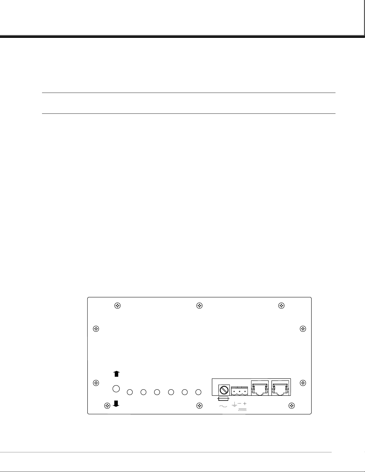
FID 2
F
IGURE
748412-C
October 2000
FUEL OVERRIDE
IGNITE
P-1. FID2 F
POWER FLAME BLOCK SAMPLE IGNITE FUEL/AIR
OK
RONT PANEL
3 2 1 LON2 LON1
T 6A
24V
Flame Ionization Detector 2 Analyzer Module
Rosemount Analytical NGA 2000
P13

PREFACE
a. To light the instrument from the Analyzer Module, hold the "FUEL
b. To light the instrument from the Platform using the autoignite mode, simply press
OVERRIDE/IGNITE" switch (located to the left of the indicator lights) in the up
(FUEL OVERRIDE) position for 30 seconds. Immediately move the switch to the
down (IGNITE) position. The "IGNITE" mode is automatically set to stay on for a
preset time period and does not require the switch to be held down. If the lighting
procedure was successful, the #2 LED (FLA ME) will begin flashing as the flame
temperature rises to the correct operating temperature. Once this LED becomes
solidly lit, the flame has reached operating temperature.
the "light" softkey shown in the "Light Flame" menu of the Platform. The Analyzer
Module will begin to go through an automated sequence of enrichment and
ignition similar to the manual mode described in step 5. If the burner fails to light
on the first try, the Analyzer Module will perform 2 more tries before terminating
the autoignite sequence. If the Analyzer Module fails to light after 3 attempts, an
error message will be displayed sho wing the cause of the fault.
5. If the burner fails to light, check all gas connections for proper gas composition and
pressure, block temperature, and outlets for obstructions. Repeat step 4.
6. If the flame is lit, the #2 LED will begin flashing. Once the flame temperature has
reached the correct operating temperature, the LED will remain on solid.
7. If the fuel and air pressures and ratios are within proper operating parameters to
support a continuous flame operation, the # 6 LED (FUEL/AIR) will illuminate. This light
will not be on before or during flame ignition.
8. Once the burner block temperature reaches the control temperature of 80°C, the #3
LED will stay on solid.
9. If the instrument has been successfully lit, the temperatures are up to proper operating
levels, and the fuel, air, and sample gases are properly adjusted to support the flame
and achieve reliable results, all 6 indicator lights will be lit solid.
The unit is now ready for calibration or burner optimization.
Flame Ionization Detector 2 Analyzer Module
P14
Rosemount Analytical NGA 2000
748412-C
October 2000

INTRODUCTION
1.1 OVERVIEW
This manual describes the Flame Ionization Detector (FID2) Analyzer Module of Rosemount
Analytical's NGA 2000 Series of gas analysis components. See Figure 1-1.
The FID2 Analyzer Module is designed to use a flame ionization technique to measure the
total concentration of hydrocarbon (including certain oxygenated hydrocarbons)
components within the sample stream.
The entire FID2 Analyzer Module is designed as a module with electrical connections at its
front, and gas connections made from the rear. All electronics relative to sample control and
signal conditioning are included in this module.
1
FRONT
Intrinsic Safety Board
Module Board
Computer Board
Regulator
Burner
Oven
(Cover removed)
REAR
Flow Control Manifold
F
IGURE
748412-C
October 2000
1-1. FID2 A
NALYZER MODULE
Flame Ionization Detector 2 Analyzer Module
Rosemount Analytical NGA 2000
1

1
+++
+
+
INTRODUCTION
1.2 TYPICAL APPLICATIONS
Typical applications for the FID2 Analyzer Module include:
The monitoring of atmospheric air for low-level total hydrocarbon contaminants
Determining the total hydrocarbon content of exhaust emissions from internal combustion
engines
Carbon bed monitoring
Determining the total hydrocarbons content of process and product gases from air
separation plants
1.3 THEORY OF TECHNOLOGY
This Analyzer Module uses the flame ionization method of detection. The sensor is a burner
in which a regulated flow of gas sample passes through a flame sustained by regulated
flows of a fuel gas (a hydrogen/diluent mixture) and air.
Within the flame, the hydrocarbon components of the sample stream undergo a complex
ionization that produces electrons and positive ions. Polarized electrodes collect these ions,
causing current to flow through an electronic measuring circuit.
Igniter
Exhaust
-
Ions
Negative
Electrode
Flame
Positive
Electrode
-
-
-
-
Air
Fuel + Sample
F
IGURE
Flame Ionization Detector 2 Analyzer Module
2
Rosemount Analytical NGA 2000
1-2. F
LAME IONIZATION DETECTION TECHNOLOGY
748412-C
October 2000
INTRODUCTION
The ionization current is proportional to the rate at which carbon atoms enter the burner,
and is therefore a measure of the concentration of hydrocarbons in the sample.
The gas pressures are continuously monitored and controlled through electronic pressure
transducers.
The measurement of concentration is placed on the network, where it can be shown on the
Platform Display or on other data acquisition devices.
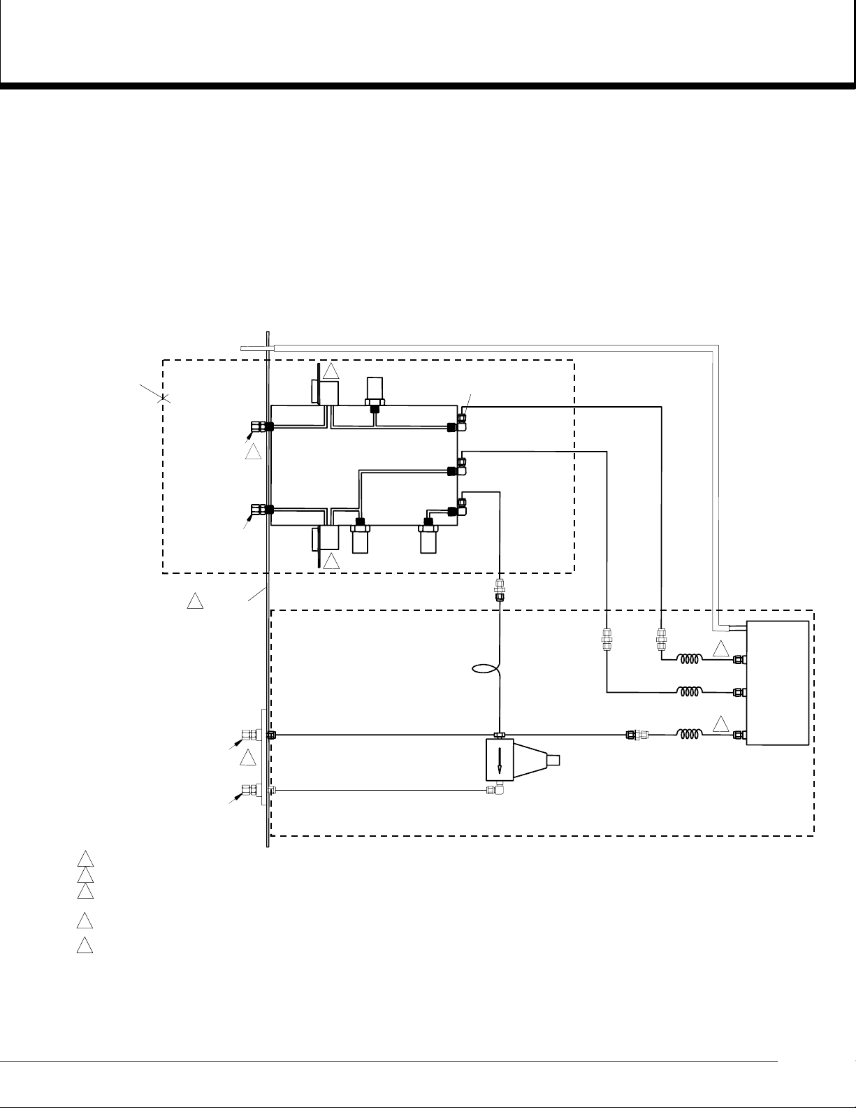
FID EXHAUST
2
FUEL FLOW
CONTROL
FLUISTER
VALVE
659541
4
MANIFOLD
SENSOR, FUEL
PRESSURE
0-30 PSIG
659498
FTG, ELBOW
1/16T-1/8MPT
904582
(3)
659072
659038
659037
FLOW CONTROL
MANIFOLD ASSEMBLY
659043
FUEL IN
FTG, BULKHEAD
W/RESTRICTOR
1/4T-1/8MPT
1
AIR IN
FTG, MALE CONN
1/4T-1/8MPT
008435
W/FILTER 017154
REAR PANEL5
SAMPLE IN
FTG, BULKHEAD
SAMPLE OUT
FTG, MALE CONN
1/4T-1/8MPT
008435
5 REAR PANEL IS INCLUDED IN F LOW CONTROL MANIFOLD ASSEMBLY 659043.
4 MANIFOLD ASSEMBLY 659043 MUST BE RETURNED TO FACTORY WHEN REPLACMENT OF AIR AND/OR FUEL FLOW FLUISTER VALVES IS REQUIRED.
3 15 PSI 2 L/MIN.: 659178
2 PSI 1 L/MIN.: 659073
NO RESTRICTOR: 0084 35
2 STD MIXED FUEL: 659514
1 STD MIXED FUEL: 658146 FUEL CAPILLARY, 659031 SAMPLE CAPILLARY
AIR FLOW
CONTROL
FLUISTER
VALVE
659541
4
SENSOR, AIR
PRESSURE
0-30 PSIG
659498
3
SENSOR, SAMPLE
PRESSURE
0-15 PSIG
659497
BACK PRESSURE
REGULATOR
659063
FTG, UNION
1/16T
818270
FTG ASSEMBLY
659173
FTG, FLBOW
1/4T-1/4MPT
902147
FTG, UNION
1/16T
818270
FTG, UNION
1/16T
818270
FTG, UNION
1/16T
818270
FUEL
CAPILLARY
AIR
CAPILLARY
SAMPLE
CAPILLARY11
FLAME
IONIZA TION
DETECTOR
(FID)
F
IGURE
748412-C
October 2000
1-3. FID2 A
NALYZER FLOW DIAGRAM
Flame Ionization Detector 2 Analyzer Module
Rosemount Analytical NGA 2000
3
1
INTRODUCTION
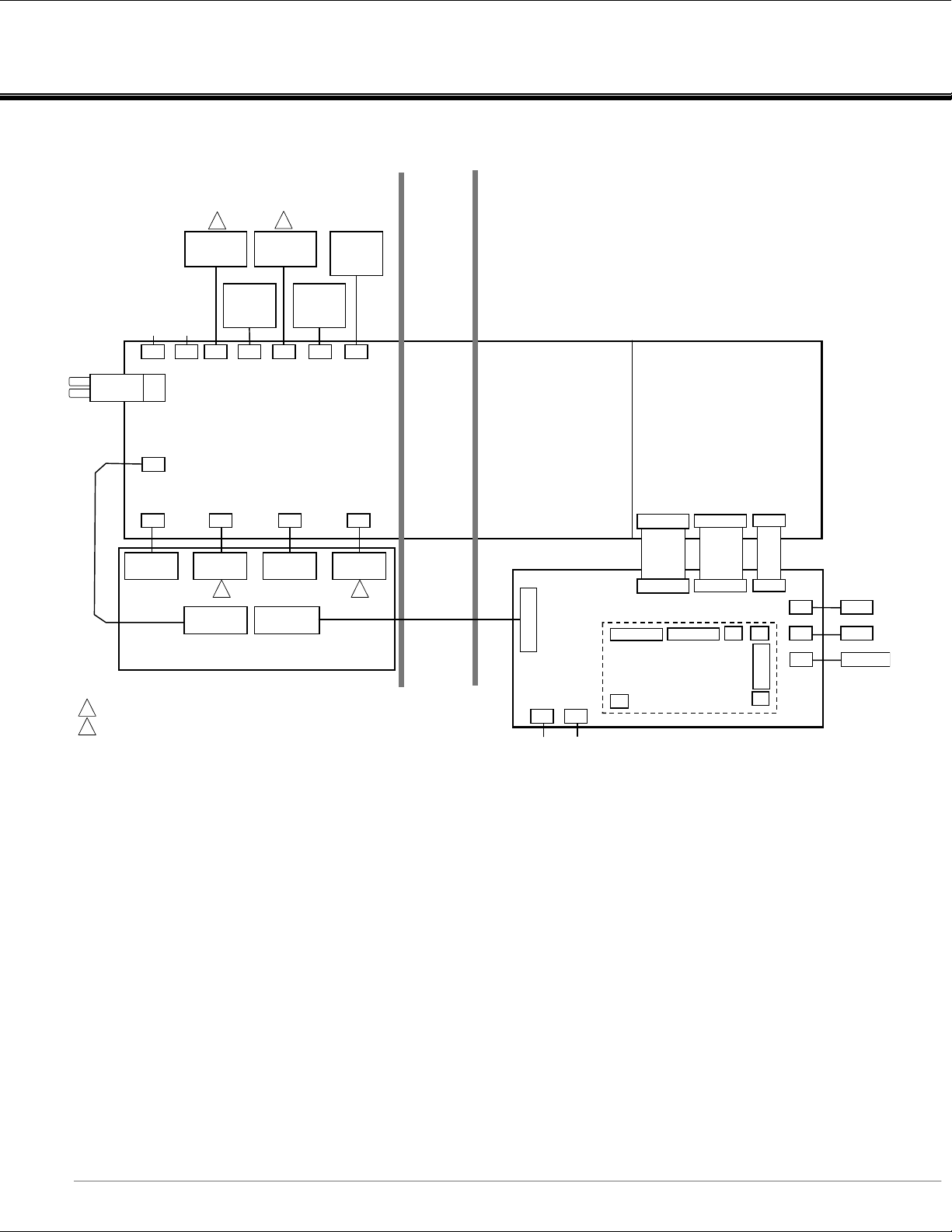
REAR SECTION OF ANALYZER FRONT SECTION OF ANALYZER
FLOW CONTROL
FLUISTOR
AIR
659070
THERMISTOR
BURNER
BLOCK HEATER
2
FUEL
J1
FLAME
FUEL
PRESSURE
SENSOR
0-30 PSIG
J12 J13J3 J11 J4
SAMPLE
RESSURE
SENSOR
0-15 PSIG
J6
POLARIZED
COLLECTOR
1
CABLE
CONTINUITY
FLOW CONTROL
NCNC
J7J2
J9
J16
J8 J5
IGNITER
BURNER BLOCK
2
AIR
FLUISTOR
PRESSURE
SENSOR
0-30 PSIG
INTRINSICALLY SAFE BOARD
POLARIZED
COLLECTOR
1
RTD
BURNER BLOCK ASSEMBLY
1
CONNECTORS J5 AND J6 ON INTRINSICALLY SAFE BOARD ARE INTERCHANGEABLE.
FACTORY REPLACEMENT.
2
MIDDLE
SECTION OF
ANALYZER
THIS SECTION OF INTRINSICALLY
SAFE BOARD CONTAINS CURRENT-
LIMITING RESISTORS
J15
J8J11
NCNC
THIS SECTION OF
INTRI N S I CALLY SAF E BO ARD
CONTAINS ±15 SUPPLIES,
+90V SUPPLY AND LOW-
LEVEL ANALOG CIRCUITS
J15
J15 J14 J25
MODULE BOARD 659060
J6 J5
COMPUTER BOARD
658350
J7
J14 J17
J1J4
J2
J3
J22
J24
J22
LON1
LON2
24V POWER
F
IGURE
Flame Ionization Detector 2 Analyzer Module
4
Rosemount Analytical NGA 2000
1-4. FID2 W
IRING DIAGRAM
748412-C
October 2000
INTRODUCTION
1.4 GAS SAFETY FEATURES
The FID2 module is divided into two parts - a pneumatic section and an electronic section.
The two sections are separated by a pair of solid partitions to prevent any leak of gas in the
pneumatic section from reaching the electronics. The electrical connections into the
pneumatic section are made intrinsically safe by a series of over-voltage protection devices
and current limiting resistors. The burner itself is an explosion-proof assembly. The
combination of these two techniques allows the analyzer to meet international safety
standards without the use of an expensive continuous-dilution purge - but ONLY when it is
installed in a general purpose area with good air circulation.
WARNING: POSSIBLE EXPLOSION HAZARD
Hydrocarbon concentration(s) in the sample gas must be below the Lower
Explosion Limit (LEL).
1
All tubing ahead of the burner is rigid metallic tubing assembled with ferrule/nut type
compression fittings. However, should an internal fuel leak occur, a worst-case leak would
be dissipated below 25% of the LEL of hydrogen by natural dilution outside of the pneumatic
section before it could be ignited by any external ignition source, and there is nothing within
the pneumatic section to ignite it.
The FID2 is designed to use 40% H2/60% He fuel at a maximum inlet pressure of 3446 hPagauge (50 psig).
1
WARNING: POSSIBLE EXPLOSION HAZARD
Protection against explosion depends upon a special fuel flow restrictor at the
fuel inlet. DO NOT REMOVE THE FUEL INLET RESTRICTOR.
1.5 FUEL GAS OPTION
The standard FID2 Analyzer Module requires 40% hydrogen/60% helium burner fuel gas.
For monitoring internal combustion exhaust emissions or other sample gas with varying
oxygen content, mixed fuel is preferable. In fact, a hydrogen/helium mixture is more
desirable than a hydrogen/nitrogen mixture. With this type of sample, the use of mixed fuel
gas minimizes the error introduced by oxygen synergism.
1
The fuel restrictor is part of the Flow Control Manifold Assembly, which is specific to an application.
748412-C
October 2000
Flame Ionization Detector 2 Analyzer Module
Rosemount Analytical NGA 2000
5

1
INTRODUCTION
Changes in the burner air flow rate have little effect on signal strength. For a given flow, the
signal can be optimized by adjusting the fuel flow rate.
Typical flow rates to the burner:
GAS FLOW MIXED FUEL
F
UEL
S
AMPLE
A
IR
T
ABLE
1-1. G
AS FLOW RATES
100 cc/min
10 cc/min
400 cc/min
ANALYZER CHARACTERISTICS 40% H2/60% He
F
ULL SCALE SENSITIVITY
F
UEL CONSUMPTION
O
PERATING SETTING FOR SAMPLE PRESSURE REGULATOR
T
ABLE
1-2. A
NALYZER CHARACTERISTICS RELATIVE TO FUEL GAS
4 ppm, CH4 to <1%, CH
100 to 110 cc/min
345 hPa-gauge (5 psig)
4
Flame Ionization Detector 2 Analyzer Module
6
Rosemount Analytical NGA 2000
748412-C
October 2000

INSTALLATION
2.1 UNPACKING
When the FID2 Analyzer Module is received, carefully examine the shipping carton and
contents for signs of damage. Immediately notify the shipping carrier if the carton or
contents is damaged. Retain the carton and packing material until all components
associated with the Analyzer Module are operational.
2.2 ASSEMBLY
The FID2 analyzer module MUST NOT be placed within a conventional NGA platform,
single module enclosure or dual module enclosure since the latter would not allow free flow
of air around the module, thus violating its safety certification. The enclosure is designed so
that this would be very hard to do anyway.
2
There is a special platform specifically designed to accept this module; consult the factory
for details.
Install the Platform and I/O Module(s) according to guidelines in the Platform manual.
2.3 LOCATION
WARNING: POSSIBLE EXPLOSION HAZARD
Do not place the FID2 module within another enclosure unless the latter has a
guaranteed air circulation such as to dilute a worst case fuel or sample leak
below 25% of the LEL. Failure to will negate the safety features and may result
in explosion, serious injury, material damage and death. Also, do not cover the
vent holes on the top and sides of the module.
Install the Analyzer Module in a clean, weather-proofed, non-hazardous, vibration-free
location free from extreme temperature variations. For best results, install the Analyzer
Module near the sample stream to minimize sample transport time.
Operating ambient temperature is 5 °C to 40 °C, limited to temperature changes of less than
10 °C/hr. Acceptable dew point range is less than 95% relative humidity, but not in excess
of 40°C wet bulb temperature.
748412-C
October 2000
Flame Ionization Detector 2 Analyzer Module
Rosemount Analytical NGA 2000
7

2
INSTALLATION
The cylinders of fuel, air, and calibration gases should be located in an area of relatively
constant ambient temperature .
2.4 G
During normal operation, the Analyzer Module requires fuel and air to maintain the burner
flame as well as suitable standard gases for. Refer to the criteria for selection of these
gases in Section 2.4.2.
After initial startup or after startup following a prolonged shutdown, the analyzer may display
baseline drift for a considerable period of time, particularly on the most sensitive range.
Commonly, the drift is caused by small amounts of organics (such as hydrocarbons) in the
inner walls of the tubing in both the internal flow system and the external gas supply system.
Drift results from any factor influencing the equilibrium of these adsorbed hydrocarbons,
such as temperature or pressure. Hydrocarbons adsorbed within the analyzer in the gas
passageways (or in the fuel or air lin es) will elevate the overall baseline.
Note that this type of drift occurs only when the flame is burning. If drift occurs when the
flame is extinguished, the electronic circuitry is at fault or the burner or cabling is
contaminated with a conductive film. To minimize drift, use clean fuel and air, keep the
analyzer clean, and locate the gas cylinders in an area of relatively constant ambient
temperature.
The cylinders supplying all gases each should be equipped with a clean, hydrocarbon-free,
two-stage regulator and a shutoff valve.
ASES
All new external gas tubing (except for SAMPLE BYPASS) is strongly recommended,
preferably pre-cleaned, stainless steel, gas chromatograph-grade tubing. Thoroughly clean
before use (if a hydrocarbon-based cleaning solvent such as acetone is used, purge tubing
with dry nitrogen or helium for several minutes before using.)
Gas line connections are compression fittings. Do not use pipe thread tape on such fittings.
Since the oxidation of hydrogen is accompanied by the formation of water vapor, the
exhaust tubing always should be slanted downward at least 6 degrees from horizontal.
Otherwise, water may accumulate in the line, causing back pressure and noisy readings, or
may back up in the line and flood the burner.
If the sample is toxic or noxious, or is to be reclaimed, connect the Bypass outlet to a
suitable disposal system. Do not use any device that may cause back pressure in the line.
Flame Ionization Detector 2 Analyzer Module
8
Rosemount Analytical NGA 2000
748412-C
October 2000
 Loading...