

Rosemount Manual: NGA 2000 CLD NO/NOx Analyzer Module SW 3.9-3rd Ed. | Rosemount Manuals & Guides
Instruction Manual
HAS60E-IM-SW39
10/2005
Software Version 3.9.x
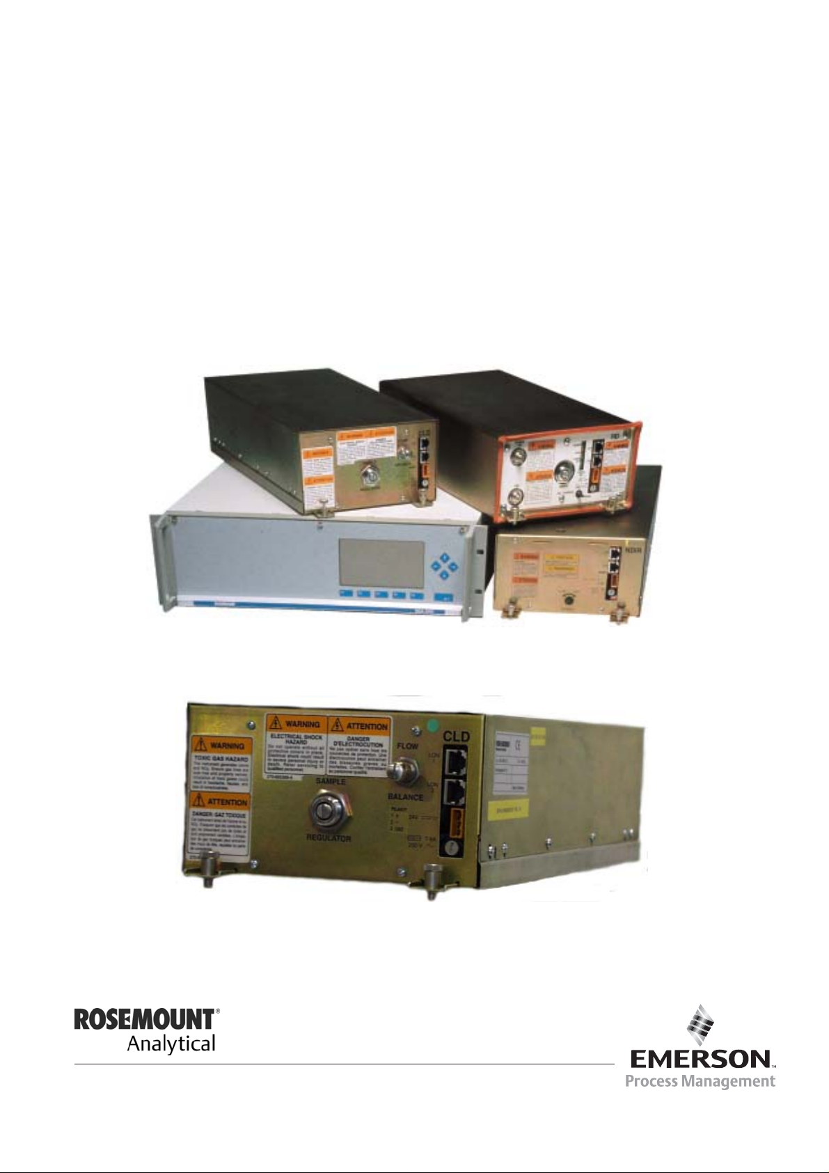
NGA 2000 Software Manual for
CLD Analyzer Module (combined with
NGA 2000 Plat form, MLT, CAT 200 or TFID Analyzer)
www.EmersonProcess.com

CLD Software 3.9.x Instruction Manual
HAS60E-IM-SW39
10/2005
ESSENTIAL INSTRUCTIONS
READ THIS P AGE BEFORE PROCEEDING!
Emerson Process Management (Rosemount Analytical) designs, manufactures and test s
its products to meet many national and international standards. Because these instruments
are sophisticated technical products, you MUST properly install, use, and maintain
them to ensure they continue to operate within their normal specifications. The following
instructions MUST be adhered to and integrated into your safety program when installing,
using and maintaining Emerson Process Management (Rosemount Analytical) products.
Failure to follow the proper instructions may cause any one of the following situations to
occur: Loss of life; personal injury; property damage; damage to this instrument; and warranty
invalidation.
• Read all instructions prior to installing, operating, and servicing the product.
• If you do not understand any of the instructions, contact your Emerson Process
Management (Rosemount Analytical) representative for clarification.
• Follow all warnings, cautions, and instructions marked on and supplied with the product.
• Inform and educate your personnel in the proper installation, operation, and
maintenance of the product.
• Install your equipment as specified in the Installation Instructions of the appropriate
Instruction Manual and per applicable local and national codes. Connect all products
to the proper electrical and pressure sources.
• T o ensure proper performance, use qualified personnel to install, operate, update, program,
and maintain the product.
• When replacement parts are required, ensure that qualified people use replacement parts
specified by Emerson Process Management (Rosemount Analytical). Unauthorized parts
and procedures can affect the product’s performance, place the safe operation of your
process at risk, and VOID YOUR W ARRANTY. Look-alike substitutions may result in fire,
electrical hazards, or improper operation.
• Ensure that all equipment doors are closed and protective covers are in place, except
when maintenance is being performed by qualified persons, to prevent electrical
shock and personal injury.
The information contained in this document is subject to change without notice. Misprints
reserved.
st
1
Edition 05/2005 2nd Edition 07/2005
3rd Edition 10/2005
© 2005 by Emerson Process Management
Emerson Process Management
GmbH & Co. OHG
Industriestrasse 1
D-63594 Hasselroth
Germany
T +49 (0) 6055 884-0
F +49 (0) 6055 884-209
Internet: www.EmersonProcess.com

Contents
1 Introduction 1 - 1
2 Menu Structure 2 - 1
3 Startup and Operation, General Notes and Main Menu 3 - 1
3.1 Starting and Initializing....................................................................................3 - 1
3.2 Display and Function ......................................................................................3 - 2
3.3 "TAG" and Operating Keys .............................................................................3 - 2
3.4 Lines and Softkey Functionality ......................................................................3 - 3
3.5 Important Functions of the Soft keys...............................................................3 - 4
3.6 Entering/Changing Variables ..........................................................................3 - 5
3.7 The STATUS key ............................................................................................3 - 6
3.8 Main Menu ......................................................................................................3 - 7
4 Analyzer Basic Controls (Calibration) & Setup 4 - 1
4.1 Analyzer Channel Status: Current Measurement Parameters ........................4 - 3
4.1.1 Multi Component Display: Change of Channel ...............................................4 - 5
4.1.2 Multi Component Display: Sequence setup ....................................................4 - 7
4.1.3 Range Setting .................................................................................................4 - 9
4.1.4 Automatic Range Control................................................................................4 -13
4.1.5 Enable/Disable Ozonator Power .....................................................................4 - 17
4.1.6 Measurement Mode: NO↔NOx.......................................................................4 - 21
4.2 Calibration.......................................................................................................4 - 23
4.2.1 Zeroing (Zero Calibration)...............................................................................4 - 23
4.2.2 Spanning (Span Calibration) ...........................................................................4 - 27
5 Analyzer and I/O, Expert Controls & Setup 5 - 1
5.1 Analyzer Module Setup…………………………………………………………….5 - 3
5.1.1 Calibration/Calibration gas list.........................................................................5 - 5
5.1.2 Calibration parameters....................................................................................5 - 11
5.1.3 Concentration alarm setup..............................................................................5 - 13
5.1.4 Gas measurement parameters .......................................................................5 -15
5.1.4.1 Linearization parameters ................................................................................5 - 17
5.1.4.2 Response time/delay parameters ...................................................................5 - 19
5.1.4.3 Range setting..................................................................................................5 - 21
5.1.4.4 Automatic range control ..................................................................................5 - 23
I
HAS60E-IM-SW39(3) [CLD Software 3.9.X)] 10/05
NGA 2000

5.1.4.5 Units ............................................................................................................... 5 -25
5.1.4.6 Linearization functions.................................................................................... 5 - 27
5.1.5 Analyzer parameter list................................................................................... 5 - 33
5.1.6 Physical measurement parameters ................................................................ 5 - 33
5.1.7 Displayed parameters .................................................................................... 5 - 39
5.2 I/O Module Controls .......................................................................................5 - 41
5.2.1 System SIO Module ....................................................................................... 5 - 43
5.2.1.1 Analog output setup ....................................................................................... 5 - 45
5.2.1.2 Serial interface setup...................................................................................... 5 - 51
5.2.1.3 Relay outputs settings .................................................................................... 5 - 53
5.2.2 System DIO Module(s).................................................................................... 5 - 57
– Configuring the DIO module inputs........................................….......... 5 - 59
– Configuring the 24 DIO module outputs.....................................…...... 5 - 61
5.3 Analyzer Module Controls ..............................................................................5 - 63
6 System Configuration and Diagnostics 6 - 1
6.1 Diagnostic Menus........................................................................................... 6 - 3
6.1.1 Control Module Diagnostics............................................................................ 6 - 4
6.1.2 Analyzer Module Diagnostics ......................................................................... 6 - 5
6.2 Load/Save Configuration (CM/MCA) .............................................................. 6 - 7
6.3 Date and Time................................................................................................ 6 - 9
6.4 Security Codes ............................................................................................... 6 - 11
6.5 Measurement Display Setup ..........................................................................6 - 13
6.6 Miscellaneous................................................................................................. 6 - 15
7 Display Controls 7 - 1
Supplement:
Calculator on Control Module Level (CM Calculator) Page 1 - 14
Programmable Logic Control on Control Module Level (CM PLC) Page1 - 28
System Calibration Page1 - 34
NGA 2000
HAS60E-IM-SW39(3) [CLD Software 3.9.X)] 10/05
II

1 Introduction
This software manual describes step by step how to operate successfully the Emerson
Process Management NGA 2000 Series CLD analyzer modules and analyzers (Analyzer
Module in a platform).
Chapter 2 shows the structure of the CLD software menus. Chapter 3 describes the
display and the keyboard of the analyzer and the main menu and submenus. Chapter 4
describes the basic controls incl. measurement and calibration with detailed
illustrations. So you can easily compare the actual analyzer (module) display with the
illustrations of the manual.
Chapter 5 describes the expert configurations of the analyzer module and of the Input/
Output modules (I/O modules). Chapter 6 describes the system configuration and
diagnostics. The layout of both chapters is not as detailed. In chapter 7 you will find some
information about the display controls.
Some co nte nt s o f t he e xpe rt co nf igu ra ti ons are not important for each customer. It depends
on the configuration of your NGA 2000 system, relative to the following components:
♦ Control Module CM
♦ Analyzer Module AM
♦ Input/Output Modules I/O's (SIO = Standard I/O, DIO = Digital I/O)
♦ Network I/O Modules Analog I/O with 3 Alarms, Autocalibration I/O, System
Autocalibration I/O
You can distinguish the following system units and SIO/DIO configurations:
System Unit SIO/DIO Configuration
CLD analyzer module (AM):
• without front panel,
i.e. without control unit
• can be combined with a platform,
a MLT/ CAT 200/ TFID analyzer or
a customer developed control unit
⇒ 1 local SIO and 1 local DIO (or 2
local DIO’s) can be installed in the
MLT/TFID analyzer module only
⇒ SIO and DIO can be configured
for the MLT AM channels or the
TFID analyzer module only
⇒ => No local CLD I/O’s
Section
∗ See
MLT/TFID
Instruction
Manual
Platform (CM Software):
• Control unit with front panel
• Without measurement channels
⇒ 1 SIO and up to 4 DIO's can be
installed in the platform (CM I/O’s)
⇒ SIO and DIO can be configured
∗ 5.2
for all AM channels combined with
the platform, e.g. for the CLD
=> System I/O’s
CLD analyzer (CM plus CLD
Analyzer Module Software):
• CLD Analyzer: CLD AM in a
platform with front panel
• CLD AM combined with MLT/TFID
or CAT 200 analyzer,
i.e. all functions of the control unit
and of the CLD Analyzer Module
are shown
HAS60E-IM-SW39 (2) [CLD Software 3.9.X] 07/05
⇒ 1 SIO and 1 DIO (or 2 DIO’s) can
be installed in the MLT/ CAT 200/
TFID analyzer (CM I/O’s)
⇒ SIO and DIO can be configured
for all AM’s
combined with the MLT/
CAT 200/ TFID analyzer, e.g. CLD
=> System I/O’s
NGA 2000
∗ 5.2
1 - 1

The following illustrations shall clarify the relationship between the hardware configuration
A
A
and the software setup of the modules:
NGA 2000 System via Platform and CLD Analyzer Module
(separate
Manual)
(separate
Manual)
Local
I/O's
SIO
nalyzer
Modules (AM's)
TFID
DIO
SIO
MLT
DIO
CLD
(additional
manuals)
(additional
manuals)
HFID
FID
Control
Module (CM)
Platform
System I/O
Modules
1 SIO
4 DIO's
max.
Network
I/O’s
(see 5.2.1)
(see 5.2.2)
(see 5.2.3)
NGA 2000 System via MLT/ CAT 200 Analyzer and CLD Analyzer Module
(separate
Manual)
(separate
Manual)
Local
I/O's
SIO
nalyzer
Modules (AM's)
MLT
DIO
SIO
TFID
DIO
Control
Module (CM)
System I/O
Modules
1 SIO
1 DIO
(separate
Manual)
(separate
Manual)
CLD
(additional
manuals)
(additional
manuals)
CAT 200
FID
MLT/ CAT 200 Analyzer
1 - 2
NGA 2000
HAS60E-IM-SW39 (2) [CLD Software 3.9.X] 07/05

1 Introduction
A
NGA 2000 System via TFID Analyzer and CLD Analyzer Module
(separate
Manual)
(separate
Manual)
Local
I/O's
SIO
nalyzer
Modules (AM's)
TFID
DIO
SIO
MLT
DIO
Control
Module (CM)
System I/O
Modules
1 SIO
1 DIO
(separate
Manual)
(separate
Manual)
CLD
(additional
CAT 200
TFID Analyzer
manuals)
(additional
manuals)
FID
Chapter 5 & 6:
The layout of both chapters is not as detailed as in chapter four:
Normally, the way to a certain menu of the CLD software is described
catchwords
you have to press to reach this menu. You will find the illustration of the
with the software
corresponding LCD screen at the end of the catchword listing. After that you can read the
meaning of the functions and variables of each expert or system configuration menu.
Note:
This software manual will describe the software of all CLD analyzer modules combined
with a platform, an MLT analyzer or a TFID analyzer. This includes also CAT 200
which is
a MLT 1 in an Ex d enclosure with a magnetically operated front panel. For CAT 200 an
addendum instruction manual
is offered for CAT specific issues.
CLD Analyzer Modules being operated with a customers control unit will not be described
in this manual.
For Network I/O Modules
separate manuals are available being used for detailed
information. This CLD software manual describes the Network I/O specific functions as
short form only.
Please consult our Service Support Center for more information!
HAS60E-IM-SW39 (2) [CLD Software 3.9.X] 07/05
NGA 2000
1 - 3

1 - 4
NGA 2000
HAS60E-IM-SW39 (2) [CLD Software 3.9.X] 07/05

2 Menu structure
HAS6OE-IM-SW39(1) [NGA-e (CLD-Software 3.9.x)] 04/04
NGA 2000
2 - 1

2 - 2
NGA 2000
HAS6OE-IM-SW39(1) [NGA-e (CLD-Software 3.9.x)] 04/04
3 Startup and Operation, General Notes and Main Menu
3.1 Starting and Initializing
After switching on the CLD analyzer or analyzer module (in a platform or part of a NGA network), the
initialization procedure will be performed. A self control of the analyzer modules or the analyzer is
running. You can see a sequence of several displays. They show the status of initialization, revision
notes of the CLD software and the Emerson tag:
(C) 2004 EMERSON Process Management
NGA 2000 Control-Module Rev. 3.7.1 /P008
LCDReset Abort
F1
Language: P014/01/00
Initializing Network
Initializing network interface
F2
F3 F4
F5
After “Initializing network interface” the next display shows “Searching for nodes” followed by “Querying
module 1: CLD, x % complete”, “Searching for nodes” and “Calculating binds”.
If you press the F1 -key during the initializing, you will reset the LCD brightness and contrast to factory
settings (see also section 7). Pressing the F3 -key will abort the network initializing. Then you will have
no connection to any analyzer module. Only the menus of the control module (platform, MLT or TFID
analyzer) will be available.
At the end of the initializing procedure you can see the single component display of the CLD
analyzer module (see illustration on next page). It is the
origin to all the other channels, menus and
submenus.
The instructions of the basic controls (chapter four) all begin with the single component display. The
actual display might differ from the shown one because the customer can configure it according to his
requirements.
HAS6OE-IM-SW39(1) [NGA-e (CLD-Software 3.7.x)] 04/04
NGA 2000
3 - 1
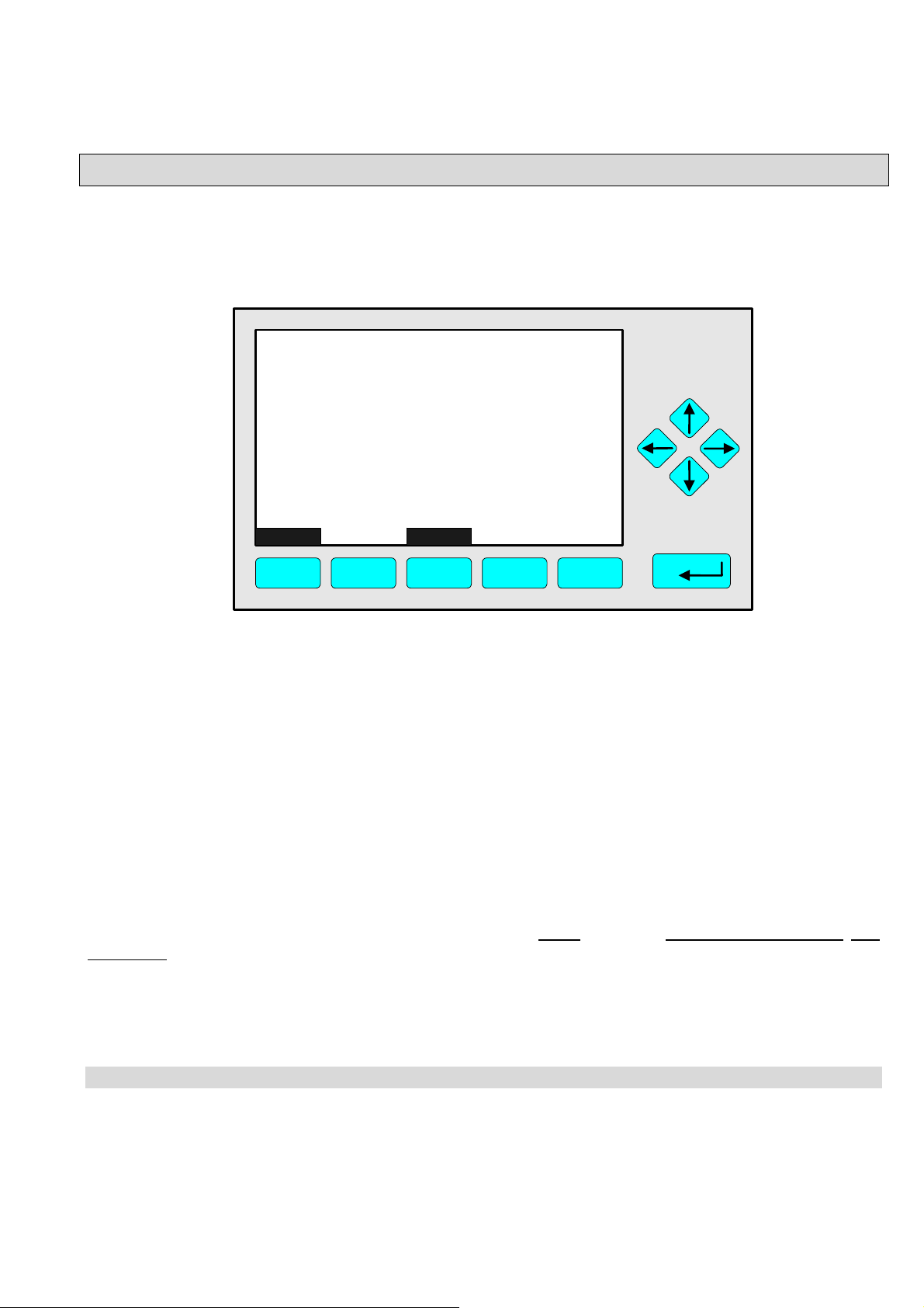
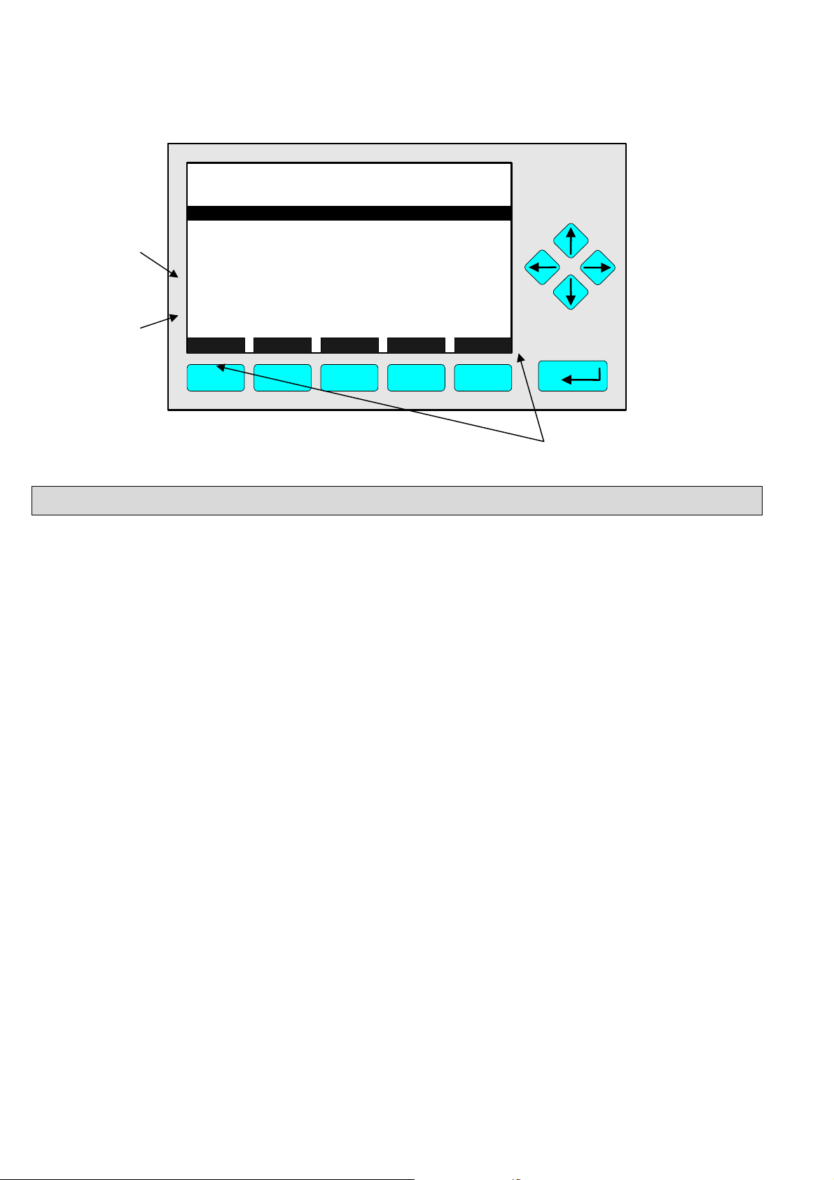
3.2 Display and Function
The LCD-screen shows all measurement values of the analyzer and all customer instruc-tions. You can
operate with five function keys, four arrow keys (cursors) and the enter key. The function of each key
depends on:
♦
the type of analyzer/analyzer module used
♦ the optional auxiliary modules (e.g. I/O boards) used
♦ the individual menu displayed
In case of power failure all customer specific module parameters are saved by a batterypowered buffer.
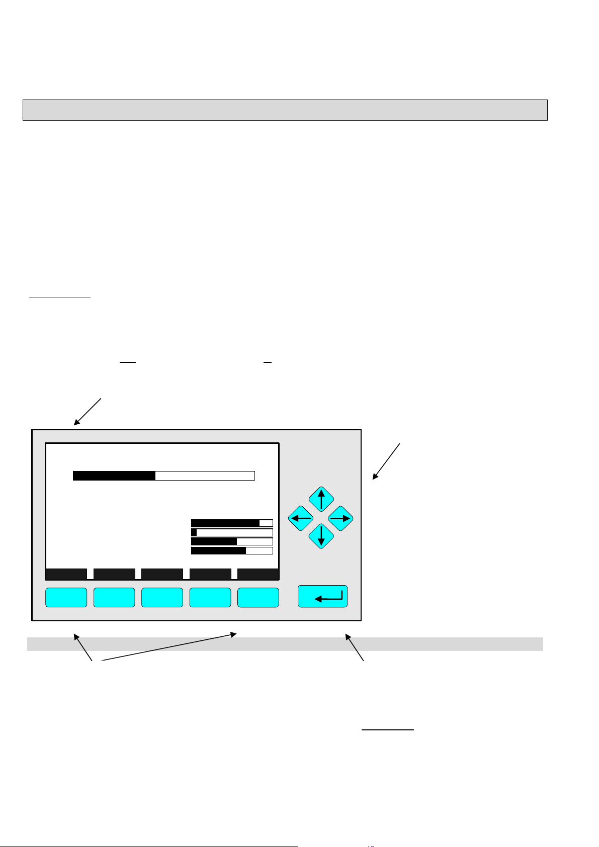
At the top left of each menu page you will find the tag of the current channel.
Typical tags:
♦ CLD-R1: CLD Analyzer or Analyzer Module, Range 1.
In this manual you will find normally "TAG" as general name. But in the specific CLD menu pages you
will find "CLD".
♦ CH1/NH3/R1: /
CHannel 1 / Gas: Ammonia / Range 1
System tag (factory setting: here, WO stands for "Work Order"
CLD_WO935077
95.0 ppm
95.00 ppm NOx
50
-1.5
45
150
F.S.
490
1.5
55
500
F5
0 Range: 4 250
Sample press.:
Detector temp.:
Block temp.:
Converter temp.:
Display... Status... Main... Channel BasicCal
F1
F2
340 hPa
0.5 C
51.5 C
360 C
F3 F4
Cursor keys:
↑ -key / ↓ -key:
♦ Line up / line down
within the same menu
♦ Alteration of numbers,
variables or digits
← -key/ → -key:
♦ Moving back/forwards
between the pages of
a menu
♦ Selection of digits
Function Keys:
♦ Keys without defined functions
♦ The current function depends on the
menu selected
♦ The softkey legend is shown on the
display above the key
3 - 2
NGA 2000
Enter Key:
♦ To confirm a previously entered
value (variable)
♦ To start a selected function
(
Alternative: → -key)
♦ To go into a menu (via menu line)
HAS6OE-IM-SW39(1) [NGA-e (CLD-Software 3.7.x)] 04/04
3 Startup and Operation, General Notes and Main Menu
y
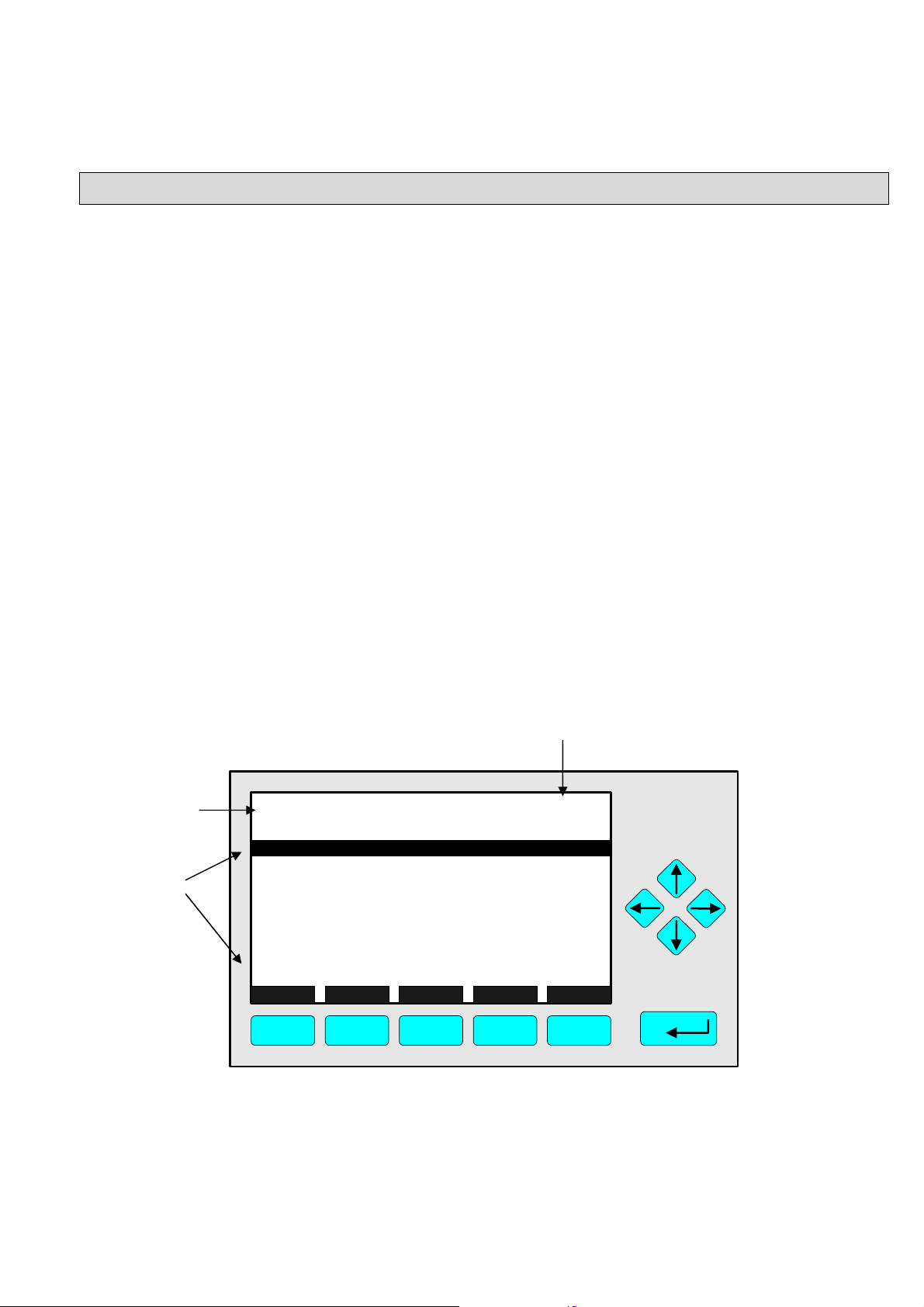
3.4 Lines and Softkey Functionality
Lines can be selected by the ↓ -key or the ↑ -key. The selected line is displayed white on black. You
have four different types of lines in the menu:
Menu line...
♦ Line ending with three dots.
♦ You will go to a submenu by pressing the ENTER key or the → -key in such a line.
Function line !
♦ Line ending with an exclamation-mark.
♦ You will start a function (e.g. NO/NO
the → -key in such a line.
Line of variables:
♦ Line ending with a colon.
♦ Display of module parameters (variables).
♦ Some parameters can be changed (e.g. range number), some parameters display only a
status (e.g. calibration status) and cannot be changed.
Text line
♦ Line without any punctuation marks.
♦ Only display of informations (e.g. analyzer module tag).
Signal of the current channel (see TAG).
Is always displayed on the single component
-toggle) by pressing the ENTER key or
x
displa
.
Text line
Lines of
variables
TAG
Basic Controls
Measurement range number:
Range upper limit:
Automatic range change control:
Ranges with valid calibration:
Calibration status:
Span gas concentration:
Status:
Measurement mode:
Ozonator status:
Ozonator power:
HOME NO/NOx ZERO SPAN INFO
F1
F2
F3 F4
95.0 ppm
250.0 ppm
Disabled
1&2&3&4
READY
0.0 ppm
STANDBY
NOx mode
Enabled
F5
4
ON
HAS6OE-IM-SW39(1) [NGA-e (CLD-Software 3.7.x)] 04/04
NGA 2000
3 - 3
Function
line
Menu
line
TAG
Zero/span calibration
Measurement range number:
Zero gas concentration:
Span gas concentration:
Sample flo
Raw
Measur
NO/NOx toggle!
Status:
Result...
Calibrati
HOME FACTORS ZERO SPAN INFO
F1
w:
measurement signal:
ement gas:
on adjustment limits:
F2
F3 F4
95.0 ppm
1
0.0 ppm
100.0 ppm
1100 ml/min
528218.1
NO mode
READY
Disabled
F5
Function key legend
3.5 Important Functions of the Softkeys
DISPLAY
♦ Change from the single component display to the multi component display.
MEASURE
♦ Change from the main menu to the single component display.
STATUS (see 3.7)
♦ Change to the “Analyzer Channel Status" : Display of the most important parameters and
status informations of the CLD module or of the current channel.
♦ If available, this command is always assigned to the F2 -key.
MAIN
♦ Change from the single component display to the main menu.
CHANNEL
♦ Change of the channel in the same menu. This will only be possible, if several channels of an
analyzer or of combined analyzers are existing. Then, all available channels can be selected
one after another.
♦ In the main menu you can move among all channels of the connected analyzers and
analyzer modules. In the submenus you can only move among the channels of the current
analyzer or analyzer module.
ESCAPE or <<<
♦ Changing back to the last menu page selected.
♦ Reset of a changed but not confirmed parameter to the former value resp. to zero.
BACK
♦ Moving back to the last menu page selected (Alternative: ← -key) or
reset of a changed but not confirmed parameter to the former value.
3 - 4
NGA 2000
HAS6OE-IM-SW39(1) [NGA-e (CLD-Software 3.7.x)] 04/04

3 Startup and Operation, General Notes and Main Menu
BasicCal
♦ Change from the single component display to the menu "Analyzer module calibration".
♦ F5 in the single component display.
LOCK
♦ Lock of any operation level, if activated. Each of the three operation levels has to be
activated separately.
♦ F4 in the main menu.
MFG Data (see section 8 pp. 8-1ff)
♦ Change from the main menu to the menu "Module Manufacturing Data":
Further submenus are available with information about the control module and analyzer
module data, such as address of the manufacturer, serial number of the modules or the
software and hardware revisions.
♦ F5 in the main menu.
Info
♦ Change from the single component display to the menu "Analyzer module calibration".
♦ F5 in the single component display.
More
♦ Changing to a further menu page.
3.6 Entering/Changing of Variables
ENTER Key
♦ If you will press this key in a line of variables, the parameter will be displayed white on black
and can be changed. After you will have set up a new value, you can confirm it by pressing
the ENTER key again.
↑ -key / ↓ -key
♦ Function will depend on the variable selected: - Changing of the parameter values
- Scrolling among variables selected
- Changing of digits or characters
♦ Increasing or decreasing of numbers.
← -key / → -key
♦ Selection of digits within a parameter.
♦ For some variables you can change the quantity of digits or characters.
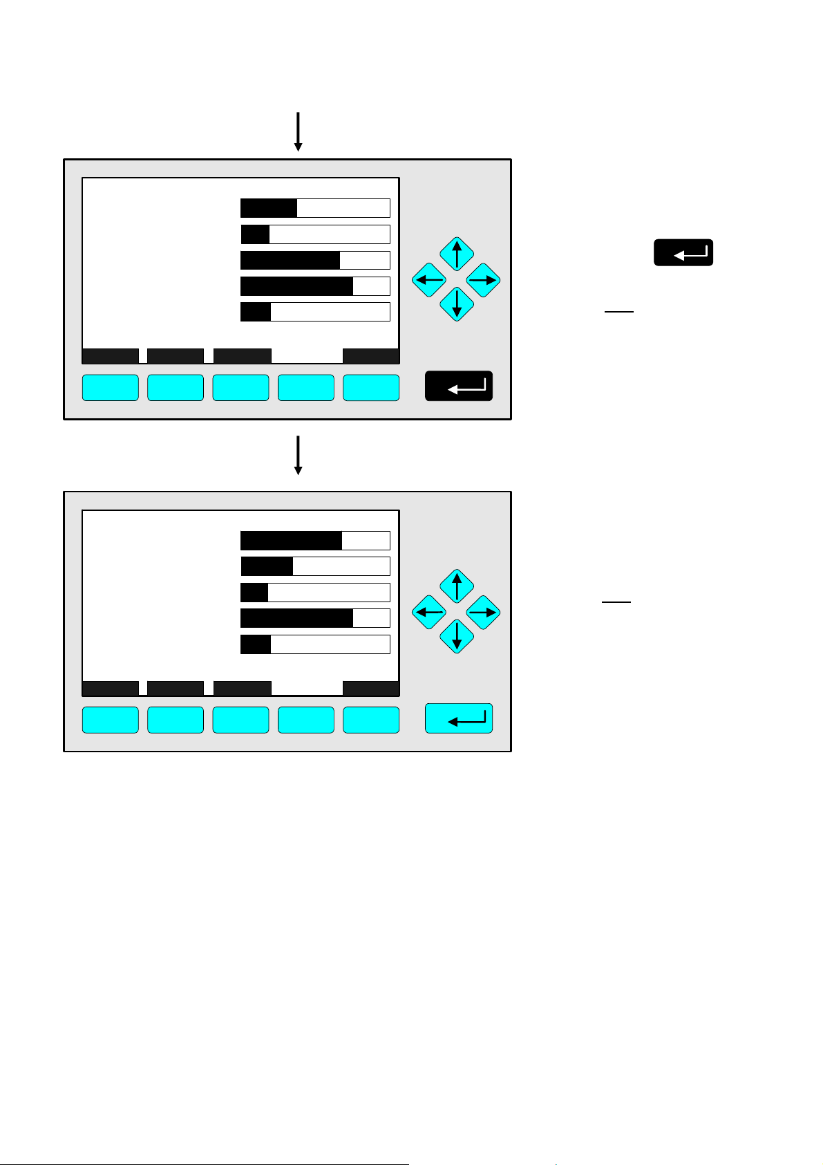
3.7 The STATUS Key
From the single component display or from the main menu you can change with the
F2 -key (STATUS) to the menu "Current measurement parameters" (illustration on next page):
HAS6OE-IM-SW39(1) [NGA-e (CLD-Software 3.7.x)] 04/04
NGA 2000
3 - 5

TAG
Current measurement parameters
Analyzer gas measured:
Measurement range number:
Range change control:
Linearization mode:
Analyzer operational state:
Analyzer alarm state:
Alarms reported:
Current total variable updates per second:
HOME ESCAPE MORE INFO
F1
F2
F3 F4
↓
TAG
Current measurement parameters
Response time:
Bypass flow:
Capilliary pressure:
Detector temperature:
95.0 ppm
NOx
3
Local
Disabled
STANDBY
NORMAL
FAILURE
24
F5
95.0 ppm
3.0 s
1100 ml/min
340 hPa
0.5 C
HOME ESCAPE MORE INFO
F1
F2
F3 F4
F5
In the menu "Current measurement parameters" you can control the status of the CLD analyzer
module. With the F3 -key (MORE) you can change to a further menu page of this menu. With
the F2 -key (ESCAPE) you can always go back to the main menu. From the second menu page
you can return to the first with the F4 -key (MORE) or the ← -key.
In the menu "Current measurement parameters" you will only find status information. You
cannot change the setups there. If you want to modify some parameters, you have to change to
the menu "Basic Controls" (see chapter 4) or to the menu "Analyzer module set up" (see
chapter 5.1) or "Analyzer module controls" (see chapter 5.3).
3.8 Main Menu
If you press the F3 -key (Main...) or the → -key in any single component display, you will change
to the "Main Menu". From there you can change to all operating levels of your CLD analyzer or
analyzer module to set up and control the parameters of measurement, calibration and data
transfer!
3 - 6
NGA 2000
HAS6OE-IM-SW39(1) [NGA-e (CLD-Software 3.7.x)] 04/04

3 Startup and Operation, General Notes and Main Menu
p
Via the F5 -key (MFG Data) you can change to several submenus, where you will find a lot of
important data about the control module (CLD analyzer or platform) and the analyzer module,
such as service address or serial number!
Options from the Main Menu:
TAG
-- Main Menu --
Analyzer basic controls (calibration) & setup...
Analyzer and I/O, expert controls & setup...
System configuration and diagnostics...
Display controls...
_____________________________________________
Time & Date:
System tag:
Measure Status... Channel Lock... MFG Data
F1
F2
F3 F4
14:03:25 May 02, 2005
F1
F2
F3
F4
Changing to the single component display of the
current channel
Changing to the menu "Current measurement
parameter" of the current channel
Scrolling through all channels of the connected
analyzers and analyzer modules
Lock of any operating level by security code
95.0 ppm
Emerson
F5
See chapter 4!
See chapter 5!
See chapter 6!
See chapter 7!
To setu
Factory Setting
Section 3.1 pp. 3-1/2!
Section 4.1 p. 4-3!
See channel tag!
Section 6.4 p. 6-31!
see 6.3 p. 6-29
F5
Changing to the menu "Module Manufacturing Data"
Section 8 pp. 8-1ff
HAS6OE-IM-SW39(1) [NGA-e (CLD-Software 3.7.x)] 04/04
NGA 2000
3 - 7

3 - 8
NGA 2000
HAS6OE-IM-SW39(1) [NGA-e (CLD-Software 3.7.x)] 04/04

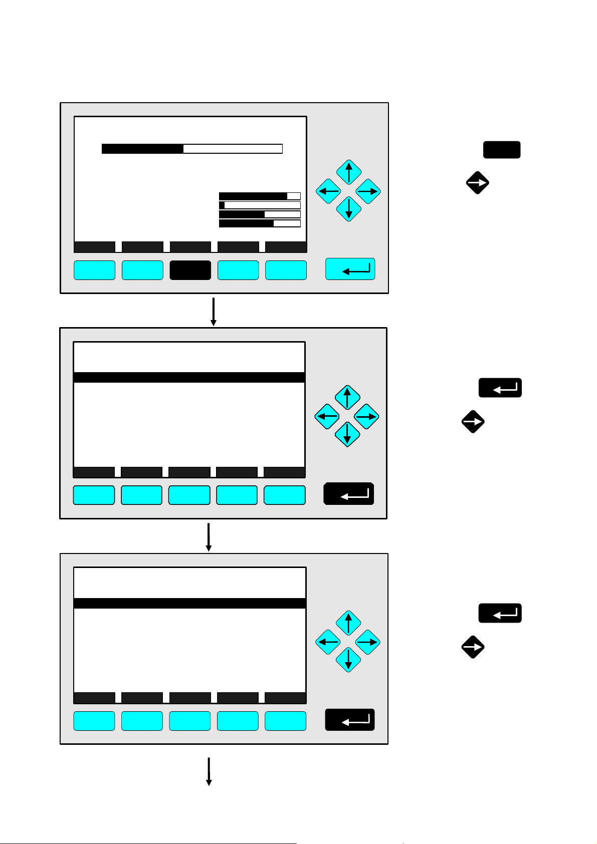
4 Analyzer Basic Controls (Calibration) & Setup
Basic Controls
In chapter 4 "Analyzer basic controls (calibration) & setup " you will find the most important
functions to set up your CLD analyzer module via an NGA front panel:
1) Measurement pp. 4 - 3ff (Chapters 4.1.1 and 4.1.2, pp. 4-5 to 4-8, are only important
for systems with several channels.)
2) Calibration pp. 4 - 23ff
All the necessary steps are explained with detailed illustrations and operation instructions. The
left column shows the display and keyboard of the NGA front panel. The keys you have to
press are illustrated in black. Instructions and notes are in the right-hand column. All the
instructions begin and end with a single component display, so you can compare the actual
display of the analyzer or analyzer module with the illustrations in this manual. Instructions are
completed, where needed, with notes and further information.
Example: You want to change from the single component display of NOx to the main menu
• Picture one shows the starting situation: single component display of NO
• If you press the F3 -key you will change to menu page shown in picture 2: Main Menu.
.
x
Left column: Right column:
LCD and keyboard Instructions and notes
CLD_WO935077
95.00 ppm NOx
0 Range: 4 250
Sample press.:
Detector temp.:
Block temp.:
Converter temp.:
Display... Status... Main... Channel BasicCal
F1
TAG
A naly zer basic cont r ols (calibration) & setup...
Analyzer and I/O, expert controls & setup...
Sy stem configuration and diagnostics.. .
Display controls.. .
Time & Date: 14:01: 4 5 29 July 19 99
System tag:
Measure Status... Channel Lock... MFG Data
F1 F2 F3 F4 F5
0.5 C
51.5 C
360 C
50
-1.5
F.S.
45
150
340 hPa
F2
Emerson
F3 F4
-- Main M enu --
95.0 ppm
490
1.5
500
F5
95.00 ppm
55
⇒ Change to the
“Main Menu”
Press
or
⇒ Next instruction
Press
or
F3
or step,
here e.g.:
Change to the
“Basic controls”:
HAS6OE-IM-SW39(1) [NGA-e (CLD-Software 3.7.x)] 04/04
NGA 2000
4 - 1

4 - 2
NGA 2000
HAS6OE-IM-SW39(1) [NGA-e (CLD-Software 3.7.x)] 04/04

4.1 Analyzer Channel Status
Current Measurement parameters
CLD_WO935077
95.00 ppm NOx
0.5 C
51.5 C
360 C
50
-1.5
45
150
F.S.
0 Range: 4 250
Sample press.:
Detector temp.:
Block temp.:
Converter temp.:
Display... Status... Main... Channel BasicCal
F1
F2
340 hPa
F3 F4
95.0 ppm
490
1.5
55
500
F5
⇒ Change to the
menu "Current
measurement
parameters"
Press
In the menu "Current
measurement parameters"
you will find the main
measurement parameters
These can be controlled in
the various set up menus.
F2
TAG
Current measurement parameters
Analyzer gas measured:
Measurement range number:
Range change control:
Linearization mode:
Analyzer operational state:
Analyzer alarm state:
Alarms reported:
Current total variable updates per second:
HOME
F1
ESCAPE
F2
MORE
F3
95.0 ppm
NOx
3
Local
Disabled
STANDBY
NORMAL
FAILURE
24
INFO
F4 F5
⇒ Change to the
“Main Menu”
F1
Press
Notes:
• Press the F3 key
(“MORE”) for further
information about the
current measurement
parameters.
• Pressing the F2 -key
(“ESCAPE”) will also
take you to the “Main
Menu”.
TAG
-- Main Menu --
Analyzer basic controls (calibration) & setup...
Analyzer and I/O, expert controls & setup...
System configuration and diagnostics...
Display controls...
_____________________________________________
Time & Date:
System tag:
Measure
Status...
04:03:25 May 02, 2005
Channel Lock MFG Data
F1 F2 F3 F4 F5
95.0 ppm
Emerson
⇒ Change to the
single component
display
Press
F1
HAS6OE-IM-SW39(1) [NGA-e (CLD-Software 3.7.x)] 04/04
NGA 2000
4 - 3

4 - 4
NGA 2000
HAS6OE-IM-SW39(1) [NGA-e (CLD-Software 3.7.x)] 04/04

4.1.1 Measurement - Multi Component Display:
Change of channel
F2
0.5 C
360 C
50
-1.5
45
150
F.S.
340 hPa
51.5 C
F3 F4
CLD_WO935077
95.00 ppm NOx
0 Range: 4 250
Sample press.:
Detector temp.:
Block temp.:
Converter temp.:
Display... Status... Main... Channel BasicCal
F1
95.00
45.00
333.0
150.0
20.00
Select Status... Tags Off
F1 F2 F3 F4 F5
MLT25/CH1/R2
MLT25/CH2/R2
MLT25/CH3/R2
MLT25/CH4/R2
CLD
ppm NOx
ppm CO
ppm SO2
ppm NO
%O2
0
0
0
0
0
[1]
[2]
[3]
[4]
[5]
95.00
>
45.00
333.0
150.0
20.00
Select Status... Tags Off
F1
MLT25/CH1/R2
MLT25/CH2/R2
MLT25/CH3/R2
MLT25/CH4/R2
F2 F3 F4 F5
CLD
ppm NOx
ppm CO
ppm SO2
ppm NO
%O2
0
0
0
0
0
[1]
[2]
[3]
[4]
[5]
95.0 ppm
490
1.5
55
500
F5
10
10
10
10
10
LCDReset
10
10
10
10
10
LCDReset
⇒ Change to the single
component display
of the channel
selected
Press
F1
⇒ Enable the selecting:
">"
Press
F1
or
Note:
If no channels of other
analyzer modules are
combined to the CLD,
only the bargraph of the
CLD module will be displayed.
A change of channel will then
not be possible.
⇒ Select any channel
Press
or
as often as necessary to
put the > -mark into the
selected line.
Example:
Change from
NO
(CLD) to
X
CO (MLT channel 1)
HAS6OE-IM-SW39(1) [NGA-e (CLD-Software 3.7.x)] 04/04
NGA 2000
4 - 5

95.00
>
45.00
333.0
150.0
20.00
MLT25/CH1/R2
MLT25/CH2/R2
MLT25/CH3/R2
MLT25/CH4/R2
CLD
ppm NOx
ppm CO
ppm SO2
ppm NO
%O2
0
0
0
0
0
[1]
[2]
[3]
[4]
[5]
10
10
10
10
10
⇒ Single component
display of the
channel selected
will appear
F1
Press
Select Status... Tags Off
F1 F2 F3 F4 F5
CLD_WO935077
45.00 ppm CO
0.5 C
51.5 C
360 C
50
-1.5
45
150
F.S.
0 Range: 4 250
Sample press.:
Detector temp.:
Block temp.:
Converter temp.:
Display... Status... Main... Channel BasicCal
F1
F2
340 hPa
F3 F4
LCDReset
95.0 ppm
490
1.5
55
500
F5
⇒ Single component
display of the
channel selected
will appear
4 - 6
NGA 2000
HAS6OE-IM-SW39(1) [NGA-e (CLD-Software 3.7.x)] 04/04

4.1.2 Measurement - Multi Component Display:
Sequence setup
F2
0.5 C
50
-1.5
45
150
F.S.
340 hPa
51.5 C
360 C
F3 F4
CLD_WO935077
95.00 ppm NOx
0 Range: 4 250
Sample press.:
Detector temp.:
Block temp.:
Converter temp.:
Display... Status... Main... Channel BasicCal
F1
95.00
45.00
333.0
150.0
20.00
Select Status... Tags Off
F1 F2 F3 F4 F5
MLT25/CH1/R2
MLT25/CH2/R2
MLT25/CH3/R2
MLT25/CH4/R2
CLD
ppm NOx
ppm CO
ppm SO2
ppm NO
%O2
0
0
0
0
0
[1]
[2]
[3]
[4]
[5]
95.00
>
45.00
333.0
150.0
20.00
Select Status... Tags Off
F1
MLT25/CH1/R2
MLT25/CH2/R2
MLT25/CH3/R2
MLT25/CH4/R2
F2 F3 F4 F5
CLD
ppm NOx
ppm CO
ppm SO2
ppm NO
%O2
0
0
0
0
0
[1]
[2]
[3]
[4]
[5]
95.0 ppm
490
1.5
55
500
F5
10
10
10
10
10
LCDReset
10
10
10
10
10
LCDReset
⇒ Change to the multi
component display
F1
Press
⇒ Enable the selecting:
">"
Press
F1
or
Note:
If no channels of other
analyzer modules are
combined to the CLD,
only the bargraph of the
CLD module will be displayed.
The sequence setup will then
not be possible.
⇒ Select the channel
for position one
Press or
as often as necessary to
put the > -mark into the
selected line.
Example:
MLT channel 2 (SO
appear at position one of the
multi component display.
) will
2
HAS6OE-IM-SW39(1) [NGA-e (CLD-Software 3.7.x)] 04/04
NGA 2000
4 - 7
95.00
45.00
333.0
>
150.0
20.00
Select Status... Tags Off
F1
ppm NOx
MLT25/CH1/R2
MLT25/CH2/R2
ppm SO2
MLT25/CH3/R2
MLT25/CH4/R2
F2 F3 F4 F5
CLD
ppm CO
ppm NO
%O2
0
0
0
0
0
[1]
[2]
[3]
[4]
[5]
10
10
10
10
10
LCDReset
⇒ Assignment of the
selected channel to
position one
Press
Note:
The channel selected will
appear at position one.
All the other channels will
automatically appear one
line below their previous
position.
333.0
95.00
45.00
150.0
20.00
Select Status... Tags Off
F1
MLT25/CH2/R2
ppm SO2
ppm NOx
MLT25/CH1/R2
MLT25/CH3/R2
MLT25/CH4/R2
F2 F3 F4 F5
CLD
ppm CO
ppm NO
%O2
0
0
0
0
0
[1]
[2]
[3]
[4]
[5]
10
10
10
10
10
LCDReset
⇒ Multi component
display will appear
with the changed
sequence
Note:
Now you can change
to any available single
component display.
The method is described in
the previous chapter
(4.1.1).
4 - 8
NGA 2000
HAS6OE-IM-SW39(1) [NGA-e (CLD-Software 3.7.x)] 04/04
4.1.3 Measurement - Range Setting
F2
0.5 C
360 C
50
-1.5
45
150
F.S.
340 hPa
51.5 C
F3 F4
CLD_WO935077
95.00 ppm NOx
0 Range: 4 250
Sample press.:
Detector temp.:
Block temp.:
Converter temp.:
Display... Status... Main... Channel BasicCal
F1
TAG
-- M ain Menu --
Analyz er basic cont r ols (calibration) & setup.. .
Analyz er and I/O, exper t c ontrols & setup...
Syst em conf iguration and diagnostics...
Di spl ay cont r ols...
_____________________________________________
Time & Date:
Sy stem tag:
Measure
F1
Status...
F2
F3
04:03: 25 May 02, 2005
Channel
Lock
F4
TAG
Basic Controls
Measurement range number:
Range upper limit:
Automatic range control:
Ranges with valid calibration:
Calibration status:
Span gas concentration:
Status:
Measurement mode:
Ozonator status:
Ozonator power:
HOME NO/NOx ZERO SPAN INFO
F1 F2 F3 F4 F5
95.0 ppm
490
1.5
55
500
F5
95.0 ppm
Emerson
MFG Data
F5
95.0 ppm
250.0 ppm
Disabled
1&2&3&4
READY
0.0 ppm
STANDBY
NOx mode
On
Enabled
⇒ Change to the
“Main Menu”
Press
F3
or
⇒ Change to
“Analyzer Basic
Controls”
Press
or
4
⇒ Choose
“Measurement
range number”
Press
or
HAS6OE-IM-SW39(1) [NGA-e (CLD-Software 3.7.x)] 04/04
NGA 2000
4 - 9

TAG
Basic Controls
Measurement range number:
Range upper limit:
Automatic range control:
Ranges with valid calibration:
Calibration status:
Span gas concentration:
Status:
Measurement mode:
Ozonator status:
Ozonator power:
Back...
95.0 ppm
4
250.0 ppm
Disabled
1&2&3&4
READY
0.0 ppm
STANDBY
NOx mode
On
Enabled
F1 F2 F3 F4 F5
⇒ Select the
range number
Press
or
as often as necessary
to select another range
number.
Example:
Change from
range 4 (250 ppm) to
range 3 (100 ppm)
TAG
Basic Controls
Measurement range number:
Range upper limit:
Automatic range control:
Ranges with valid calibration:
Calibration status:
Span gas concentration:
Status:
Measurement mode:
Ozonator status:
Ozonator power:
Back...
95.0 ppm
3
250.0 ppm
Disabled
1&2&3&4
READY
0.0 ppm
STANDBY
NOx mode
On
Enabled
F1 F2 F3 F4 F5
⇒ Confirm the
range selected
Press
Note:
If you don't want to set the
new range number, you
can reactivate the former
selection:
Press
F2
TAG
Basic Controls
Measurement range number:
Range upper limit:
Automatic range control:
Ranges with valid calibration:
Calibration status:
Span gas concentration:
Status:
Measurement mode:
Ozonator status:
Ozonator power:
HOME NO/NOx ZERO SPAN INFO
95.0 ppm
250.0 ppm
Disabled
1&2&3&4
READY
0.0 ppm
STANDBY
NOx mode
Enabled
3
On
F1 F2 F3 F4 F5
⇒ Change to the
“Main Menu”
Press
2 times
Note:
The range upper limit (line 2)
of the range selected will be
set up automatically after the
range setting is confirmed.
F1
or
4 - 10
NGA 2000
HAS6OE-IM-SW39(1) [NGA-e (CLD-Software 3.7.x)] 04/04

4.1.3 Measurement - Range Setting
TAG
-- M ain Menu --
Analyz er basic cont r ols (calibration) & set up...
A nalyzer and I/O, expert controls & setup...
Syst em conf iguration and diagnostics...
Di spla y cont r ols...
_____________________________________________
Time & Date:
Sy stem tag:
Measure
F1
Status...
F2
F3
04:03: 25 May 02, 2005
Channel
Lock
F4
F2
0.5 C
360 C
50
-1.5
45
150
F.S.
340 hPa
51.5 C
F3 F4
CLD_WO935077
95.00 ppm NOx
0 Range: 3 100
Sample press.:
Detector temp.:
Block temp.:
Converter temp.:
Display... Status... Main... Channel BasicCal
F1
95.0 ppm
Emerson
MFG Data
F5
95.0 ppm
490
1.5
500
F5
55
⇒ Change to the single
component display
F1
Press
⇒ Singe component
display will appear
with the new range.
HAS6OE-IM-SW39(1) [NGA-e (CLD-Software 3.7.x)] 04/04
NGA 2000
4 - 11

4 - 12
NGA 2000
HAS6OE-IM-SW39(1) [NGA-e (CLD-Software 3.7.x)] 04/04
 Loading...