

Unitized
Infrared
Flame Detector
User Manual
Model:
IRS-A or AR
Part Number: MAN-0038-00 Rev 8
May 2006


Net Safety Monitoring Inc
IMPORTANT INFORMATION
This manual is for informational purposes only. Although every effort has been
made to ensure the correctness of the information, technical inaccuracies may
occur and periodic changes may be made without notice. Net Safety Monitoring
Inc., assumes no responsibility for any errors contained within this manual.
If the products or procedures are used for purposes other than as described in the
manual, without receiving prior confirmation of validity or suitability, Net
Safety Monitoring Inc., does not guarantee the results and assumes no
obligation or liability.
No part of this manual may be copied, disseminated or distributed without the
express written consent of Net Safety Monitoring Inc.
Net Safety Monitoring Inc., products are carefully designed and manufactured from
high quality components and can be expected to provide many years of trouble free
service. Each product is thoroughly tested, inspected and calibrated prior to
shipment. Failures can occur which are beyond the control of the manufacturer.
Failures can be minimized by adhering to the operating and maintenance
instructions herein. Where the absolute greatest of reliability is required,
redundancy should be designed into the system.
Warranty
Net Safety Monitoring Inc., warrants its sensors against defective parts and
workmanship for a period of 24 months from date of purchase; other electronic
assemblies for 36 months from date of purchase.
No other warranties or liability, expressed or implied, will be honoured by Net
Safety Monitoring Inc.
Contact Net Safety Monitoring Inc., or an authorized representative for details.
We welcome your input at Net Safety Monitoring. If you have any comments
please contact us at the phone/address below or visit our web site and complete
our on-line customer survey: www.net-safety.com.
Contact Information
Net Safety Monitoring Inc.
2721 Hopewell Place NE
Calgary , AB
Canada
T1Y 7J7
Telephone: (403) 219-0688 Fax: (403) 219-0694
www.net-safety.com
E-mail: netsafe@net-safety.com
Copyright © 2003 Net Safety Monitoring Inc.
Printed in Canada

Net Safety Monitoring Inc
TABLE OF CONTENTS
Important Information
Warranty
Contact Information
Introduction . . . . . . . . . . . . . . . . . . . . . . . . . . . . . . . . . . . . . . . . . . . . .1
Spectral Sensitivity Range .................................. ..................................................1
Locate Detector .....................................................................................................1
Typical applications .........................................................................................1
Potential ignition sources ................................................................................1
Potential inhibitors ...........................................................................................1
Immune ............................................................................................................ 1
Field of View..........................................................................................................2
Effective Field of View....................................................................................2
Range ............................................................................................................... 2
Table 1: Summary of Distances ...............................................................................2
Field of View .........................................................................................................2
Installation Considerations ....................................................................................2
Unpack ............................................................................................................. 3
Figure 1: Detector Housing and Swivel Mount .......................................................3
Figure 2: Dimensional Drawing ...............................................................................3
Positioning ............................................................................................................. 4
Figure 3: Position of VI Reflector ............................................................................4
Field Installation . . . . . . . . . . . . . . . . . . . . . . . . . . . . . . . . . . . . . . . . .4
Wiring .............................................................................................................. 4
Grounding ..............................................................................................................4
Sealing ............................................................................................................. 4
Connecting ....................................................................................................... 5
Figure 4: Junction Box Connection — Analog ........................................................5
Figure 5: Junction Box Connection — Analog/Relay .............................................6
Figure 6: Stainless Steel Junction Box Connection - Analog/Relay.........................7
Detector Setup . . . . . . . . . . . . . . . . . . . . . . . . . . . . . . . . . . . . . . . . . . .8
Table 3: Closing the Housing ............................................................... ....................8
Relay Settings ...................................................................................................9
Coil and Latch Status .............................................................................................9
Table 4: Relay Setting (Junction Box) .....................................................................9
Remote Reset-Relay Only ...............................................................................9
Final Setup ........................................... ..................................................................9
Detector Functionality . . . . . . . . . . . . . . . . . . . . . . . . . . . . . . . . . . . . 9
Detector Window .............................................................................................9
Figure 8: Detector Viewing Window .......................................................................9
Start up Procedure ............................................................................................9
System Check ...................................................................................... ................10
Monitor ...........................................................................................................10
Condition Status—LEDs ..................................................................... ................10
Condition Status—Current Output ................................................................10
Table 5: Status LEDs and Current Output ..............................................................10
Detector Maintenance . . . . . . . . . . . . . . . . . . . . . . . . . . . . . . . . . . . . 11
Testing ............................................................................................................11
Manual Check Procedure ....................................................................................11
Automatic Visual Integrity (VI) Test ..................................................................11
Manual VI Test ....................................................................................................11
Cleaning Window and Reflector ....................................................................12
O-ring ...................................................................................................................12
How to Return Equipment . . . . . . . . . . . . . . . . . . . . . . . . . . . . . . . . 12
Troubleshoot . . . . . . . . . . . . . . . . . . . . . . . . . . . . . . . . . . . . . . . . . . . 13
Table 6: Possible Problems and Solutions ..............................................................13
Appendix A: Electrostatic Sensitive Device (ESD) ........................14
Appendix B: Resistance Table (Ohms) ...........................................15
Appendix C: Specification ................................................................16
Appendix D: Response Testing ........................................................17
System Sensitivity ........................................................................................... 8
DIP Switch Access ................................................................................................8
Figure 7: DIP Switch Location ................................................................................8
Sensitivity Setting ..................................................... .......................................8
Time Delay Setting ..........................................................................................8
Table 2: Sensitivity and Time Delay Settings (Sensor Module) .............................. 8

Net Safety Monitoring Inc
INTRODUCTION
The IRS is a smart, stand-alone infrared flame detector. The detector is designed
to respond to IR radiation emitted by a wide range of hydrocarbon based fires. It
is ideal for both indoor and outdoor applications and has been proven reliable in
even the most extreme environments.
Spectral Sensitivity Range
The IRS fire detector responds to IR radiation in the 4.4 micron range.
100
Radiation
reach the
earth (%)
Locate Detector
When positioning fire detectors, consider such factors as distance to the fire,
type of fuel and temperature as well as any environmental factors which may
influence the detector’s response to radiation.
75
50
25
0
0.1 0.2 0.3 0.5 1.0 2.0 3.0 5.0
Solar
Radiation
Infrared
Detector Range
Potential ignition sources
A hydrocarbon fuel-based fire can erupt in areas where the following are found:
• alcohol • acetylene • diesel and hydraulic fuel
• gasoline • natural gas • liquefied natural gas (LNG)
• paint • solvents • liquefied petroleum gas (LPG)
• aviation fuel • heptane/naptha • propane/methane/butane
Potential inhibitors
A potential inhibitor is anything located between the detector and a potential
fire source which could prevent the IRS from detecting a fire or reduce its
sensitivity to fire. Possible inhibitors include but are not limited to solid objects
such as machinery, glass or plexiglass located between the detector and
potential fire source.
And, although the IRS is quite tolerant of airborne contaminants, water, fog,
rain, dirt or dust on the detector window or heavy smoke between the detector
and potential fire source can influence the IRS sensor.
Immune
The IRS exhibits excellent immunity to many conditions/activities including but
not limited to the following:
• steady hot body radiation • artificial lighting • x-rays
• sunlight (direct/reflected) • arc welding radiation (outside 30 feet/9 metres)
Typical applications
• automotive-manufacturing and paint spray booths
• aircraft hangars (commercial and military)
• offshore platforms, refineries, pipelines and production ships
• printing industry facilities
• oil, gas and petrochemical refineries/production/storage/off loading/shipping
• various production, processing and storage facilities
• munitions handling
• warehouses (flammable liquids/toxic gases) and tank farms (floating/ non-floating)
• power generation pumps, generators and unmanned stations
IRS-A or AR 1

Net Safety Monitoring Inc.
RANGE
The practical application distance is directly related to the intensity of the
infrared radiation source.
Table 1: Summary of Distances
Fuel Size Distance
n-heptane 1’ x 1’ 80 feet
gasoline 1’ x 1’ 80 feet
methanol 1’ x 1’ 60 feet
diesel 1’ x 1’ 50 feet
JP-4 1’ x 1’ 50 feet
lube oil 1 ’ x 1’ 40 feet
propane 16” flame 25 feet
paper 2’ x 2’ 90 feet
Field of View (as per FM and NFPA definition)
The area in front of a flame detector, where a standardized flame can be
detected and which is specified by distance and angle off the central axis, is the
Field of View. The referenced flame is moved to 50% of the maximum on-axis
detection distance and then moved off-axis horizontally and vertically to the
limit of detection. These off-axis angle limits specify Field of View.
According to this definition the Field of View is 90 degrees vertical and 90
degrees horizontal.
Effective Field of View (up to 120 degrees)
There are numerous factors which contribute to the effective Field of View
including the reflected energy from a fire. Note that a flame can be detected well
beyond the specified Field of View if it is closer to the detector, if the flame
becomes larger, fuel composition changes, temperature shifts or other factors
lead to increased intensity of infrared energy reaching the detector.
Installation Considerations
The following should be considered when mounting flame detectors.
• Point detector toward where the flame is expected.
• Ensure an unobstructed view of the area to be monitored.
• Employ more than one detector to ensure the hazard is fully covered.
• Mount the detector a few feet (about 1 metre) below the ceiling so it can
respond before being blocked by smoke accumulation at the ceiling.
• If dense smoke is likely to accumulate prior to flame (as in an electrical fire),
supplement IR detector(s) with other protection such as Net Safety
Monitoring’s Airborne Particle Monitor.
• The detector should be accessible for cleaning the window and reflector
surfaces.
• Tilt detector downward a minimum of 10 to 20
accumulation which could obscure the detector’s viewing window.
• Securely mount detector so as to reduce vibration as much as possible.
• When located outside, detector sensitivity can be reduced by heavy fog, rain
and/or ice.
• Consider shortening the time delay settings when smoke is expected to
accumulate before or during a fire (refer to "System Sensitivity" on page 8).
• Reduce sensitivity setting if false alarms, related to surrounding activities,
occur (refer to "System Sensitivity" on page 8).
• If a detector is located close to an intense, flickering IR source, the detector’s
sensitivity may be affected.
• When installed near or on water (such as an off shore platform), be sure to
take into account the low horizon level when tilting detector downward.
° to reduce dirt and dust
IRS-A or AR 2
Net Safety Monitoring Inc
UNPACK
Carefully remove all components from the packaging. Check components
against the enclosed packing list and inspect all components for obvious
damage such as broken or loose parts.
If you find any components missing or damaged, notify the representative or
Net Safety Monitoring immediately.
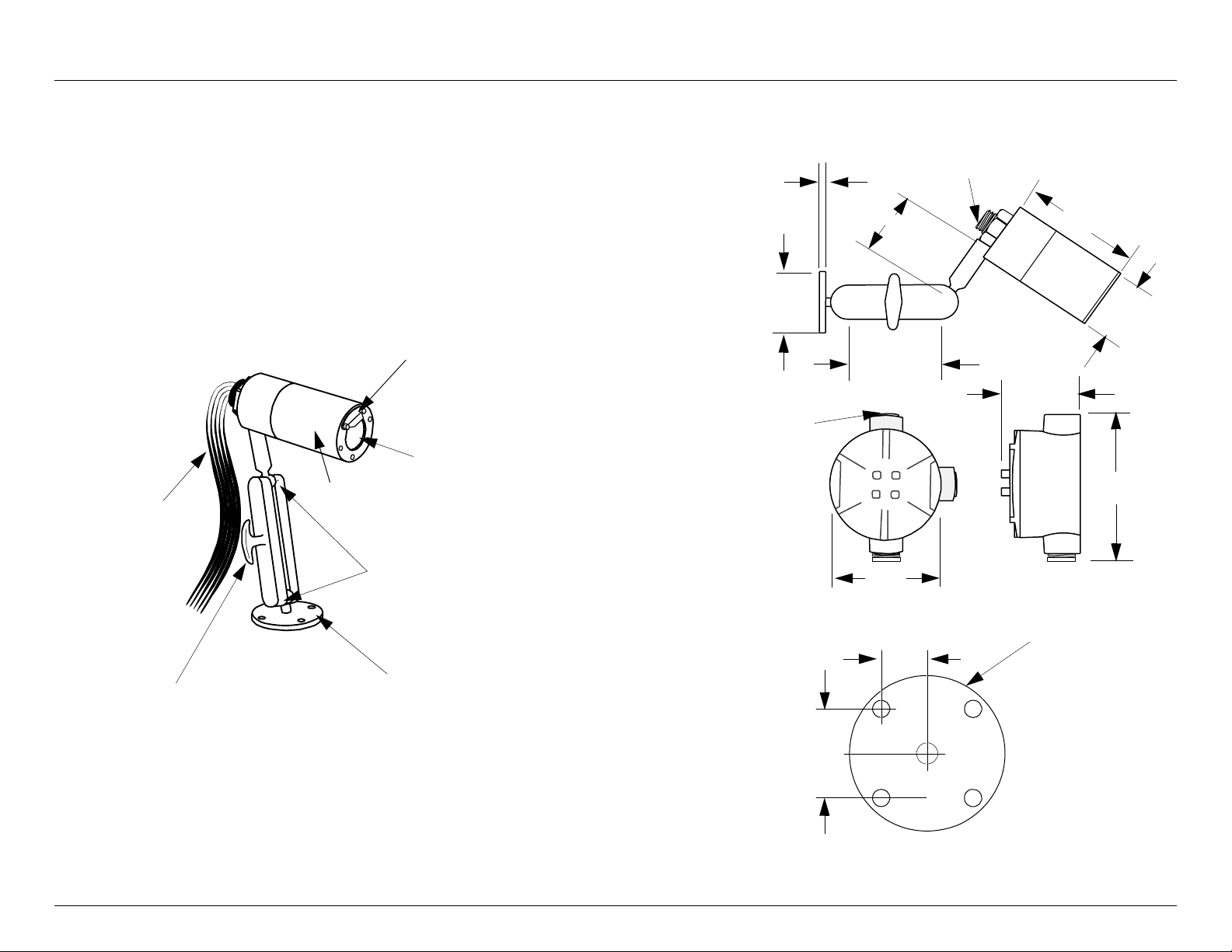
Figure 1: Detector Housing and Swivel Mount
Reflector Surface
Viewing Window
Detector Housing
Flexible
Cable
Figure 2: Dimensional Drawing
0.25”
2.50”
Fire Head
and
Swivel Mount
3/4” NPT
Junction Box
2.96”
3/4” NPT
5.89”
2.60”
4.12”
2.95”
4.850
Tighten t o
secure position
Adjustable Swivel
Mounting flange
Mounting Flange
Swivel Mount
1.015”
4.00”
2.5” diameter
Note: Units are factory sealed.
2.030”
IRS-A or AR 3
Net Safety Monitoring Inc.
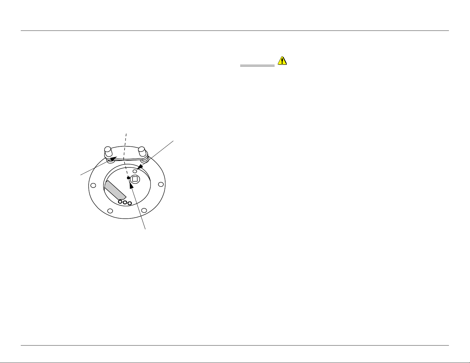
Positioning
Ensure the external gold VI reflector is placed directly over the VI Emitter
(refer to Figure 8, "Detector Viewing Window", on page 9 for VI source
location). Also ensure the detector is mounted with the VI reflector in the TOP
position, centred over the yellow dot.
Figure 3: Position of VI Reflector
Centre Line
VI Emitter
Gold VI Reflector
FIELD INSTALLATION
WARNING: Compliance with regulations is the responsibility of the
installer. Wiring must comply with applicable regulations relating to the
installation of electrical equipment in a hazardous area.
WIRING
The use of shielded cable run through conduit is highly recommended for power
input and signal wires to protect against interference caused by extraneous
electrical 'noise'. Recommended detector cable is four conductor (or greater),
shielded 18 AWG rated 300 V for distances up to 150 feet. When cable is
installed in conduit, the conduit must not be used for wiring to other electrical
equipment. Detectors can be located over 150 feet and up to 2000 feet if 16
AWG shielded conductor is used. The maximum distance between the sensor
and controller is limited by the resistance of the connecting wiring, which is a
function of the gauge of the wire being used. Refer to Appendix B, " Resistance
Table (Ohms)", on page 15.
Grounding
Proper shielding and grounding procedures, for the specific area of installation,
should always be followed.
SEALING
Water-proof and explosion-p roo f cond uit seals are recommended to prevent the
Yellow Dot
IRS-A or AR 4
accumulation of moisture within the junction box. Seals should be located as
close to the device as possible and not more than 18 inches (46 cm) away.
Explosion-proof installations may require an additional seal where conduit
enters a non-hazardous area. When pouring a seal, use a fibre dam to ensure
proper formation of the seal. Seals should never be poured at temperatures
below freezing.
The jacket and shielding of the cable should be stripped back to permit the seal
to form around the individual wires. This will prevent air , gas and water leakage
through the inside of the shield and into the enclosure.
It is recommended that explosion-proof drains and conduit breathers be used.
Changes in temperature and barometric pressure can cause 'breathing' which
allows moist air to enter conduit. Joints are seldom enough to prevent
'breathing'.
 Loading...