


FCL with 54eA Analyzer
Instruction Manual
PN 51-FCL-54eA rev.B
March 2012

This product generates, uses, and can radiate radio frequency
energy and thus can cause radio communication interference.
Improper installation, or operation, may increase such interfer-
ence. As temporarily permitted by regulation, this unit has not
been tested for compliance within the limits of Class A computing
devices, pursuant to Subpart J of Part 15, of FCC Rules, which
are designed to provide reasonable protection against such
interference. Operation of this equipment in a residential area
may cause interference, in which case the user at his own
expense, will be required to take whatever measures may be
required to correct the interference.
ESSENTIAL INSTRUCTIONS
READ THIS PAGE BEFORE PROCEEDING!
Your purchase from Rosemount Analytical, Inc. has
resulted in one of the finest instruments available for
your particular application. These instruments have
been designed, and tested to meet many national
and international standards. Experience indicates
that its performance is directly related to the quality
of the installation and knowledge of the user in operating and maintaining the instrument. To ensure
their continued operation to the design specifications, personnel should read this manual thoroughly
before proceeding with installation, commissioning,
operation, and maintenance of this instrument. If
this equipment is used in a manner not specified by
the manufacturer, the protection provided by it
against hazards may be impaired.
• Failure to follow the proper instructions may
cause any one of the following situations to
occur: Loss of life; personal injury; property damage; damage to this instrument; and warranty
invalidation.
• Ensure that you have received the correct model
and options from your purchase order. Verify that
this manual covers your model and options. If
not, call 1-800-854-8257 or 949-757-8500 to
request correct manual.
• For clarification of instructions, contact your
Rosemount representative.
• Follow all warnings, cautions, and instructions
marked on and supplied with the product.
• Use only qualified personnel to install, operate,
update, program and maintain the product.
• Educate your personnel in the proper installation,
operation, and maintenance of the product.
• Install equipment as specified in the Installation
section of this manual. Follow appropriate local
and national codes. Only connect the product to
electrical and pressure sources specified in this
manual.
• Use only factory documented components for
repair. Tampering or unauthorized substitution of
parts and procedures can affect the performance
and cause unsafe operation of your process.
• All equipment doors must be closed and protective covers must be in place unless qualified personnel are performing maintenance.
• If this equipment is used in a manner not specified by the manufacturer, the protection provided
by it against hazards may be impaired.
Equipment protected throughout by double insulation.
• Installation of cable connections and servicing of this product
require access to shock hazard voltage levels.
• Main power and relay contacts wired to separate power
source must be disconnected before servicing.
• Do not operate or energize instrument with case open!
• Signal wiring connected in this box must be rated at least
240 V.
• Non-metallic cable strain reliefs do not provide grounding
between conduit connections! Use grounding type bushings
and jumper wires.
• Unused cable conduit entries must be securely sealed by
non-flammable closures to provide enclosure integrity in
compliance with personal safety and environmental protection
requirements. Unused conduit openings must be sealed with
NEMA 4X or IP65 conduit plugs to maintain the ingress
protection rating (NEMA 4X).
• Electrical installation must be in accordance with the National
Electrical Code (ANSI/NFPA-70) and/or any other applicable
national or local codes.
• Operate only with front and rear panels fastened and in place
over terminal area.
• Safety and performance require that this instrument be
connected and properly grounded through a three-wire
power source.
• Proper relay use and configuration is the responsibility of the
user.
This product is not intended for use in the light industrial,
residential or commercial environments per the instrument’s certification to EN50081-2.
Emerson Process Management
2400 Barranca Parkway
Irvine, CA 92606 USA
Tel: (949) 757-8500
Fax: (949) 474-7250
http://www.rosemountanalytical.com
© Rosemount Analytical Inc. 2012
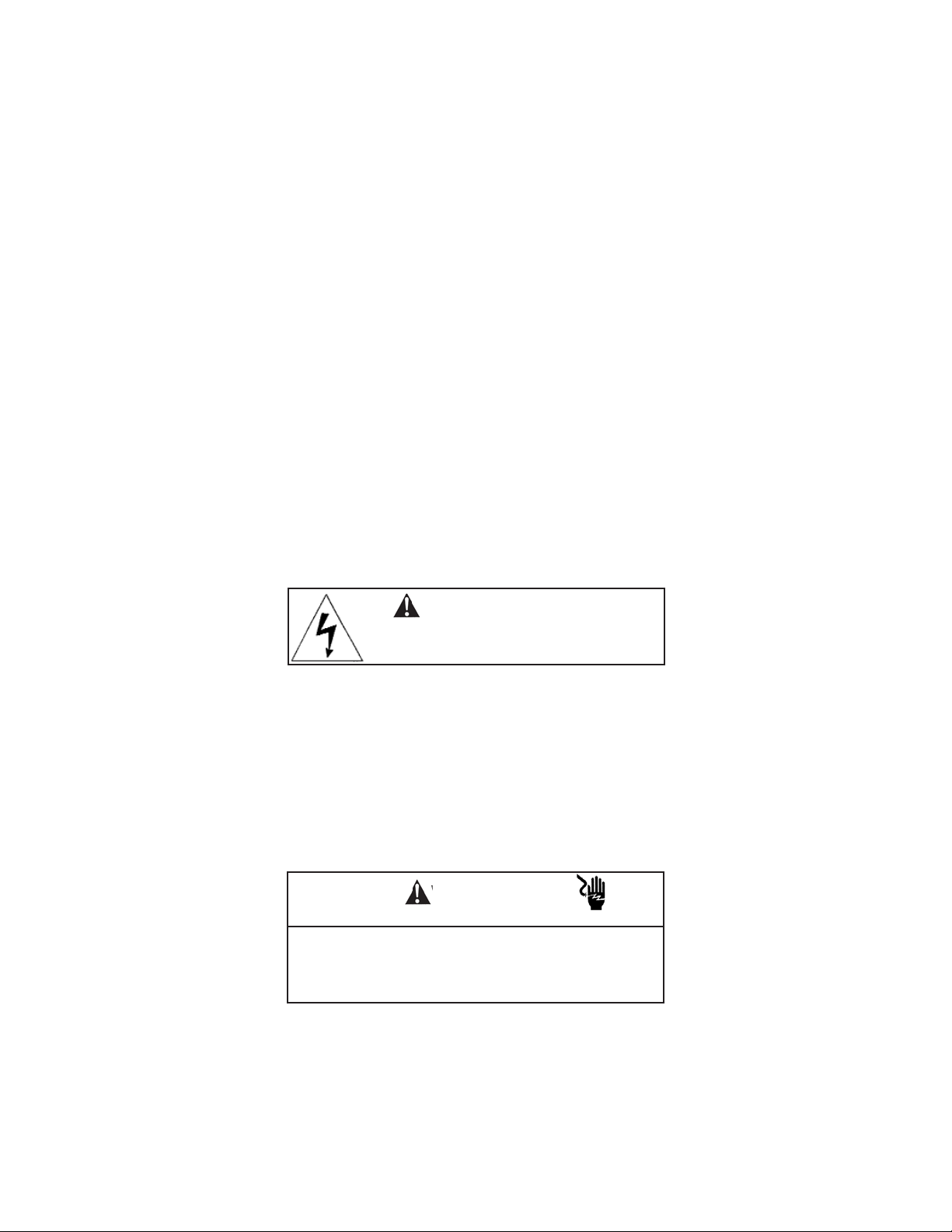
WARNING
RISK OF ELECTRICAL SHOCK
WARNING
CAUTION

About This Document
This manual contains instructions for installation and operation of the Model FCL-54eA
The following list provides notes concerning all revisions of this document.
Rev. Level
Date Notes
A 5/09 This is the initial release of the product manual. The manual has been
reformatted to reflect the Emerson documentation style and updated to
reflect any changes in the product offering.
B 3/12 Update addresses - mail and web and DNV certificate logo.

i
MODEL FCL-54eA TABLE OF CONTENTS
FCL-54eA
TABLE OF CONTENTS
Section Title Page
1.0 DESCRIPTION AND SPECIFICATIONS ................................................................ 1
1.1 Applications and Features ..................................................................................... 1
1.2 Specifications-General............................................................................................. 2
1.3 Ordering Information ................................................................................................ 3
2.0 INSTALLATION ....................................................................................................... 5
2.1 Unpacking and Inspection........................................................................................ 5
2.2 Installation................................................................................................................ 5
3.0 WIRING.................................................................................................................... 9
3.1 General .................................................................................................................... 9
3.2 Power, Alarm, and Output Wiring............................................................................. 9
4.0 DISPLAY AND OPERATION ................................................................................... 13
4.1 General Description ................................................................................................. 13
4.2 Display ..................................................................................................................... 13
4.3 Key Functions and Controls..................................................................................... 13
4.4 Alarm Status............................................................................................................. 13
5.0 PROGRAMMING THE ANALYZER ........................................................................ 15
5.1 Changing Alarm Setpoints ....................................................................................... 21
5.2 Ranging the Outputs ................................................................................................ 22
5.3 Test Outputs and Alarms.......................................................................................... 23
5.4 Chosing Display Options.......................................................................................... 24-25
5.5 Changing Output Parameters .................................................................................. 26-27
5.6 Changing Alarm Parameters .................................................................................... 28-31
5.7 Configuring the pH Measurement ............................................................................ 32
5.8 Temperature Compensation and Temperature Units ............................................... 33
5.9 Noise Reduction....................................................................................................... 34
5.10 Main Sensor Calibration Parameters ....................................................................... 35
5.11 Security ....................................................................................................................36
5.12 Analyzer Mode Priority............................................................................................. 37
6.0 CALIBRATION - TEMPERATURE .......................................................................... 39
6.1 Introduction .............................................................................................................. 39
6.2 Temperature Calibration........................................................................................... 40

Section Title Page
7.0 CALIBRATION CHLORINE .................................................................................... 41
7.1 Introduction .............................................................................................................. 41
7.2 Zeroing the Sensor .................................................................................................. 42
7.3 Full Scale Calibration ............................................................................................... 43
7.4 Dual Slope Calibration ............................................................................................. 44
8.0 CALIBRATION - CURRENT OUTPUTS ................................................................. 47
8.1 Introduction .............................................................................................................. 47
8.2 Trimming the Outputs............................................................................................... 47
9.0 MAINTENANCE ..................................................................................................... 49
9.1 Analyzer ................................................................................................................... 49
9.2 Chlorine Sensor ....................................................................................................... 50
9.3 Constant Head Flow Controller................................................................................ 52
10.0 TROUBLESHOOTING ........................................................................................... 55
10.1 Overview .................................................................................................................. 55
10.2 Troubleshooting When a Fault Message is Showing............................................... 55
10.3 Troubleshooting When No Fault Message is Showing - Temperature..................... 56
10.4 Troubleshooting When No Error Message is Showing - Chlorine............................ 56
10.5 Troubleshooting When No Error Message is Showing - General ............................ 59
10.6 Simulating Inputs - Chlorine..................................................................................... 59
10.7 Simulating Inputs - Temperature............................................................................... 60
LIST OF TABLES
Number Title Page
5.1 Program Settings List ............................................................................................... 15-17
5.2 Controller Mode Priority Chart.................................................................................. 37
10.2 Troubleshooting When a Fault Message is Showing ............................................... 55
10.4 Troubleshooting When No Error Message is Showing - Chlorine ............................ 56
10.5 Troubleshooting When No Error Message is Showing - General............................. 59
MODEL FCL-54eA TABLE OF CONTENTS
TABLE OF CONTENTS CONT’D
ii

LIST OF FIGURES
Number Title Page
2-1 Chlorine Sensor Parts .............................................................................................. 7
2-2 Model FCLi-01-230................................................................................................... 8
3-1 Power Input and Relay Output Wiring for Model 54eA ............................................ 10
3-2 Wiring Label .................................................................................................... 11
3-3 Wiring Sensor to Model 54eA Analyzer ...................................................................... 11
4-1 Main Display Screen ................................................................................................ 13
5-1 Menu Tree for the 54eA Controller .......................................................................... 18-20
5-2 Low Alarm ................................................................................................................ 30
5-3 High Alarm................................................................................................................ 30
5-4 Interval Timer............................................................................................................ 31
7-1 Sensor Current as a Function of Free Chlorine Concentration ................................ 41
7-2 Dual Slope Calibration.............................................................................................. 44
9-1 Chlorine Sensor Parts ............................................................................................. 51
9-2 Replacement Parts for the Flow Controller Assembly.............................................. 53
10-3 Three-Wire RTD Configuration................................................................................. 60
10-4 Simulating RTD Inputs.............................................................................................. 60
iii

Model FCL-54eA SECTION 1.0
DESCRIPTION AND SPECIFICATIONS
SECTION 1.0.
DESCRIPTION AND SPECIFICATIONS
1
• COMPLETE SYSTEM INCLUDES sensors, connecting cables, analyzer, and flow controller.
• CONTINUOUS pH CORRECTION eliminates expensive and messy reagents and troublesome sample conditioning systems.
• MEASURES FREE CHLORINE IN SAMPLES having pH as high as 9.5.
1
• VARIOPOL QUICK-DISCONNECT FITTINGS make replacing sensors easy.
1
In some cases, the sensor can be used in samples having pH as great as 10.0. Consult the factory.
1.1 APPLICATIONS
The FCL free chlorine system is intended for the
determination of free chlorine in fresh water. Unlike
free chlorine analyzers from other manufacturers, the
FCL does not use expensive sample conditioning systems or messy reagents to control pH. Instead, the
analyzer automatically compensates for changes in
the pH of the sample. The FCL is not intended for the
determination of total chlorine or combined chlorine
(like monochloramine). Nor, can the FCL be used for
the determination of chlorine in seawater.
1.2 FEATURES
The FCL uses a membrane-covered amperometric
sensor. A polarizing voltage applied to a platinum
cathode behind the membrane destroys any chlorine
that diffuses through the membrane, keeping the concentration of chlorine in the sensor equal to zero. The
current generated by the cathode reaction is proportional to the rate of diffusion of chlorine through the
membrane. Because the concentration of chlorine in
the sensor is zero, the diffusion rate and the current
are proportional to the concentration of chlorine.
There is a difficulty, however. Amperometric free
chlorine sensors measure only hypochlorous acid.
Because free chlorine is a pH-dependent mixture of
hypochlorous acid and hypochlorite ion, a change in
pH will cause the sensor response to change even
though the free chlorine level remained constant.
Most manufacturers solve the problem by treating the
sample with acid, which lowers the pH and converts
hypochlorite ion into hypochlorous acid. The
FCL
avoids the expense and inconvenience of
sample
conditioning by measuring the pH and applying a cor-
rection to the raw chlorine sensor signal. The correction is valid between pH 6.0 and 9.5. Below pH 6.0,
no correction is needed. For samples having pH
between 9.5 and 10.0, consult the factory.
The FCL is available in two options: Model FCL-01
with manual pH correction and Model FCL-02 with
continuous pH correction. Choose the FCL-01 if
the
pH varies less than 0.2 or if pH changes are
predictable or seasonal. Choose the FCL-02 if the pH
varies more than 0.2. To provide the continuous pH
correction, the Model FCL-02 requires a separate pH
sensor.
Maintenance is fast and easy. Replacing a membrane
requires no special tools or fixtures. A screw cap holds
the pre-tensioned membrane in place. Replacing the
electrolyte solution takes only minutes.
The FCL includes the easy-to-use Model 54eA
analyz-
er. The analyzer features two fully programmable
4-20
mA analog outputs and three alarm relays.
Programming and calibration are simple and intuitive.
The large backlit display allows the user to read
chlorine at a single glance.
Valves, rotameters, and pressure regulators to control
sample flow are things of the past with the Model FCL.
A constant head overflow sampler ensures the correct
sample flow to the sensors. To eliminate wiring
hassles, quick-disconnect Variopol cable is standard.
Stable free chlorine standards do not exist. The
chlorine sensor must be calibrated using the results of
a laboratory test run on a grab sample.
2
MODEL FCL-54eA SECTION 1.0
DESCRIPTION AND SPECIFICATIONS
SPECIFICATIONS — GENERAL
Sample requirements:
Pressure: 3 to 65 psig (122 to 549 kPa abs)
A check valve in the inlet prevents the sensor
flow cells from going dry if sample flow is lost.
The check valve opens at 3 psig (122 kPa abs).
If the check valve is removed, minimum pressure is 1 psig (108 kpa abs).
Temperature: 32 to 122°F (0 to 50°)
Minimum Flow: 3 gal/hr (11 L/hr)
Maximum flow: 80 gal/hr (303 L/hr); high flow
causes the overflow tube to back up.
Sample Conductivity: >50 µS/cm at 25°C
Process connection: 1/4-in OD tubing compression
fitting (can be removed and replaced with a
barbed fitting for use with soft tubing).
Drain connection: 3/4-in barbed fitting. Sample must
drain to open atmosphere.
Wetted parts:
Overflow sampler and flow cell: acrylic, polycar-
bonate, Kynar®1, nylon, silicone
Chlorine sensor: Noryl®2, Viton®3, wood, silicone,
polyethersulfone, polyester, and platinum
pH sensor: Tefzel®4, Viton, glass, ceramic
Response time to step change in chlorine concen-
tration: <80 sec to 95% of final reading for inlet
sample flow of 3 gph (11 L/hr).
Weight/shipping weight:
Model FCL-01-230: 10 lb/13 lb (4.5 kg/6.0 kg)
Model FCL-02-230: 11 lb/14 lb (5.0 kg/6.5 kg)
[rounded to the nearest 1 lb. (0.5 kg)]
SPECIFICATIONS — SENSOR
Free chlorine range: 0 to 10 ppm as Cl2. For higher
ranges, consult the factory.
pH correction range: 6.0 to 9.5. For samples having
pH between 9.5 and 10.0, consult the factory.
For manual pH correction, choose option -01.
For continuous pH correction choose option -02.
Accuracy: Accuracy depends on the accuracy of the
chemical test used to calibrate the sensor.
Electrolyte volume: 25 mL (approx.)
Electrolyte life: 3 months (approx.); for best results
replace electrolyte monthly.
SPECIFICATIONS — MODEL 54eA
ANALYZER
Case: Epoxy-painted cast aluminum, NEMA4X (IP65).
Front Panel: Membrane keypad with tactile feedback.
Three green LEDs indicate alarm status. Red
LED indicates fault condition.
Conduit Openings: Accepts PG 13.5 or 1/2 inch con-
duit fittings
Display: Three-line, back-lit, dot matrix LCD, 70 x 35 mm.
First line is measurement reading. Second line is
temperature and current output. Third line is userselectable. Character heights: 1st line - 16 mm
(0.6 in.), 2nd and 3rd lines - 7 mm (0.3 in.).
Ambient Temperature and Humidity: 0 to 50°C (32
to 122°F). 95% (maximum) non-condensing.
Analyzer can be operated between -20 and 60°C
(-4 to 140°F) with some degradation in display
quality.
Power: 100-127 Vac ± 10%, 50/60 Hz ± 6%, 8 W
200-253 Vac ± 10%, 50/60 Hz ± 6%, 8 W
RFI/EMI: EN-61326
LVD: EN-61010-1
Outputs: Two 4-20 mA or 0-20 mA isolated outputs.
Continuously adjustable. Outputs can be
assigned to chlorine or temperature. Output
dampening is user-selectable. Maximum load
at 115/230 Vac is 600Ω. Maximum load at
100/200 Vac is 550Ω.
Alarms: Three alarm relays for process measurement,
temperature or interval timer. The fourth alarm
relay is a sensor/analyzer fault alarm.
Relay Contacts: Relays 1-3: Form A, SPST, NO,
epoxy sealed. Relay 4: Form C, SPDT, epoxy
sealed
1
Kynar is a registered trademark of Elf Atochem North America.
2
Noryl is a registered trademark of General Electric.
3
Viton is a registered trademark of E.I. duPont de Nemours & Co.
4
Tefzel is a registered trademark of E.I. duPont de Nemours & Co
Resistive Inductive
28 Vdc 5.0 3.0
115 Vac 5.0 3.0
230 Vac 5.0 1.5

SECTION 2.0.
INSTALLATION
MODEL FCL-54eA SECTION 2.0
INSTALLATION
3
2.1 UNPACKING AND INSPECTION
Inspect the shipping container. If it is damaged, contact the shipper immediately for instructions. Save the box. If
there is no apparent damage, unpack the container. Be sure all items shown on the packing list are present. If
items are missing, notify Rosemount Analytical immediately.
2.1.1 FCL-01-230 (free chlorine without continuous pH correction)
Model FCL-01-230 consists of the following items mounted on a back plate.
1. Model 54eA-01 analyzer with sensor cable attached.
2. Constant head overflow sampler with flow cell for chlorine sensor.
The free chlorine sensor (Model 499ACL-01-54-VP), shipped with three membrane assemblies and a bottle of
electrolyte solution, are in a separate package.
2.1.2 FCL-02-230 (free chlorine with continuous pH correction)
Model FCL-02-230 consists of the following items mounted on a back plate.
1. Model 54eA-01 analyzer with sensor cables attached.
2. Constant head overflow sampler with flow cells for pH and chlorine sensors.
3. Stand to hold pH buffer solution during calibration.
The free chlorine sensor (Model 499ACL-01-54-VP), shipped with three membrane assemblies and a bottle of
electrolyte solution, and the Model 399VP-09 pH sensor are in separate packages.

4
MODEL FCL-54eA SECTION 2.0
INSTALLATION
2.2 INSTALLATION
2.2.1 General Information
1. Although the system is suitable for outdoor use, do not install it in direct sunlight or in areas of extreme temperature.
2. To keep the analyzer enclosure watertight, install plugs (provided) in the unused cable openings.
3. Install the system in an area where vibrations and electromagnetic and radio frequency interference are minimized or absent.
4. Be sure there is easy access to the analyzer and sensors.
2.2.2 Sample Requirements
Be sure the sample meets the following requirements:
1. Temperature: 32 to 122ºF (0 to 50ºC)
2. Pressure: 3 to 65 psig (122 to 549 kPa abs)
3. Minimum flow: 3 gal/hr (11 L/hr)
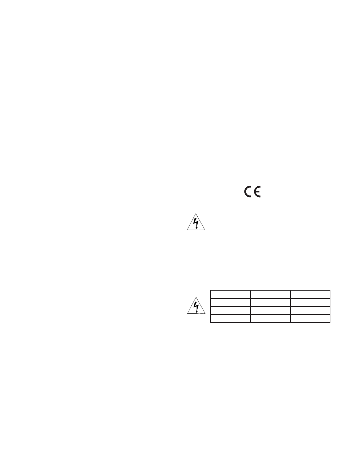
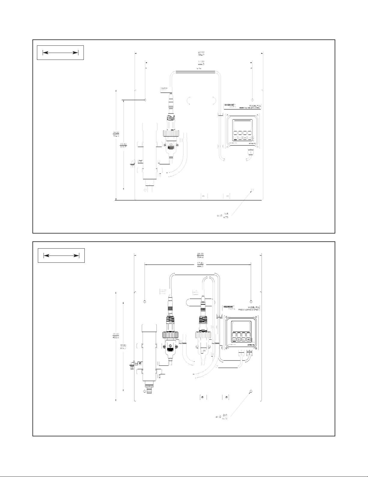
2.2.3 Mounting, Inlet, and Drain Connections
The Model FCL is intended for wall mounting only. Refer to Figure 2-1 or 2-2 for details. The sensor(s) screw into
the flow cell adapters as shown in the figures. For Model FCL-02 (free chlorine with continuous pH adjustment),
the pH sensor must be installed as shown in Figure 2-2.
A 1/4-inch OD tubing compression fitting is provided for the sample inlet. If desired, the compression fitting can
be removed and replaced with a barbed fitting. The fitting screws into a 1/4-inch FNPT check valve. The check
valve prevents the sensor flow cells from going dry if sample flow is lost.
The sample drains through a 3/4-inch barbed fitting. Attach a piece of soft tubing to the fitting and allow the waste
to drain open atmosphere. Do not restrict the drain line.
Remove the foam packing insert between the outer tube and the inner overflow tube. Adjust the sample flow
until the water level is even with the central overflow tube and excess water is flowing down the tube.
2.2.4 Electrical Connections
Refer to Section 3.1 for details.
2.2.5 Installing the Sensor(s)
The Model FCL is provided with sensor cables pre-wired to the analyzer. Connect the chlorine sensor (Model
499ACL-01-54-VP) to the cable labeled CHLORINE. Connect the pH sensor (Model 399VP-09) to the cable
labeled pH. The terminal end of the sensor is keyed to ensure proper mating with the cable receptacle. Once the
key has slid into the mating slot, tighten the connection by turning the knurled ring clockwise.
The sensor(s) screw into the plastic fitting(s), which are held in the flow cell(s) by the union nut. Do not remove the
protective cap on the sensor(s) until ready to put the sensor(s) in service.
Model FCL-54eA SECTION 2.0
INSTALLATION
FIGURE 2-1. Model FCL-01
FIGURE 2-2. Model FCL-02
INCH
MILLIMETER
INCH
MILLIMETER
5

This page left blank intentionally
6
MODEL FCL-54eA SECTION 2.0
INSTALLATION
SECTION 3.0.
WIRING
MODEL FCL-54eA SECTION 3.0
WIRING
7
3.1 GENERAL
WARNING
Electrical installation must conform to the National Electrical Code, all state and local codes, and all plant
codes and standards for electrical equipment. Electrical installation and wiring must be done by qualified
personnel.
The five holes in the bottom of the instrument case accept 1/2-in. strain relief connectors or conduit fittings. The
rear openings are for power and alarm relay wiring. The left front opening is for sensor wiring (already installed)
and the right front opening is for analog output wiring. Seal unused openings with conduit plugs.
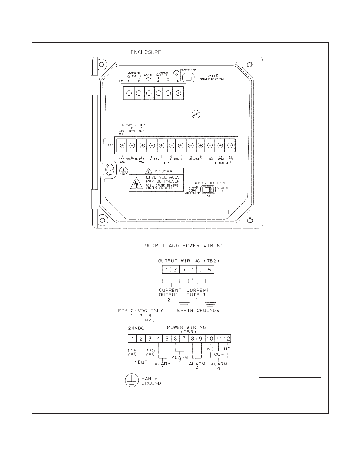
3.2 POWER, ALARM, AND OUTPUT WIRING
Refer to Figure 3-1. Make power and alarm connections on TB3. Make analog output wiring connections on TB2. For
access to power and alarm terminals, loosen the screw holding the protective cover in place and remove the cover.
Alarm contacts are dry (i.e., not powered) and are normally open. Refer to Section 1.0 for relay specifications.
For best EMI/RFI protection, shield the output cable and enclose it in an earth-grounded, rigid, metal conduit.
Connect the outer shield of the output cable to the earth ground connection on TB2 (see Figure 3-1).
Keep sensor and output signal wiring separate from power wiring. Do not run sensor and power cables in the same
conduit or close together in a cable tray.
AC wiring must be 14 gauge or greater. Be sure to connect earth ground from the power cable to the nearby
ground lug. A good earth ground is necessary for proper operation of the controller. Provide a switch or breaker to
disconnect the analyzer from the main power supply. Install the switch or breaker near the analyzer and label it as
the disconnecting device.
NOTE
The Model 54eA analyzer leaves the factory configured to measure dissolved oxygen, not free
chlorine. Before connecting the sensor to the cable, configure the analyzer to measure free chlorine. See section 5.4
Live voltages may be present. Will
cause severe injury or death
DANGER
WARNING
RISK OF ELECTRICAL SHOCK
AC connections and grounding must comply with UL
508 or local electrical code. DO NOT apply power to
the analyzer until all electrical connections are verified and secure.
WARNING
MODEL FCL-54eA SECTION 3.0
WIRING
8
FIGURE 3-1. Power Input and Relay Output Wiring for Model 54eA
DWG. NO. REV.
454EPH02 D
9
MODEL FCL-54eA SECTION 3.0
WIRING
FIGURE 3-2. Wiring Label
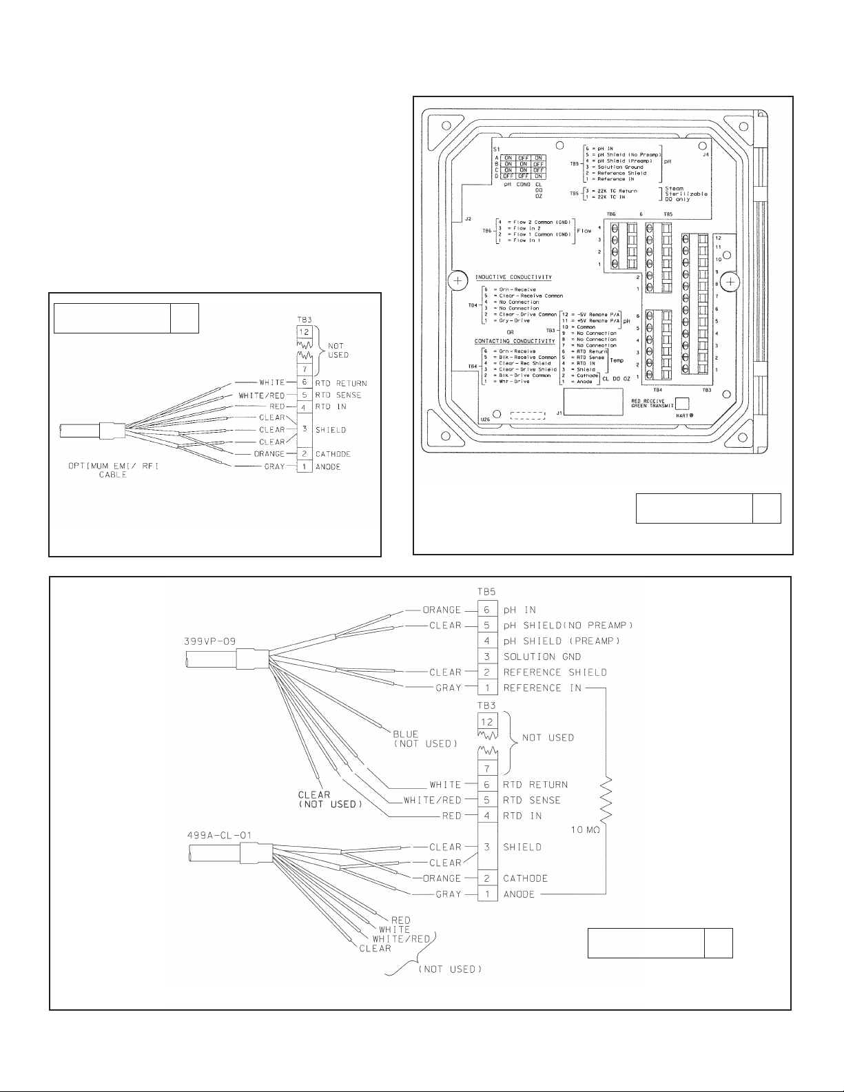
3.3 SENSOR WIRING
3.3.1 General
The wiring label is a general purpose label. It
has wiring information concerning other
sensors, for example, contacting and inductive
conductivity sensors, that can be used with the
54e instrument platform. The Model FCLi is
provided with sensor cable pre-wired to the
analyzer. If it is necessary to replace the
cable, refer to Figures 3-2 (wiring label) and
3-3 and 3-4 (wiring diagrams).
DWG. NO. REV.
40054e03 A
FIGURE 3-3. Wiring Chlorine Sensor to
Model 54eA Analyzer
FIGURE 3-4. Wiring Chlorine and pH Sensor to 54eA Analyzer.
DWG. NO. REV.
4054eA02 B
DWG. NO. REV.
40499A24 A

This page left blank intentionally
10
MODEL FCL-54eA SECTION 3.0
WIRING

11
MODEL FCL-54eA SECTION 4.0
DISPLAY AND OPERATION
SECTION 4.0
DISPLAY AND OPERATION
4.1 GENERAL DESCRIPTION
The 54eA analyzer is a single input, dual output instrument. It does, however, accept a second input for pH
when the main measurement is free chlorine.
4.2 DISPLAY
Figure 4-2 shows the main display.
4.3 KEY FUNCTIONS AND CONTROLS
The keys labeled F1, F2, F3, and F4 are multi-function.
The function appears in the main display just above the
key. For example, F1 is usually labeled Exit and F4
may be labeled Edit, Save, or Enter.
1. To enter the main menu, press any key.
2. Use the é and ê keys to move the cursor to the
desired sub-menu. The position of the cursor is
shown in reverse video.
NOTE
When the last item of a menu has been
reached, the cursor will be on the third line
of the display. If the cursor is on the second
line of the display more items remain.
Continue pressing the ê key.
3. Press Enter (F4) to access a sub-menu or an item
in a sub-menu.
4. To change a number or a setting press Edit (F4).
The display will change to show the cursor on the
first digit or on a + or - sign. Use the é and ê keys
to increase or decrease a digit or to toggle the +
and - signs. Use the ç and è keys to move the
cursor left and right.
5. If an entire number or a word is highlighted, use the
é and ê keys to scroll through the list of choices.
6. To store a number or setting in memory, press
Save (F4).
7. To leave without storing changes, press Esc (F3).
8. To leave and return to the previous screen, press
Exit (F1).
9. To end a calibration step and leave the previous
calibration in place, press Abort (F1).
10. Occasionally, information screens will appear. To
leave the information screen and move to the next
screen press Cont (F3).
4.4 ALARM STATUS
Green LEDs (labeled 1, 2, and 3) indicate when alarm
relays 1, 2, and 3 are energized. The fourth relay indicates a fault condition. When a fault occurs, the red
LED (labeled FAIL) lights up, a descriptive error message appears, and the outputs and alarm relays act as
programed in Sections 5.5 and 5.6.
The red LED also indicates when the interval timer
routine is activated and when the time limit has been
reached on a feed limit timer. For more information on
these subjects, see Section 5.6.
FIGURE 4-1. Main Display Screen
Chlorine is always displayed continuously in large
numerals. The temperature and output current are
always displayed on the second line of the main display.
The third line can be configured by the user. In the example, the third line shows the pH readings and the raw
sensor current in nA.
1.00 ppm
26.2°C. 12.00 mA
pH: 8.00 I: 340 nA

This page left blank intentionally
12
MODEL FCL-54eA SECTION 4.0
DISPLAY AND OPERATION

13
SECTION 5.0
PROGRAMMING THE ANALYZER
MODEL FCL-54eA SECTION 5.0
PROGRAMMING THE ANALYZER
The Model 54eA analyzer can be used to measure dissolved oxygen, ozone, total chlorine, and monochloramine
in addition to free chlorine. It is configured at the factory to measure dissolved oxygen. Before connecting the
sensor to the cable, the analyzer must be configured to measure free chlorine. See section 5.4.
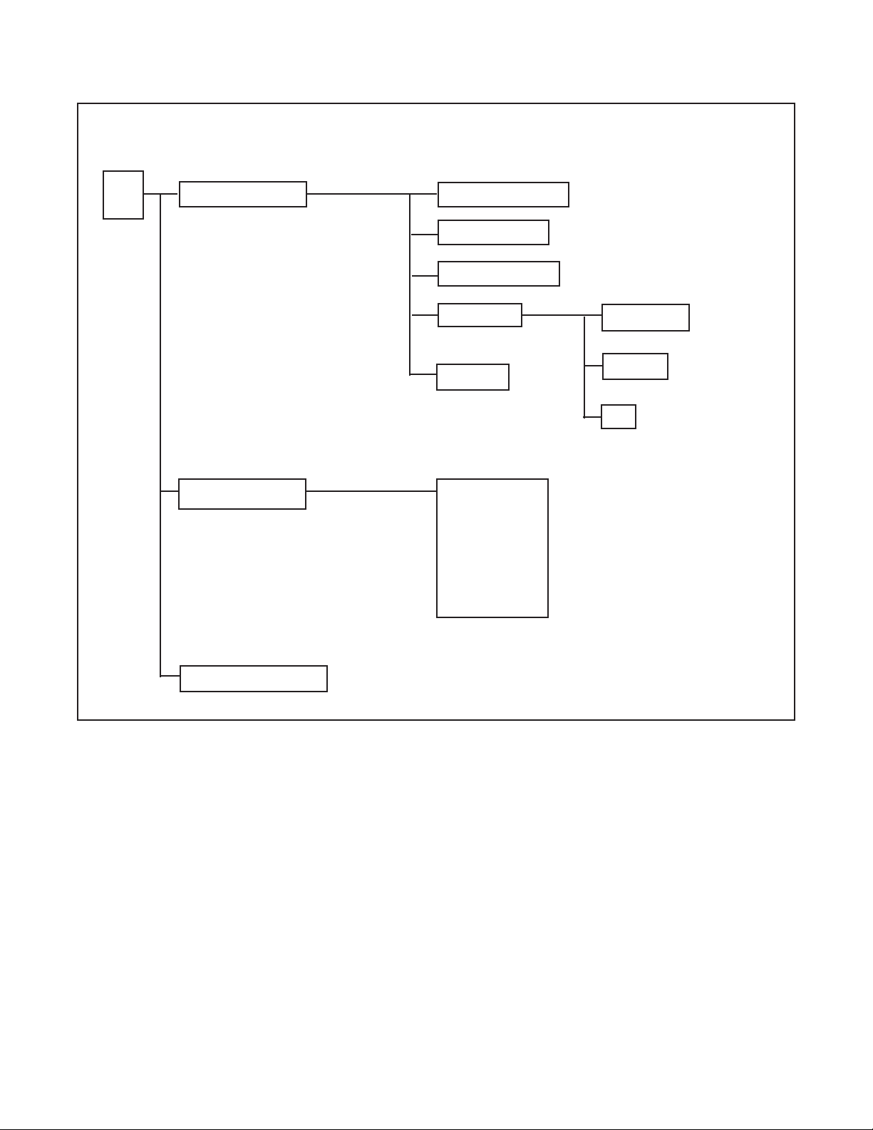
Figure 5-1 is an outline of the analyzer menu structure. Settings that do not apply to the measurement of free chlorine
are grayed out. Settings that apply to PID and TPC control and HART digital communications, features not
available in the analyzer option provided with the FCL, are also grayed out.
Table 5-1 list the default settings and the choices available for each setting. Only the choices available for free
chlorine are shown.
TABLE 5-1. Program Settings List
Continued on the following page
ITEMS CHOICES FACTORY SETTINGS
A. Alarms setpoints (Section 5.1)
1. Alarm 1 (low action)
a. if chlorine -9999 to 9999 ppm 0 ppm
b. if temperature -5 to 130°C 0.1°C
2. Alarm 2 (high action)
a. if chlorine -9999 to 9999 ppm 20 ppm
b. if temperature -5 to 130°C 130°C
3. Alarm 3 See alarm 2 See alarm 2
B. Output ranging (Section 5.2)
1. Output 1 or 2: 4 mA setting
a. if chlorine -9999 to 9999 ppm 0 ppm
b. if temperature -5 to 130°C 0.1°C
2. Output 1 or 2: 20 mA setting
a. if chlorine -9999 to 9999 ppm 20 ppm
b. if temperature -5 to 130°C 130°C
C. Display options (Section 5.4)
1. Measurement Oxygen, ozone, free chlorine, total chlorine, monochloramine Oxygen
2. Temperature units °C or °F °C
3. Output 1 mA or % of full scale mA
4. Output 2 mA or % of full scale mA
5. Language English, Français, Español, Deutsch, Italiano English
6. Main display left See section 5.4 Sensor current
7. Main display right See section 5.4 Output 1 current
8. Display contrast 00-99 (darkest) 50
9. Test timeout On or off On
10. Timeout value 1 to 60 min 10 min
D Output parameters (Section 5.5)
1. Output 1 Control
a. Measurement Oxygen, chlorine, ozone, pH, or temperature Oxygen
b. Control Normal Normal

14
MODEL FCL-54eA SECTION 5.0
PROGRAMMING THE ANALYZER
ITEMS CHOICES FACTORY SETTINGS
D. Outputs (Section 5.5) (continued)
2. Output 1 Setup (normal)
a. Current 4-20 mA or 0-20 mA* 4-20 mA
b. Dampening 0-299 sec 0 sec
c. Hold mode Hold last value or go to fixed value Hold last value
d. Fixed hold value 0-22 mA 21 mA
e. Fault value 0-22 mA 22 mA
3. Output 2 See output 1 See output 1
4. Hold feature Enable, disable, or 20 min timeout Disable
E. Alarms parameters (Section 5.6)
1. Alarm 1 Control
a. Activation method Oxygen, chlorine, ozone, temperature, pH Oxygen
b. Control mode Normal Normal
2. Alarm 1 setup (normal)
a. Configuration Low, high, or off High
b. Hysteresis
if chlorine -9999 to 9999 ppm 0 ppm
if temperature 0 to 10°C 0.1°C
c. Delay time 0-99 sec 0 sec
d. Relay fault none, open, closed None
3. Alarm 2 Control
a. Activation method Oxygen, chlorine, monochloramine, ozone, temperature, pH Oxygen
b. Control mode Normal Normal
4. Alarm 2 setup (normal)
a. Configuration Low, high, or off Low
Rest of alarm 2 setup is the same as alarm 1
5. Alarm 3 control and setup is the same as alarm 1
6. Alarm 4 control
Alarm Fault or off Fault
7. Feed limit timer
a. Feed limit Disable, alarm 1, alarm 2, or alarm 3 Disable
b. Timeout value 0 to 10,800 sec 600 sec
8. Interval timer
a. Select alarm Disable, alarm 1, alarm 2, or alarm 3 Disable
b. Interval time 0 to 999.9 hr 24.0 hr
c. Repeats 1 to 60 1
d. On time 0 to 2999 sec 120 sec
e. Off time 0 to 2999 sec 1 sec
f. Recovery time 0 to 999 sec 600 sec
F. Temperature compensation (Section 5.8)
1. Temperature compensation Auto or manual Auto
2. Manual temperature -15 to 130°C 25°C
TABLE 5-1. Program Settings List (continued)
Continued on the following page

15
MODEL FCL-54eA SECTION 5.0
PROGRAMMING THE ANALYZER
TABLE 5-1. Program Settings List (continued)
ITEMS CHOICES FACTORY SETTINGS
G. Noise Reduction (section 5.9)
Noise rejection 50 or 60 Hz 60 Hz
H. Main sensor calibration (Section 5.10)
1. Stabilize reading (Chlorine) 0 to 999 ppm 0.05 ppm
2. Stabilize time 0 - 30 sec 10 sec
3. Sensor zero stabilization value
4. Dual range calibration Enable or disable disable
I. Security (Section 5.11)
1. Lock all 000-999 (000 disables) 000
2. Lock program 000-999 (000 disables) 000
3. Lock configuration 000-999 (000 disables) 000
16
MODEL FCL-54eA SECTION 5.0
PROGRAMMING THE ANALYZER
FIGURE 5-1. Menu Tree for the 54eA Controller
Calibrate
Program (see page 17)
Diagnostic Variables
Main
Menu
Calibrate main sensor
Zero main sensor
Adjust temperature
Calibrate pH
Slope
Buffer calibration
Standardize
Main measurement
Main sensor current
Sensitivity (µA/ppm)
Zero current
pH reading
pH mV reading
pH slope (mV/pH)
pH offset
Glass impedance
Noise rejection
Software version
Output trim

17
MODEL FCL-54eA SECTION 5.0
PROGRAMMING THE ANALYZER
Program
Calibrate (see page 16)
Diagnostic Variable (see page 16)
Main
Menu
Alarms 1, 2, and 3 setpoints
4 mA or 0 mA
20 mA
Present output current
Alarm Setpoints
Output setpoints
Test output 1 or 2
Test alarm 1, 2, 3, or 4
Simulated tests
Configure
Display
Main
Sensor
Oxygen
Free Chlorine
Total Chlorine
Monochloramine
Ozone
Outputs
Output 1 and 2
control
Measurement: main snr, pH, temp.
Control mode: normal, PID
Output 1 and 2
setup
Range (0-20 or 4-20 mA)
Dampen*
Hold - keep last value
Hold - go to specified value
Fault
Setpoint, proportional, integral
Derivative**
Hold feature setup
*Normal only
**PID only
Alarms
Alarm 1, 2, & 3
control
Measurement: main snr, pH, temp.
Control mode: normal, TPC
Alarm 1, 2, & 3
setup
Alarm: High, low, or off*
Setpoint
Hysteresis*
Delay*
Time period, URV, LRV**
Relay default
Interval timer
Timer: Alarm 1, 2, or 3 or disable
Interval
Repeats
On time
Off time
Recovery time
Alarm 4 setup
Feed limit timer
Feed limit: Alarm 1, 2, or 3 or disable
Timeout
*Normal only **TPC only
Continued on page 20
FIGURE 5-1. Menu Tree for the 54eA Controller
(continued)
Sensor type and manufac.
Units: ppm, ppb, % sat
°C or °F
Output 1 (mA or %FS)
Output 2 (mA or %FS)
Language
Line 3 display
Display contrast
Timeout (on or off)
Timeout - limit
Polling address

18
MODEL FCL-54eA SECTION 5.0
PROGRAMMING THE ANALYZER
FIGURE 5-1. Menu Tree for the 54eA Controller (continued)
Display (see page 17)
Outputs (see page 17)
Alarms (see page 17)
Program
Calibrate (see page 16)
Diagnostic Variable (see page 16)
Main
Menu
Alarm Setpoints (see page 17)
Output setpoints
(see page 17)
Simulated tests
(see page 17)
Configure
pH
(available with free
chlorine only)
Disable
Enable
pH
diagnostics
Diagnostics: on or off
Glass impedance high
Glass impedance low
Zero offset
Impedance temp comp: on or off
Temperature
Temperature comp: auto or manual
Units: °C or °F
Noise
Rejection
Noise rejection: 50 or 60 Hz
Barometric
Pressure
Measurement: Auto or manual
Units: mm Hg, kPa, atm, barg, in Hg
Main sensor cal
Stabilize conc’n
Stabilize time
Salinity (oxygen only)
Security
pH
calibration
Autocal: standard, manual, Merck,
Ingold, DIN 19267
Stabilize pH
Stabilize time
Temperature
coefficient
Temperature coeff
Operating isopotential
Sensor isopotential
Lock all
Lock program
Lock configure
(oxygen only)

19
MODEL FCL-54eA SECTION 5.0
PROGRAMMING THE ANALYZER
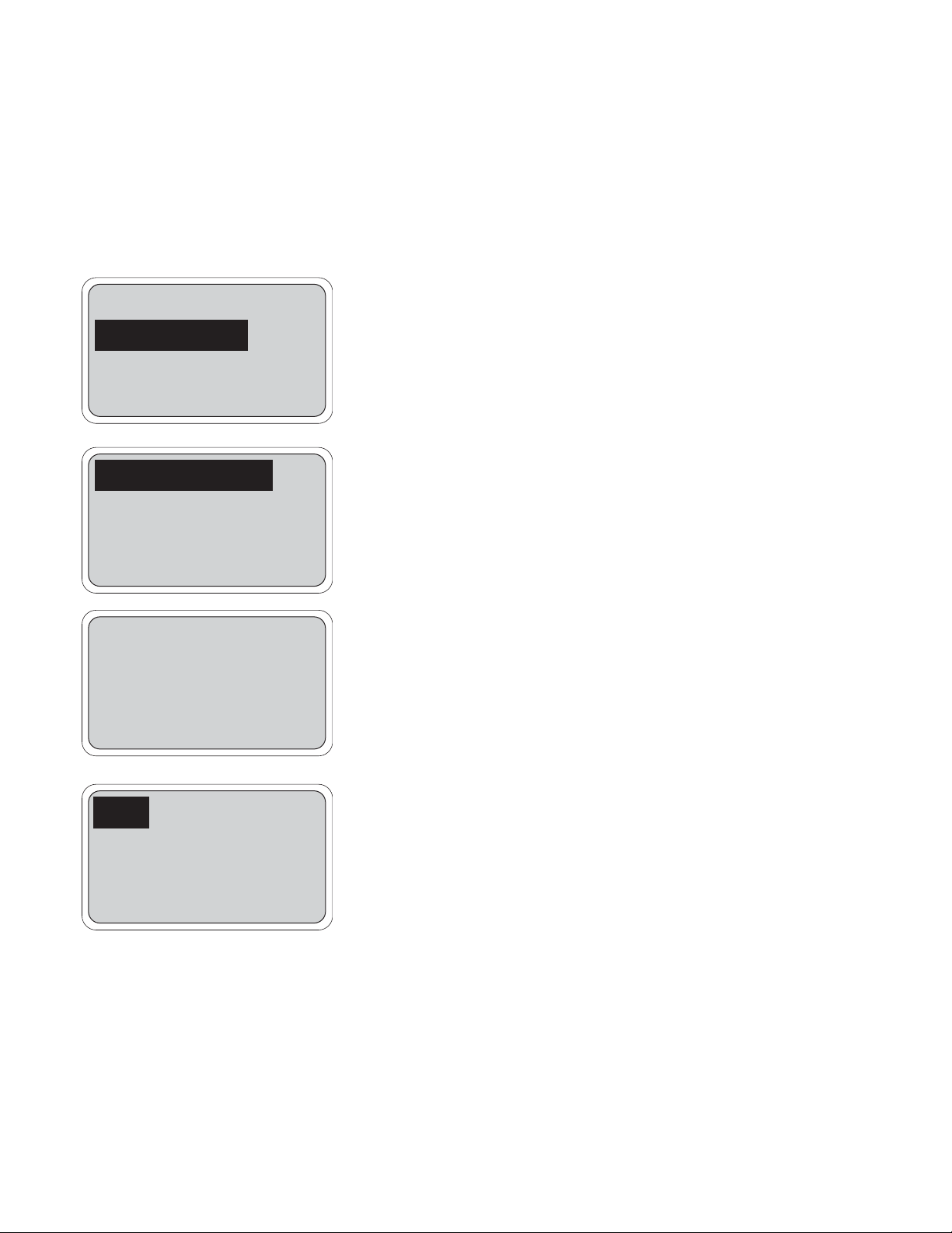
5.1 CHANGING ALARM SETPOINTS
2. Press any key to enter the main menu. Move the cursor to "Program"
and press Enter (F4).
3. Press Enter (F4).
4. Move the cursor to the desired alarm and press Enter (F4).
5. A screen like the one shown will appear. The alarm is a low alarm
and the setpoint is 0.00 ppm. Press Edit (F4). Use the arrow keys to
change the setpoint. Press Save (F4) to store the new value. Press
Exit (F1) to return to the screen in step 4. Choose a new alarm.
Alarm setpoints
Output setpoints
Simulate tests
Exit Enter
Alarm 1 setpoint
Alarm 2 setpoint
Alarm 3 setpoint
Exit Enter
Alarm Low : 0.000 ppm
Exit Edit
1. Before changing alarm setpoints, be sure that alarms are properly configured. See Section 5.6.
20
MODEL FCL-54eA SECTION 5.0
PROGRAMMING THE ANALYZER
5.2 RANGING THE OUTPUTS
2. Press any key to enter the main menu. Move the cursor to "Program"
and press Enter (F4).
3. Move the cursor to "Output setpoints" and press Enter (F4).
4. Move the cursor to the desired output and press Enter (F4).
5. This screen confirms that changes to output 1 are going to be made.
Use caution. Changes may degrade process control. Press Cont
(F3) to continue. Otherwise, press Abort (F1).
6. This screen shows the present settings for Output 1. If the output
was configured to be 0-20 mA, the first line will show "0mA" instead
of "4mA". The live current output is shown on the third line.
Move the cursor to the desired line and press Edit (F4). Use the
arrow keys to change the setpoint. Press Save (F4) to store the new
value.
Press Exit (F1) to return to the screen in step 4. Choose the other
output and continue.
Output 1 setpoints
Output 2 setpoints
Exit Enter
Alarm setpoints
Output setpoints
Simulated test
Exit Enter
CAUTION: Current
Output 1 will be
affected.
Abort Cont
1. Ranging the outputs means assigning values to the low (0 or 4 mA) and high (20 mA) outputs. Before rang-
ing the outputs, be sure the outputs are properly configured. See Section 5.5.
4 mA : 0.00 ppm
20 mA: 20.00 ppm
Output 1: 12.00 mA
Exit Edit
 Loading...