


Emerson Wireless 1410 Gateway
Reference Manual
00809-0200-4410, Rev CA
September 2020

NOTICE
Read this manual before working with the product. For personal and system safety, and for optimum product performance,
ensure you thoroughly understand the contents before installing, using, or maintaining this product.
Within the United States, Emerson has two toll-free assistance numbers:
Global Service Center
Software and Integration Support
1-800-833-8314 (United States)
+63-2-702-1111 (International)
Customer Central
Technical support, quoting, and order-related questions.
1-800-999-9307 (7:00 am to 7:00 pm CST)
North American Response Center
Equipment service needs.
1-800-654-7768 (24 hours—includes Canada)
Outside of the United States, contact your local Emerson representative.
WARNING
Failure to follow these installation guidelines could result in death or serious injury.
Ensure only qualified personnel perform the installation.
Explosions could result in death or serious injury.
Verify that the operating environment of the device is consistent with the appropriate hazardous locations certifications.
Do not make or break connections while circuits are live unless the area is know to be non-hazardous
Potential electrostatic charging hazard. The enclosure is engineered polymer. Use care in handling and cleaning when in explosive
environments to avoid an electrostatic discharge.
Electrostatic discharge can damage electronics.
Use proper personal grounding before handling electronics or making contact with leads and terminals.
Electrical shock could cause death or serious injury.
If the device is installed in a high-voltage environment and a fault condition or installation error occurs, high voltage may be
present on transmitter leads and terminals.
Use extreme caution when making contact with the leads and terminals.
This device complies with Part 15 of the FCC Rules. Operation is subject to the following conditions:
This device may not cause harmful interference. This device must accept any interference received, including interference that
may cause undesired operation.
This device must be installed to ensure a minimum antenna separation distance of 8-in. (20 cm) from all persons.
The products described in this document are NOT designed for nuclear-qualified applications. Using non-nuclear qualified
products in applications that require nuclear-qualified hardware or products may cause inaccurate readings.
For information on Rosemount nuclear-qualified products, contact your local Emerson Sales Representative.
2

Reference Manual Contents
00809-0200-4410 September 2020
Contents
Chapter 1 Introduction.............................................................................................................. 5
1.1 Product overview.........................................................................................................................5
1.2 Using this manual........................................................................................................................ 5
1.3 Product recycling/disposal...........................................................................................................6
Chapter 2 Configuration............................................................................................................ 7
2.1 Overview..................................................................................................................................... 7
2.2 System requirements...................................................................................................................7
2.3 Initial connection and configuration............................................................................................ 7
Chapter 3 Installation...............................................................................................................17
3.1 Overview................................................................................................................................... 17
3.2 Mounting...................................................................................................................................17
3.3 Remote antenna........................................................................................................................19
3.4 Connections.............................................................................................................................. 21
Chapter 4 Commissioning........................................................................................................ 25
4.1 Overview................................................................................................................................... 25
4.2 System requirements.................................................................................................................25
4.3 Software installation..................................................................................................................26
4.4 Security Setup Utility................................................................................................................. 27
4.5 AMS Wireless Configurator........................................................................................................ 28
4.6 Licensing and credits................................................................................................................. 30
Chapter 5 Operation and Maintenance.....................................................................................31
5.1 Overview................................................................................................................................... 31
5.2 Network architecture.................................................................................................................31
5.3 Internal firewall..........................................................................................................................33
5.4 Modbus..................................................................................................................................... 34
5.5 EtherNet/IP................................................................................................................................40
Chapter 6 Troubleshooting...................................................................................................... 45
6.1 Service support..........................................................................................................................45
6.2 Initial connection: Web browser returns "page not found"..........................................................45
6.3 Initial connection: Cannot find Gateway after changing IP address.............................................46
6.4 Initial connection: Cannot find Gateway using secondary Ethernet port.....................................46
6.5 Initial connection: Cannot log into the Gateway.........................................................................46
6.6 AMS Wireless Configurator: Gateway does not appear in AMS Wireless Configurator................ 46
6.7 AMS Wireless Configurator: Wireless devices do not appear under the Gateway........................47
6.8 AMS Wireless Configurator: Wireless device appears with red HART® symbol............................ 47
6.9 AMS Wireless Configurator: Device configuration items are grayed out.....................................47
Emerson.com/Rosemount 3

Contents Reference Manual
September 2020 00809-0200-4410
6.10 Wireless field devices: Wireless device does not appear on the network.................................. 48
6.11 Wireless field devices: Wireless device appears in the join failure list........................................48
6.12 Wireless field devices: Wireless device appears with service denied......................................... 48
6.13 Modbus communications: Cannot communicate using Modbus® RTU.....................................49
6.14 Modbus communications: Cannot communicate using Modbus® TCP..................................... 49
6.15 Modbus communications: Cannot communicate using secure Modbus® TCP.......................... 49
6.16 OPC communications: OPC application cannot find a Gateway OPC server..............................50
6.17 OPC communications: Gateway OPC server does not show any Gateways............................... 50
6.18 OPC communications: Gateway OPC server does not show any data tags................................50
6.19 EtherNet/IP™: Gateway is not publishing the parameters......................................................... 51
6.20 Return of materials.................................................................................................................. 51
Chapter 7 Glossary................................................................................................................... 53
Appendix A Specifications and Reference Data............................................................................55
A.1 Functional specifications........................................................................................................... 55
A.2 Physical specifications............................................................................................................... 56
A.3 Communication specifications.................................................................................................. 56
A.4 Self-organizing network specifications...................................................................................... 57
A.5 System security specifications................................................................................................... 57
A.6 Dimensional drawings............................................................................................................... 59
A.7 Ordering information................................................................................................................ 62
A.8 Accessories and spare parts....................................................................................................... 63
Appendix B Product Certifications.............................................................................................. 65
B.1 European Directive Information.................................................................................................65
B.2 Telecommunication Compliance............................................................................................... 65
B.3 FCC and IC................................................................................................................................. 65
B.4 Ordinary Location Certification ................................................................................................. 65
B.5 Installing Equipment in North America.......................................................................................65
4 Emerson.com/Rosemount

Reference Manual
00809-0200-4410 September 2020
Introduction
1 Introduction
1.1 Product overview
The Emerson Smart Wireless Gateway 1410 (Gateway) connects WirelessHART® selforganizing networks with host systems and data applications. Modbus® communications
over RS-485 or Ethernet provide universal integration and system interoperability. The
optional OPC or EtherNet/IP™ functionality from the Gateway offers a means to connect to
newer systems and applications while providing a richer set of data.
The Smart Wireless Gateway provides industry leading security, scalability, and data
reliability. Layered security ensures that the network stays protected. Additional devices
can be added at any time. There is no need to configure communication paths because
the Gateway manages the network automatically. This feature also ensures that
WirelessHART field devices have the most reliable path to send data.
What is included?
The box containing the Gateway will contain several items essential to the complete
installation and operation of the Gateway.
• Smart Wireless Gateway
• Quick Start Guide
• Software pack, 2 disk set
• Informational side label for IP address
• Basic antenna (if no remote antenna is required)
• Terminal block (black)
If an optional remote antenna has been ordered, it will be in a separate box containing:
• Remote mount antenna
• Mounting hardware
• Lightning arrestor
• Cable (50- or 25-ft. [15,2 or 7,62 m] in length)
• Coaxial sealant tape
• Right angle SMA to N-Type adapter cable
1.2 Using this manual
This manual provides information to help install, configure, operate, and maintain the
Gateway.
Introduction introduces the product and describes what components may be found in the
box. It also includes details for services and support as well as return and disposal of the
product.
Emerson.com/Rosemount 5

Introduction Reference Manual
September 2020 00809-0200-4410
Configuration describes how to connect to the Gateway for the first time and what
settings should be configured before placing it on a live control network. It is important to
note that some Gateways are used in stand-alone applications and do not reside on a
network. In these cases, it is still important to configure the items outlined in this section.
Installation describes how to properly mount the Gateway and make electrical
connections, including electrical wiring, grounding, and host system connections. This
section also describes how to mount the optional remote antenna.
Commissioning describes the installation and setup of the optional software included with
the Smart Wireless Gateway. This software will aid in secure host integration as well as
wireless field device configuration.
Operation and Maintenance describes how to connect the Gateway to a host system and
integrate data gathered from the field device network. It covers network architectures,
security, and data mapping.
Troubleshooting provides troubleshooting tips as well as information to contact technical
support over the phone or through email.
Glossary defines terms used throughout this manual or that appear in the web interface of
the Smart Wireless Gateway.
Specifications and Reference Data and Product Certifications provide additional and more
specific information on a variety of subjects including Product Specifications and Product
Certifications.
1.3 Product recycling/disposal
Recycling of equipment and packaging should be taken into consideration and disposed of
in accordance with local and national legislation/regulations.
6 Emerson.com/Rosemount

Reference Manual Configuration
00809-0200-4410 September 2020
2 Configuration
2.1 Overview
This section describes how to connect to Emerson Smart Wireless Gateway 1410 for the
first time and the settings to configure before placing it on a live control network. It is
important to note that some Gateways are used in stand-alone applications and do not
reside on a network. In these cases, it is still important to configure the items outlined in
this section.
Before the Gateway can be permanently mounted and connected to a live control
network, it needs to be configured with an IP address. This is done by forming a private
network between the Gateway and a PC/laptop. The following items are required to
complete this section:
• Gateway
• PC/laptop
• Ethernet cable
• 24 VDC (nominal) power supply
2.2 System requirements
The following requirements apply to the PC/laptop used to configure the Gateway.
Additional requirements may apply if using the Security Setup Utility or AMS™ Wireless
Configurator. See Commissioning for more information.
Web browser applications
• Microsoft® Internet Explorer® 6.0 - 10.0
Ethernet
• 10/100 base-TX Ethernet communication protocol
2.3 Initial connection and configuration
2.3.1 Prepare PC/laptop
The PC/laptop will need to be configured to form a private network before communicating
to the Gateway. The network settings can be found in the control panel of the PC/laptop
running a Microsoft platform based operating system. To configure these settings:
Procedure
1. Find and open the Control Panel (generally accessed from the Start Menu).
2. Open Network Connections.
3. Select Local Area Connection.
Emerson.com/Rosemount 7
Configuration Reference Manual
September 2020 00809-0200-4410
4. Right click and select Properties.
5. Select Internet Protocol (TCP/IP), then Properties.
6. From the General tab, select Use the following IP address button.
7. Set the IP Address to 192.168.1.12, then Tab on the keyboard.
8. Select OK to close the Internet Protocol (TCP/IP) window.
9. Select Close on the Local Area Connection window.
Internet proxies will need to be disabled through the PC/laptop’s default internet browser.
Disable the proxies with the following procedure:
Procedure
1. Find and open the default internet browser.
2. Find the Tools menu and select Internet Options.
3. From the Connections tab, select the LAN Settings button.
4. Under Proxy Server, the boxes for Automatically Detect Settings and Use a proxy server
for your LAN should be unchecked.
5. Select OK to close the Local Area Network (LAN) Settings window.
6. Select OK to close the Internet Options window.
The PC/laptop is now set up to form a private network and to communicate with
the Gateway.
Note
Connecting to the Gateway's secondary Ethernet port will require different network
settings. See Table 2-1 for additional network settings.
Table 2-1: Default IP Addresses
Gateway PC/laptop Subnet
Ethernet 1 192.168.1.10 192.168.1.12 255.255.255.0
Ethernet 2 192.168.2.10 192.168.2.12 255.255.255.0
2.3.2 Connections and power
Physically connect the PC/laptop to the Gateway with an Ethernet cable by connecting one
end to the Ethernet port on the back of the PC/laptop. Connect the other end to the
Ethernet 1 port on the Gateway. Configure the gateway shows the standard terminal block
diagram. Once the Gateway and PC/laptop are connected, wire a 24 VDC (nominal) power
supply with a capacity of at least 250 mA to the Gateway power input terminals.
8 Emerson.com/Rosemount

+
- A B
G H
S
Power
Reset
A
B
C
D
E
F
Reference Manual Configuration
00809-0200-4410 September 2020
Figure 2-1: Emerson Smart Wireless Gateway 1410 Housing
A
DIN rail clip
B
SMA connector
C
Power and reset indicator lights: During normal operation the power indicator will be
green. During a reset the reset light will turn red. The reset switch should not be
enabled during normal operation.
D
Ethernet port 2:This secondary port must be enabled when ordering to access the
device. When this port is activated, the factory IP address is 192.168.2.10. See Table
2-1.
E
Ethernet port 1: Use for standard communication to the webserver or other protocols
enabled on the gateway. The factory IP address is 192.168.1.10. See Table 2-1.
F
5-screw terminal block
G
24 VDC (nominal) power input
H
Serial Modbus
®
2.3.3 Configure the gateway
It is now possible to log into the Gateway for the first time and begin configuration for
placement on a live control network. The following items need to be configured:
• Security Passwords
• Time Settings
Emerson.com/Rosemount 9
• TCP/IP Network Settings
Configuration Reference Manual
September 2020 00809-0200-4410
Use the following procedure to log in to the Gateway:
Procedure
1. Open a standard web browser.
2. Enter https://192.168.1.10 in the address bar.
3. Continue though the security message.
4. Enter admin for User Name.
5. Enter default for the Password.
The web browser will now be directed to the Gateway’s default home page. There is
a navigation menu located on the left hand side with four main areas.
• Diagnostics: View status of communications, client server parameters, and more
• Monitor: Screens created by the user to view data from field devices
• Explorer: Basic view of values from field devices
• Setup: Configure the Gateway for operations, security, and host system
integration
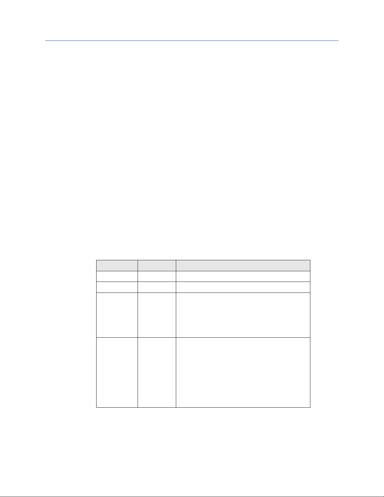
Security passwords
There are four role-based user accounts for the Gateway with varying levels of access.
Table 2-2 describes this access.
Table 2-2: Role Based Access User Accounts
Role User name Web Interface Access
Executive exec Read-only access
Operator oper Read-only access
Maintenance maint Configure HART® device settings
Configure Modbus communications
Configure Modbus register mapping
Configure OPC browse tree
Configure Active Advertising
Administrator admin Includes all maintenance privileges
Configure Ethernet network settings
Configure WirelessHART® network settings
Set passwords
Set time settings
Set home page options
Configure custom point pages
Restart applications
Each of the initial passwords for the user accounts is default. It is recommended, for
security purposes, that these passwords are changed. The administrator password should
be appropriately noted when changed. If it is lost, do not return the Gateway to the
factory, see Resetting to factory defaults.
10 Emerson.com/Rosemount

Reference Manual Configuration
00809-0200-4410 September 2020
To change the User Accounts Passwords:
Procedure
1. Navigate to System Settings → Users → User accounts.
2. Set the new password for each role based user account, and confirm.
3. Select Submit.
Note
It is suggested that the default security settings in System Settings → Users → User
Options be changed to the local IT best practices or the “Normal” setting after
initial login. Strong or custom settings are available for more robust passwords. For
more information on this screen and others see the User Interface Terminology
Guide (document number 00809-0600-4420).
Antivirus
Antivirus and other software tools are not included in the Gateway firmware. These
software tools should be installed on any machine connected to the Gateway. Emerson
bundles the latest software patches into our standard Gateway firmware updates. These
software patches are not anti-malware or anti-virus tools in any sense of the word, but do
provide the latest in security protection.
Password complexity
The browser front-end of the Gateway supports many customizable password rules
(System Settings → Users → User Options). All of the following rules are customizable:
• Minimum overall password length
• Minimum lowercase character count
• Minimum uppercase character count
• Minimum digit count
• Minimum symbol count
• Idle session timeout time
• Maximum session lifetime to force a user to re-enter their password
• Minimum password lifetime to prevent a user from changing their password too often
• Maximum password lifetime to periodically force a user to change their password.
• Password failure limit at which point the account is locked and the user must wait for a
specified period of time prior to additional attempts to enter their password
• Password failure lock to lock an account after a specified number of incorrect
passwords
• Require a wait period after the specified number of incorrect passwords have been
entered
• Password history depth to limit reuse of passwords
Emerson.com/Rosemount 11

Configuration Reference Manual
September 2020 00809-0200-4410
Logging
The Gateway monitors many security events automatically. A complete list of events can
be viewed from the Log Settings (System Settings → Gateway → Logging) area in the
Gateway interface. The Gateway also supports the optional use of a Syslog server. This
provides significant flexibility and allows the user to determine how log messages are
handled and how long logs are kept. It is possible for the user to configure the Syslog
server to issue automated alerts for various messages.
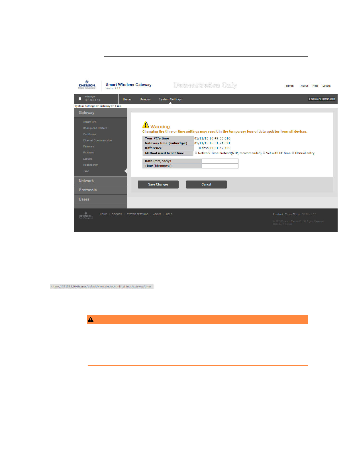
Time settings
The Gateway is the timekeeper for the WirelessHART network, so it is imperative that the
Gateway’s time is accurate for timestamp data to be meaningful. Time settings can be
found by navigating to System Settings → Gateway → Time as shown in Figure 2-2.
Gateway time settings and time stamps are stored internally as UTC time. The appropriate
web browser being used displays the time as per the local browser settings.
There are three ways to set the Gateway time:
Procedure
1. Network Time Protocol (recommended). This option uses a Network Time Protocol
(NTP) server to slowly adjust the Gateway’s time in order to match the time of the
control network. Enter the IP address for the NTP server and select the packet
version (1, 2, 3, or 4).
2. Set with PC Time. This option will match the Gateway’s time to that of the PC/
Laptop.
3. Manual Entry. This option allows the user to enter a specific date (MM:DD:YY) and
time (HH:MM:SS).
Note
Network Time Protocol (NTP) is recommended for the best network performance
because it always adjusts time to match the network time server.
Failure to provide regular time synchronization over a long period of time (months)
can cause the Gateway network to drift off time.
12 Emerson.com/Rosemount
Reference Manual Configuration
00809-0200-4410 September 2020
Figure 2-2: Setup → Time Settings
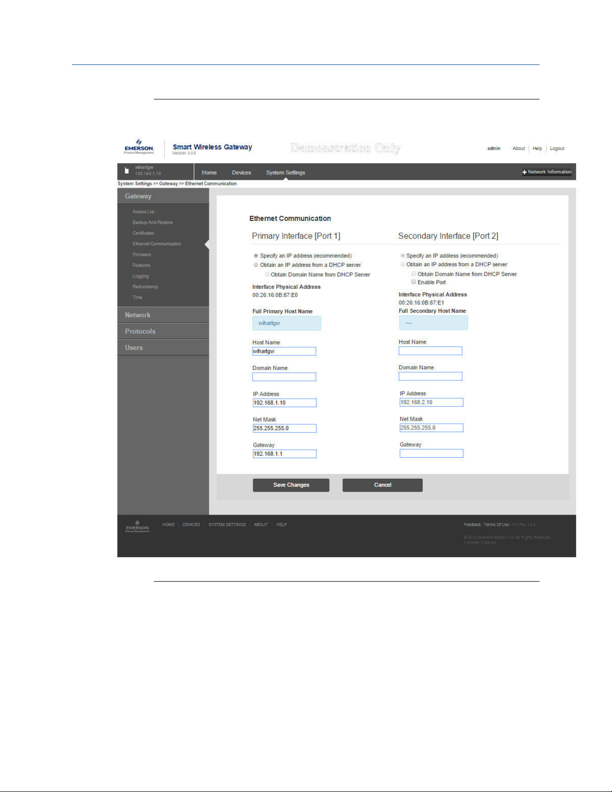
TCP/IP network settings
WARNING
Use caution when making changes to the TCP/IP network settings. If they are lost or
entered incorrectly, the Gateway will require a factory reset (see Resetting to factory
defaults). Contact the network administrator for information on the proper TCP/IP
network settings to apply.
Prior to the Gateway being installed and connected to a live control network, it should be
configured with an IP address, as well as other TCP/IP network settings. This specific page
can be found in System backup.
Emerson.com/Rosemount 13
Configuration Reference Manual
September 2020 00809-0200-4410
Figure 2-3: Ethernet Settings
Request the following configuration items from the network administrator:
• Hostname
• Domain Name
• IP address
• Netmask
• Gateway
14 Emerson.com/Rosemount

Reference Manual Configuration
00809-0200-4410 September 2020
Obtaining an IP address from a DHCP server is not recommended, since the Gateway
operation will be dependent on the availability of the DHCP server. For maximum Gateway
availability it is best practice to specify an IP address.
To change the TCP/IP Network Settings:
Procedure
1. Navigate to System Settings → Ethernet Communication.
2. Select Specify an IP address (recommended).
3. Enter the following:
• Hostname
• Domain Name
• IP Address
• Netmask
• Gateway
4. Select Submit.
5. When prompted, select Restart Apps.
6. Select Yes to confirm restart.
7. Close the web browser.
2.3.4
Note
Once the IP Address of the Gateway has been changed, communications to the web
interface will be lost. Restart the web browser, then log back into the Gateway using
the new IP address and other TCP/IP network settings. The PC/Laptop TCP/IP
network settings may need to be changed. During a Restart Apps the wireless
network will be temporarily lost.
System backup
The Gateway has a System Backup and Restore feature that saves all user-configured data.
It is best practice that a System Backup be performed periodically throughout the
installation and configuration process.
Procedure
1. Navigate to System Settings → Gateway → Backup and Restore → Save.
2. Select Save Configuration.
3. The Gateway collects the configuration date and when the file download pop up
appears, select Save.
4. Enter a save location and file name.
5. Select Save.
6. Select Return to form.
Emerson.com/Rosemount 15

Configuration Reference Manual
September 2020 00809-0200-4410
Note
System backup contains user passwords and keys used for encrypting
communication. Store downloaded system backups in a secure location.
2.3.5 Web page usage
It is not recommended that users stay logged on to a single page or a large number of
users on multiple pages for long periods of time. This additional loading can slow the flow
of data. The Gateway by default logs users out who are logged on for long periods of time
with no activity.
2.3.6 Resetting to factory defaults
In the event that the user name, password, or IP address of the Gateway is lost, the
Gateway can be restored to factory defaults by the procedure below.
Note
Following this procedure will cause the network to reform and all configuration
parameters will be reset to factory defaults. Once the Gateway is reset, the user is strongly
recommended to change the default password to maintain system security.
Procedure
1. Turn off power to the Gateway, remove connectors, and un-mount the device from
the DIN rail.
2. Locate the Reset switch label on the back of the Gateway.
3. Break the label in the center and slide the switch up.
4. Mount and reconnect the Gateway; turn power ON on to the gateway.
5. Let the Gateway completely boot up (approximately 2 minutes). During this time
the red Reset light on the front of the unit will be ON.
6. Turn off power to the Gateway, remove connectors and un-mount it from the rail
again.
7. Return the Reset switch to lower position.
8. Mount and reconnect the Gateway; turn power ON on to the Gateway.
9. Verify the reset light is off, indicating the Reset switch is in the lower position. The
Gateway will now be programmed back to factory defaults including IP addresses.
The factory default IP addresses can be found in Table 2-1.
16 Emerson.com/Rosemount

Reference Manual Installation
00809-0200-4410 September 2020
3 Installation
3.1 Overview
This section describes how to properly mount the Emerson Smart Wireless Gateway 1410
and make electrical connections, including electrical wiring, grounding, and host system
connections. This section also describes how to mount the optional remote antenna.
3.1.1 General considerations
The unit itself is not designed for outdoor mounting without a suitable enclosure. The
Gateway should be mounted in an approved electrical enclosure or building.
The Gateway should be mounted in a location that allows convenient access to the host
system network (process control network) as well as the wireless field device network and
protects the Gateway from moisture and contamination.
3.1.2
Physical description
The Gateway electronics is enclosed in a polymer housing. The front of the enclosure has
connections for power, Ethernet, and serial communications. The unit is designed to be
mounted on a DIN rail inside an electronic enclosure.
3.2 Mounting
The unit can be snapped onto a DIN TS35/7.5 or TS35/15 rail system. To clip the unit onto
the DIN rail, see Figure 3-1.
Procedure
1. Tilt the unit at a slight angle allowing the lower lip of the chassis to catch the
bottom of the DIN rail.
2. Apply pressure forward to snap the back of the unit securely onto the DIN rail.
Emerson.com/Rosemount 17

Installation Reference Manual
September 2020 00809-0200-4410
Figure 3-1: Installing
To remove the unit, see Figure 3-2.
3. Place a flat or rounded object (such as a screw driver) into the DIN clip and apply a
slight pressure downwards on the object.
4. Once the unit is released from the DIN rail pull backwards and down to successfully
disengage.
Figure 3-2: Removing
18 Emerson.com/Rosemount

Reference Manual
00809-0200-4410 September 2020
Installation
NOTICE
When mounting the unit in an electrical enclosure or other location, comply with
the appropriate local and governmental installation codes. Verify the installer,
associated hardware, and installation equipment used have the proper
certifications for the specific type of installation being performed. Before
installation, verify if local codes require a permit and/or an inspection before
energizing. When planning the installation, account for routing the antenna cable
within the enclosure.
Note
Do not mount the antenna within a metal enclosure. To avoid damage to sensitive
RF components, do not remove protective cap from the Gateway SMA connector
until ready to install the antenna.
3.3 Remote antenna
The small black flexible basic antenna supplied with the unit is for bench testing. In most
locations, a remote antenna is recommended for best range and performance. The
remote antenna options provide flexibility for mounting the Gateway based on wireless
connectivity, lightning protection, and current work practices.
Note
To avoid damage to sensitive RF components do not remove protective cap from the
Gateway SMA connector until ready to install the antenna.
WARNING
When installing remote mount antennas for the Wireless Gateway, always use established
safety procedures to avoid falling or contact with high-power electrical lines.
Install remote antenna components for the Wireless Gateway in compliance with local and
national electrical codes and use best practices for lightning protection.
Before installing consult with the local area electrical inspector, electrical officer, and work
area supervisor.
The Wireless Gateway remote antenna option is specifically engineered to provide
installation flexibility while optimizing wireless performance and local spectrum approvals.
To maintain wireless performance and avoid non-compliance with spectrum regulations,
do not change the length of cable or the antenna type.
If the supplied remote mount antenna kit is not installed per these instructions, Emerson is
not responsible for wireless performance or non-compliance with spectrum regulations.
The remote antenna kit includes coaxial sealant for the cable connections, for the
lightning arrestor, and for the antenna.
Find a location where the remote antenna has optimal wireless performance. Ideally this
will be 15- to 25-ft. (4,6 to 7,6 m) above the ground or 6-ft. (2 m) above obstructions or
major infrastructure. To install the remote antenna use one of the following procedures:
Emerson.com/Rosemount 19

C
D
E
F
G
A
B
Installation
Reference Manual
September 2020 00809-0200-4410
3.3.1 Installation of WL2/WN2 option
Procedure
1. Mount the antenna on a 1.5- to 2-in. pipe mast using the supplied mounting
equipment.
2. Connect the lightning arrestor directly to the bottom of the user supplied
enclosure.
3. Install the grounding lug, lock washer, and nut on top of the lightning arrestor.
4. Connect the antenna to the lightning arrestor using the supplied coaxial cable
ensuring the drip loop is not closer than 1-ft. (0,3 m) from the lightning arrestor.
5. Use the coaxial sealant to seal each connection between the Gateway, lightning
arrestor, cable, and antenna.
6. Ensure that the mounting mast, lightning arrestor, and Gateway are grounded
according to local/national electrical code.
Any spare lengths of coaxial cable should be placed in 1-ft. (0,3 m) coils.
Figure 3-3: Installation of WL2/WN2 Option
A. User supplied enclosure containing Gateway
B. Ground
C. Remote antenna
D. Cable
E. Lightning arrestor
F. Drip loop
G. Earth
20 Emerson.com/Rosemount

Reference Manual
00809-0200-4410 September 2020
Note
Weather proofing is required! The remote mount antenna kit includes coaxial
sealant for the cable connections for the lightning arrestor, antenna, and Gateway.
The coaxial sealant must be applied to guarantee performance of the wireless field
network. See Figure 3-4 for details on how to apply weather proofing.
Figure 3-4: Applying Coaxial Sealant to Cable Connections
Table 3-1: Remote Antenna Kit Options
Kit option Antenna Cable 1 Lightning arrestor
Installation
WL2 1/2 Wavelength Dipole
WN2 1/2 Wavelength Dipole
3.4 Connections
3.4.1 Grounding
The DIN rail should always be grounded in accordance with national and local electrical
codes. The most effective grounding method is a direct connection to earth ground with
minimal impedance. Grounding to the Gateway is accomplished through the DIN rail clip
on the back of the Gateway.
3.4.2
Ethernet
The Gateway is equipped with two 10/100 base-TX Ethernet communications ports (see
Figure 3-5). These connections can be used to access the Gateway’s web interface and to
communicate Modbus® TCP, OPC, and EtherNet/IP™ protocols.
Omni-Directional +6 dB
Gain
Omni-Directional +8 dB
Gain
50 ft. (15,2 m) LMR-400 Head mount, jack to plug
Gas discharge tube
0.5 dB insertion loss
25 ft. (7,6 m) LMR-400 Head mount, jack to plug
Gas discharge tube
0.5 dB insertion loss
The primary Ethernet port (Ethernet 1) is used to connect to the host system or other
application systems. The secondary Ethernet port (Ethernet 2) can be used as a back up
connection or a maintenance port for local access to the Gateway.
Note
Unless dual Ethernet ports were specified at the time of order, the secondary Ethernet port
(Ethernet 2) will not be active.
Emerson.com/Rosemount 21
 Loading...