

Rosemount Manual: CAT 7 Thermal Conductivity Transmitter-Rev B | Rosemount Manuals & Guides

Instruction Manual
748451-B
March 2002
Model CAT7
Thermal Conductivity Analyzer
http://www.processanalytic.com

ESSENTIAL INSTRUCTIONS
READ THIS PAGE BEFORE PROCEEDING!
Rosemount Analytical designs, manufactures and tests its products to meet many national and
international standards. Because these instruments are sophisticated technical products, you
MUST properly install, use, and maintain them to ensure they continue to operate within their
normal specifications. The following instructions MUST be adhered to and integrated into your
safety program when installing, using, and maintaining Rosemount Analytical products. Failure to
follow the proper instructions may cause any one of the following situations to occur: Loss of life;
personal injury; property damage; damage to this instrument; and warranty invalidation.
• Read all instructions prior to installing, operating, and servicing the product.
• If you do not understand any of the instructions, contact your Rosemount Analytical repre-
sentative for clarification.
• Follow all warnings, cautions, and instructions marked on and supplied with the product.
• Inform and educate your personnel in the proper installation, operation, and mainte-
nance of the product.
• Install your equipment as specified in the Installation Instructions of the appropriate In-
struction Manual and per applicable local and national codes. Connect all products to the
proper electrical and pressure sources.
• To ensure proper performance, use qualified personnel to install, operate, update, program,
and maintain the product.
• When replacement parts are required, ensure that qualified people use replacement parts
specified by Rosemount. Unauthorized parts and procedures can affect the product’s performance, place the safe operation of your process at risk, and VOID YOUR WARRANTY.
Look-alike substitutions may result in fire, electrical hazards, or improper operation.
• Ensure that all equipment doors are closed and protective covers are in place, except
when maintenance is being performed by qualified persons, to prevent electrical shock
and personal injury.
The information contained in this document is subject to change without notice.
Teflon® is a registered trademark of E.I. duPont de Nemours and Co., Inc.
SNOOP® is a registered trademark of NUPRO Co.
Emerson Process Management
Rosemount Analytical Inc.
Process Analytic Division
1201 N. Main St.
Orrville, OH 44667-0901
T (330) 682-9010
F (330) 684-4434
e-mail: gas.csc@EmersonProcess.com
http://www.processanalytic.com

Model CAT7
PREFACE...........................................................................................................................................1
Definitions ...........................................................................................................................................1
safety Summary..................................................................................................................................2
General Precautions For Handling And Storing High Pressure Gas Cylinders .................................4
Documentation....................................................................................................................................5
Compliances .......................................................................................................................................5
1.0 DESCRIPTION AND SPECIFICATIONS..............................................................................1-1
1-1 Analyzer Module....................................................................................................................1-1
1-2 Thermal Conductivity Cell......................................................................................................1-1
1-3 Electronic Circuitry.................................................................................................................1-4
1-4 Gas Selector Panel................................................................................................................1-4
1-5 Specifications ........................................................................................................................1-5
Instruction Manual
748451-B
March 2002
TABLE OF CONTENTS
2.0 INSTALLATION ....................................................................................................................2-1
2-1 Site Preparation.....................................................................................................................2-1
2-2 Customer Electrical Connections ..........................................................................................2-1
2-3 Flow Diagrams.......................................................................................................................2-1
2-4 Location and Mounting ..........................................................................................................2-1
a. Location...........................................................................................................................2-1
b. Mounting .........................................................................................................................2-1
2-5 Unpacking..............................................................................................................................2-3
2-6 Gas Requirements.................................................................................................................2-3
2-7 Calibration Gas Requirements ..............................................................................................2-3
a. Sample Gas Composition ...............................................................................................2-3
2-8 Suppressed-Zero Ranges .....................................................................................................2-3
2-9 Leak Check............................................................................................................................2-3
2-10 Gas Connections ...................................................................................................................2-4
2-11 Recorder Output Selection and Cable Connections .............................................................2-8
a. Standard (Non-linearized) Voltage Output......................................................................2-8
b. Linearized Voltage Output (Optional)..............................................................................2-8
c. Isolated 4 to 20 mA Current Output (Optional) ...............................................................2-8
2-12 Alarms (Optional)...................................................................................................................2-10
2-13 Linearized Voltage, Two Ranges (Optional)..........................................................................2-12
2-14 Linearized Voltage and Isolated 4 to 20 mA Current Output (Optional)................................2-12
2-15 Electrical Power Connections................................................................................................2-13
3.0 OPERATION .........................................................................................................................3-1
3-1 Analyzer Controls and Adjustments ......................................................................................3-1
3-2 Gas Selector Panel Controls .................................................................................................3-1
3-3 Startup Procedure .................................................................................................................3-1
3-4 Calibration..............................................................................................................................3-2
Rosemount Analytical Inc. A Division of Emerson Process Management Contents i

Instruction Manual
748451-B
March 2002
4.0 THEORY................................................................................................................................4-1
4-1 Thermal Conductivity Cell and Associated Bridge Adjustments ...........................................4-1
4-2 Master Board .........................................................................................................................4-1
a. Functions Associated with AR1 ......................................................................................4-1
b. Coarse zero and zero-suppression.................................................................................4-2
c. Functions Associated with AR2 ......................................................................................4-2
d. Meter ...............................................................................................................................4-2
e. Output Selection Switch S1 ............................................................................................4-2
4-3 Voltage Output Linearizer Board Option ...............................................................................4-2
4-4 Isolated 4 to 20 mA Current Output Board Option ................................................................4-4
4-5 Bridge Power Supply .............................................................................................................4-4
4-6 ±15 Volt Power Supply ..........................................................................................................4-4
4-7 Detector Blocks .....................................................................................................................4-4
4-8 Case Temperature Controller Assembly ...............................................................................4-4
4-9 Dual Alarms Option ...............................................................................................................4-5
5.0 SERVICE AND MAINTENANCE ..........................................................................................5-1
5-1 Thermal Conductivity Cell......................................................................................................5-1
5-2 Electronic Circuitry.................................................................................................................5-4
a. Amplifier Zero Adjustments.............................................................................................5-4
b. Bridge Balance and Range Sensitivity Adjustments.......................................................5-4
c. Case Temperature Controller .........................................................................................5-5
d. Dual Alarm Module (Optional).........................................................................................5-5
5-3 Suppressed Zero Adjustment................................................................................................5-5
Model CAT7
6.0 REPLACEMENT PARTS ......................................................................................................6-1
6-1 Matrix .....................................................................................................................................6-1
6-2 Circuit Board Replacement Policy .........................................................................................6-3
6-3 Replacement Parts ................................................................................................................6-4
7.0 RETURN OF MATERIAL ......................................................................................................7-1
7-1 Return Of Material .................................................................................................................7-1
7-2 Customer Service ..................................................................................................................7-1
7-3 Training..................................................................................................................................7-1
ii Contents Rosemount Analytical Inc. A Division of Emerson Process Management

Model CAT7
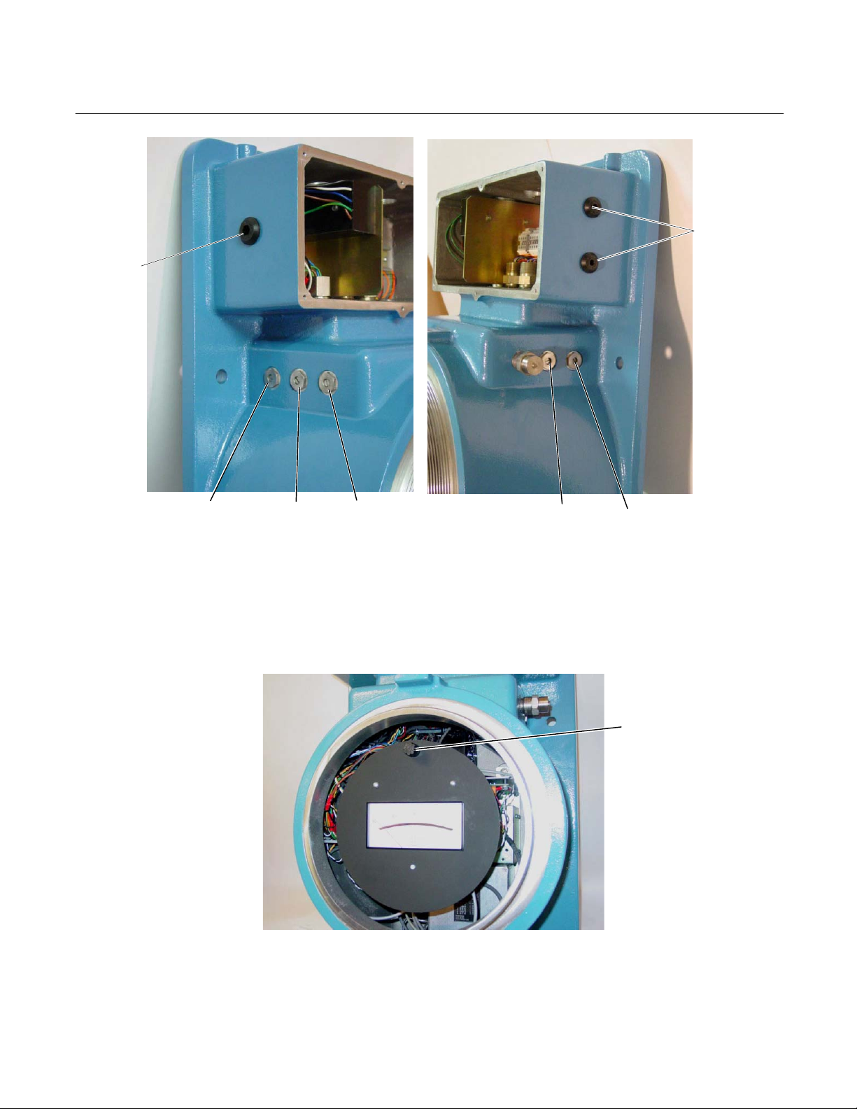
Figure 1-1. CAT7 Controls, Adjustments, Ports .......................................................................... 1-2
Figure 1-2. Fuse Location............................................................................................................ 1-2
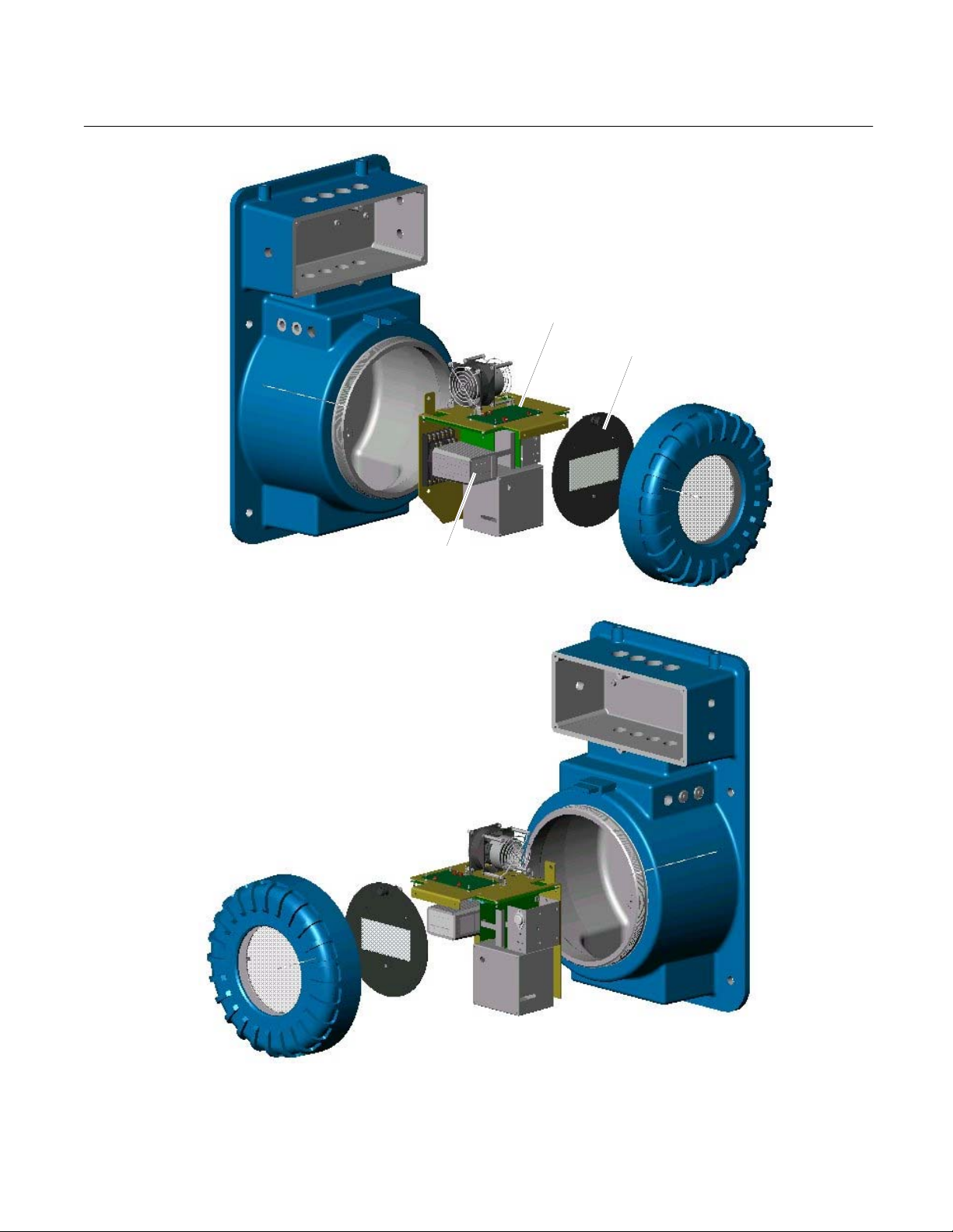
Figure 1-3. CAT7 – Exploded View ............................................................................................. 1-3
Figure 1-4. Typical Gas Selector Panel....................................................................................... 1-4
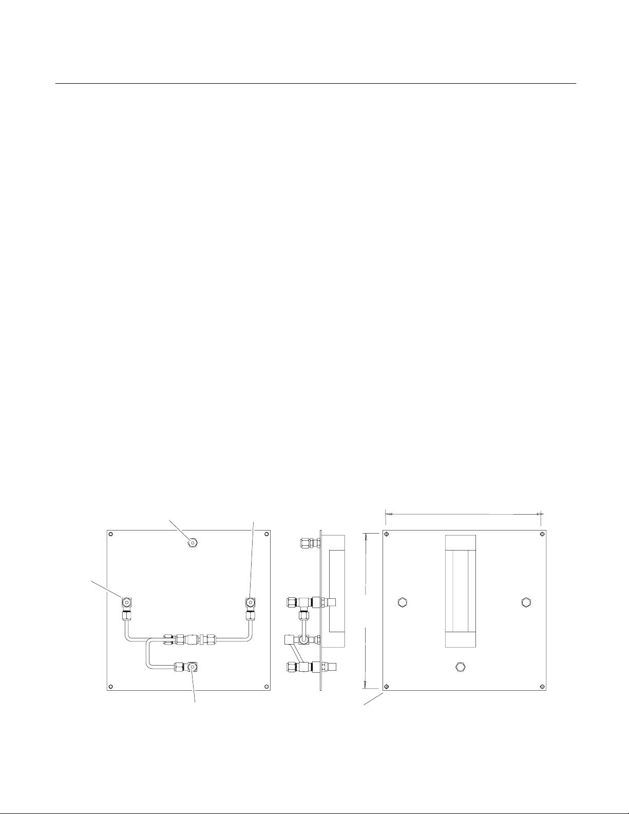
Figure 2-1. Gas Selector Panel for Thermal Conductivity Cell with Sealed-In Reference Gas .. 2-1
Figure 2-2. Gas Selector Panel for Thermal Conductivity Cell Using Flowing Reference Gas .. 2-2
Figure 2-3. Gas Connections – Bottom View of Analyzer ........................................................... 2-4
Figure 2-4. Connection of Analyzer Using Sealed-In Reference Gas to Associated Gas .......... 2-5
Figure 2-5. Connection of Analyzer Using Flowing Reference Gas to Associated Gas Selector
Figure 2-6. Intrinsic Safety Box ................................................................................................... 2-7
Figure 2-7. Intrinsic Safety Box Interconnect .............................................................................. 2-7
Figure 2-8. Master Board............................................................................................................. 2-9
Figure 2-9. Alarm Adjustments ..................................................................................................2-10
Figure 2-10. Typical Alarm Settings .......................................................................................... 2-11
Figure 2-11. Case Heater Temperature Control Board............................................................. 2-13
Figure 4-1. Thermal Conductivity Cell ......................................................................................... 4-3
Instruction Manual
748451-B
March 2002
LIST OF ILLUSTRATIONS
Panel...................................................................................................................... 2-6
LIST OF TABLES
Table 1-1. Available Gas Selector Panels................................................................................... 1-5
Table 4-1. Range Switch Connections ........................................................................................ 4-2
DRAWINGS
613561 Schematic Diagram, Bridge Power Supply - Regulated 5 to 15V
619710 Schematic Diagram, 15V Power Supply
624003 Schematic Diagram, Temperature Controller
652813 Schematic Diagram, Isolated Current Output
652863 Schematic Diagram, Linearizer Board
654616 Schematic Diagram, Master Board
661200 Assembly Instructions, CAT7
661203 Assembly, Chassis
661318 Installation Drawing, CAT7
661540 Assembly, Temperature Control
661541 Assembly, Meter
661562 Wiring Diagram, CAT7
(LOCATED IN REAR OF MANUAL)
Rosemount Analytical Inc. A Division of Emerson Process Management Contents iii

Instruction Manual
748451-B
March 2002
Model CAT7
iv Contents Rosemount Analytical Inc. A Division of Emerson Process Management

Instruction Manual
Model CAT7
PREFACE
The purpose of this manual is to provide information concerning the components,
functions, installation and maintenance of the CAT7 Thermal Conductivity Analyzer.
Some sections may describe equipment not used in your configuration. The user should
become thoroughly familiar with the operation of this module before operating it. Read
this instruction manual completely.
DEFINITIONS
The following definitions apply to DANGERS, WARNINGS, CAUTIONS and NOTES found throughout
this publication.
DANGER .
748451-B
March 2002
Highlights the presence of a hazard which will cause severe personal injury, death, or substantial
property damage if the warning is ignored.
WARNING .
Highlights an operation or maintenance procedure, practice, condition, statement, etc. If not
strictly observed, could result in injury, death, or long-term health hazards of personnel.
CAUTION.
Highlights an operation or maintenance procedure, practice, condition, statement, etc. If not
strictly observed, could result in damage to or destruction of equipment, or loss of effectiveness.
NOTE
Highlights an essential operating procedure,
condition or statement.
Rosemount Analytical Inc. A Division of Emerson Process Management Preface P-1

Instruction Manual
748451-B
March 2002
Model CAT7
SAFETY SUMMARY
To avoid explosion, loss of life, personal injury and damage to this equipment and on-site property, all personnel authorized to install, operate and service the Model CAT7 Thermal Conductivity Analyzer should be
thoroughly familiar with and strictly follow the instructions in this manual. Save these instructions.
If this equipment is used in a manner not specified in these instructions, protective systems may be
impaired.
AUTHORIZED PERSONNEL
To avoid explosion, loss of life, personal injury and damage to this equipment and on-site
property, all personnel authorized to install, operate and service the this equipment should be
thoroughly familiar with and strictly follow the instructions in this manual. SAVE THESE INSTRUCTIONS.
DANGER.
ELECTRICAL SHOCK HAZARD
Do not operate without doors and covers secure. Servicing requires access to live parts which can
cause death or serious injury. Refer servicing to qualified personnel.
For safety and proper performance this instrument must be connected to a properly grounded
three-wire source of power.
NOTE
Before supplying electrical power to the analyzer, remove power to the bridge by disconnecting the
red lead from the bridge to TB1-1 or TB1-2 (depending on the bridge polarity). See drawing 661562.
To safeguard against filament damage, this lead should remain disconnected until proper gas flow
has been established.
DANGER
EXPLOSION HAZARD
Do not operate the Model CAT7 Explosion-Proof Analyzer without the lens cover in place and completely secured, unless location have been determined to be non-hazardous.
P-2 Preface Rosemount Analytical Inc. A Division of Emerson Process Management

Instruction Manual
Model CAT7
DANGER
EXPLOSION HAZARD
This analyzer is of a type capable of analysis of sample gases which may be flammable. If used for
analysis of such gases, the instruments explosion-proof enclosure must be suitable for the gas.
If explosive gases are introduced into this analyzer, the sample containment system must be carefully leak-checked upon installation and before initial startup, during routine maintenance and any
time the integrity of the sample containment system is broken, to ensure the system is in leak-proof
condition. Leak-check instructions are provided in Section 2-9.
Internal leaks resulting from failure to observe these precautions could result in an explosion
causing death, personal injury or property damage.
WARNING .
PARTS INTEGRITY
Tampering or unauthorized substitution of components may adversely affect safety of this product.
Use only factory documented components for repair.
748451-B
March 2002
WARNING.
HIGH PRESSURE GAS CYLINDERS
This instrument requires periodic calibration with a known standard gas. See also General Precautions for Handling and Storing High Pressure Gas Cylinders, page P-4.
Rosemount Analytical Inc. A Division of Emerson Process Management Preface P-3

Instruction Manual
748451-B
March 2002
Model CAT7
GENERAL PRECAUTIONS FOR HANDLING AND STORING HIGH
PRESSURE GAS CYLINDERS
Edited from selected paragraphs of the Compressed Gas Association's "Handbook of Compressed
Gases" published in 1981
Compressed Gas Association
1235 Jefferson Davis Highway
Arlington, Virginia 22202
Used by Permission
1. Never drop cylinders or permit them to strike each other violently.
2. Cylinders may be stored in the open, but in such cases, should be protected against extremes of weather
and, to prevent rusting, from the dampness of the ground. Cylinders should be stored in the shade when located in areas where extreme temperatures are prevalent.
3. The valve protection cap should be left on each cylinder until it has been secured against a wall or bench, or
placed in a cylinder stand, and is ready to be used.
4. Avoid dragging, rolling, or sliding cylinders, even for a short distance; they should be moved by using a suitable hand-truck.
5. Never tamper with safety devices in valves or cylinders.
6. Do not store full and empty cylinders together. Serious suckback can occur when an empty cylinder is attached to a pressurized system.
7. No part of cylinder should be subjected to a temperature higher than 125
permitted to come in contact with any part of a compressed gas cylinder.
8. Do not place cylinders where they may become part of an electric circuit. When electric arc welding, precautions must be taken to prevent striking an arc against the cylinder.
°
F (52°C). A flame should never be
P-4 Preface Rosemount Analytical Inc. A Division of Emerson Process Management

Instruction Manual
Model CAT7
DOCUMENTATION
The following CAT7 Thermal Conductivity Analyzer instruction materials are available. Contact Customer
Service or the local representative to order.
748451 Instruction Manual (this document)
COMPLIANCES
This product may carry approvals from several certifying agencies. The certification marks appear on the
product name-rating plate.
Area Classifications:
USA
Class I Zone 1
AEx d e m IIB + H
2
T4
748451-B
March 2002
Canada
Ex d e m IIB + H
European Union
ATEX, Category 2, Zone 1, IIB + H
USA/Canada
Certified by Canadian Standards Association, an OSHA Nationally Recognized Testing Laboratory (NRTL) for USA and Canada.
European Union
Conforms with the provisions of the EMC Directive 89/336/EEC, Low Voltage Directive 73/23/EEC, Potentially Explosive Atmospheres Directive
94/9/EC, including amendments by the CE marking Directive 93/68/EEC.
EC type Examination Certificate, LCIE 00 ATEX 6009 X.
Rosemount Analytical has satisfied all obligations from the European Legislation to harmonize the product requirements in Europe.
Australia/New Zealand
T4
2
T4
2
®
0081
EEx d e m II B (+H2) T4
LCIE 00 ATEX 6009 X
II 2 G
Conforms with Electromagnetic Compatibility – Generic Emission standard
and AS/NZS 4251.1 – 1994 Part 1 – Residential, commercial, and light industrial.
Complies with the NAMUR RECOMMENDATION, Electromagnetic Compatibility (EMC) issue 1998.
Rosemount Analytical Inc. A Division of Emerson Process Management Preface P-5
NAMUR
N96

Instruction Manual
748451-B
March 2002
Model CAT7
P-6 Preface Rosemount Analytical Inc. A Division of Emerson Process Management

Model CAT7
Instruction Manual
748451-B
March 2002
SECTION 1
DESCRIPTION AND SPECIFICATIONS
The Model CAT7 Thermal Conductivity Analyzer is
designed to continuously measure the concentration of
a single component of interest in a flowing gas mixture. The measurement is based on the different
thermal conductivity's of the individual components of
the sample stream. The method is especially well
suited to analysis of two-component sample streams.
However, analysis of multi-component streams is possible if the various components of the background gas
occur in relatively constant ratio, or have similar thermal conductivity's.
Each Model CAT7 Analyzer is factory-assembled, as
ordered, for determination of a specified component,
with specified range of concentration, contained in a
background component or background mixture of
known composition. Typical examples include: 0 to
100 % hydrogen in nitrogen; 20 to 50 % helium in
methane; and 0% to 3% carbon dioxide in air. If so
ordered, the instrument is provided with two or three
ranges; selectable via a side-panel switch. Information specific to the individual instrument is provided in
the data sheet inserted in the back of this instruction
manual.
A Model CAT7 Analyzer consists of an analyzer module, Section 1-1, and, if ordered, an accessory gas
selector panel, Section 1-4.
1-2 THERMAL CONDUCTIVITY CELL
The thermal conductivity cell is a metal
block with separate passages for the sample and reference gases. In all applications,
the sample passage receives a continuous
flow of sample gas. Depending on the application, the reference passage may receive a continuous flow of reference gas, or
may have the reference gas sealed within.
The sample passage contains a pair of
temperature-sensitive resistive filaments.
The reference passage contains a similar
pair. Electrically, the filaments are connected as legs of a Wheatstone bridge. An
internal voltage-regulated power supply is
connected via a 20-ohm dropping resistor,
to the bridge.
With the power supply output adjusted to
provide an appropriate voltage across the
bridge, an electric current flows through the
filaments, heating them and thus increasing
their electrical resistance. The
heat-dissipation rate for each filament depends on the thermal conductivity of the
surrounding gas.
1-1 ANALYZER MODULE
The analyzer module is supplied in an explosion-proof enclosure suitable for installation in
hazardous locations classified as Zone 1,
Groups II B (+H
Group II B (+H
Rosemount Analytical Inc. A Division of Emerson Process Management Description and Specifications 1-1
), T4, Category 2, Zone 1,
2
), T4.
2
Initially, with suitable downscale calibration
gas flowing through the sample passage
(and also through the reference passage if
of the flow-through configuration), the
bridge is balanced. Thereafter, any change
in the relative proportions of the components passing through the sample passage
changes the thermal conductivity of the gas
mixture, causing a temperature differential
between sample and reference filaments.
The resultant change in filament resistance
unbalances the bridge, applying a signal to
the electronic circuitry (Section 1-3).
Instruction Manual
Adj
748451-B
March 2002
AC Power
Port
Model CAT7
Signal Output,
Alarm Ports
Alarm
Alarm
Figure 1-1. CAT7 Controls, Adjustments, Ports
Range Select
Zero
ust
Span
Fuse
Figure 1-2. Fuse Location
1-2 Description and Specifications Rosemount Analytical Inc. A Division of Emerson Process Management
Model CAT7
Instruction Manual
748451-B
March 2002
Chassis Assembly
Meter Assembly
Alarm Module
Figure 1-3. CAT7 – Exploded View
Rosemount Analytical Inc. A Division of Emerson Process Management Description and Specifications 1-3

Instruction Manual
1
1
748451-B
March 2002
Model CAT7
1-3 ELECTRONIC CIRCUITRY
The analyzer module contains solid-state circuitry that conditions the bridge-imbalance
signal as required to provide readout on the
meter. In addition, a field-selectable output
for a voltage-type recorder is provided as
standard. A field-selectable output of 4 to 20
mA for a current-actuated recorder or other
device is obtainable through use of an optional plug-in circuit board. A calibration
curve can be used to convert meter or recorder readings into concentration values.
Typical calibration curves are supplied for
standard ranges. Calibration curves for special ranges are available as options.
To avoid use of a calibration curve in an application where it would otherwise be required,
the analyzer may be equipped with an optional linearizer board. If so, the linearizer is
factory set for a given range only, and is not
usable on another range. Note that a linearizer is usable only if non-linearity at mid-
scale does not exceed approximately 20% of
fullscale.
1-4 GAS SELECTOR PANEL
If so ordered, the analyzer module is provided
with an appropriate gas selector panel, Figure
1-4. The gas selector panel permits selection,
flow adjustment, and flow measurement for
the various gases: sample; flowing reference
gas, if used; and downscale and upscale calibration gases. Proper choice of a gas selector panel depends on:
1. Configuration of the thermal conductivity
cell, i.e., flowing or sealed-in reference
gas.
2. Composition of the sample stream. For
non-corrosive streams, the gas selector
panel is assembled with brass components. For corrosive streams, stainless
steel is used.
Reference Gas
Flow Meter
Downscale Calibration
Gas Needle Valve
DOWNSCALE
CAL GAS
UPSCA LE
CAL GAS
Upscale Calibration Gas
Needle Valve
1 Provided only if thermal conductivity cell uses flowing reference gas.
REF
SAMPLE
Figure 1-4. Typical Gas Selector Panel
Sample/Calibration
Gas Flow Meter
SAMPLE
REFERENCE
Sample Gas
Needle Valve
Reference Gas
Needle Valve
1-4 Description and Specifications Rosemount Analytical Inc. A Division of Emerson Process Management

Model CAT7
Brass and Copper construction for use with sealed reference 113357
Stainless steel construction for use with sealed reference 113920
Brass and Copper construction for use with flowing reference 117195
Stainless steel construction for use with flowing reference 118210
1-5 SPECIFICATIONS
Reproducibility............................... ±0.5% of fullscale
Zero Drift
Span Drift
Noise ............................................. Less than ±0.5% of fullscale
Cell Response Time
Sample Flow.................................. Nominal, 50 to 350 cc/min; recommended, 250 cc/min.
Calibration Gas Flow ..................... Nominal, 50 to 350 cc/min; recommended, 250 cc/min.
Reference Gas Flow (If Req’d)...... 5 to 50 cc/min.
Supply Pressure ............................ 10 to 50 psig (69 to 345 kPa)
Meter ............................................. Indicating analog meter is standard.
Operating Ranges ......................... Various zero-based and zero-suppressed ranges, from 0% to
Ambient Temperature Range........ 32°F to 100°F (0°C to 38°C). Case Temperature controlled at
Output Voltage
1
...................................... ±1% of fullscale per 24 hours
1
Non-Linearized (Standard) .... Switch selectable: 0 to 10 mV, 0 to 100 mV, 0 to 1V or 0 to 5V DC
Linearized (Option) ................ Switch selectable: 0 to 10 mV, 0 to 100 mV, 0 to 1V or 0 to 5V DC
DESCRIPTION PART NUMBER
Table 1-1. Available Gas Selector Panels
..................................... ±1% of fullscale per 24 hours
2
..................... 30 seconds for 95% response, with sample flow of 250 cc/min.
100%, are available. Single range is standard; switch-selectable
dual or triple range is optional.
117°F (47°C).
Instruction Manual
748451-B
March 2002
Isolated Current Output (Option)... 4 to 20 mA, maximum load 1500 ohms
Dual Alarms (Option)..................... Relay contact rating: 1.0 A, 120V AC; 5.0 A, 120V DC, resistive
loads
Cell Materials (Standard Cell) ....... 316 stainless steel block with tungsten or Hitempco filaments. Cor-
rosion-resistant filaments available on order
Power Requirements..................... 115/230 VAC ±10%, 50/60 Hz, 250 Watts
Enclosure....................................... Zone 1, Groups II B (+H
(+H
), T4
2
1
Zero and Span drift specifications based on ambient temperature shifts of less than 18 Fahrenheit degrees (10 Celsius de-
grees) at a maximum rate of 18 Fahrenheit degrees (11 Celsius degrees) per hour.
2
Cell response time is less than 45 seconds for 95% response, with sample flow rate of 250 cc/min, for the following gas
combinations: Argon and air, nitrogen, or oxygen; carbon dioxide and argon, nitrogen, or oxygen; helium and methane; hydrogen and methane.
Rosemount Analytical Inc. A Division of Emerson Process Management Description and Specifications 1-5
), T4, Category 2, Zone 1, Group II B
2

Instruction Manual
748451-B
March 2002
Model CAT7
1-6 Description and Specifications Rosemount Analytical Inc. A Division of Emerson Process Management
Model CAT7
Instruction Manual
748451-B
March 2002
SECTION 2
INSTALLATION
2-1 SITE PREPARATION
This section provides information that may be
required prior to installation.
For outline and mounting dimensions of the
analyzer drawing 661318. For outline and
mounting dimensions of the gas selector
panel, see Figure 2-1, and Figure 2-2.
2-2 CUSTOMER ELECTRICAL CONNECTIONS
Customer electrical connections are shown in
Figure 2-7 and drawing 661562.
2-3 FLOW DIAGRAMS
For gas connections, refer to appropriate flow
diagram:
• Analyzer using sealed reference
gas, Figure 2-4.
• Analyzer using flowing reference
gas, Figure 2-5.
2-4 LOCATION AND MOUNTING
a. Location
Proper location for the analyzer depends
on two basic considerations:
•
Accessibility to the sampling point
•
Protection of the instrument
Ideally, the analyzer should be located as
close to the sampling point as possible.
Short sample lines reduce time lag in
readings. In practice, however, protection
of the instrument sometimes calls for
more remote placement.
The analyzer should be mounted in a
clean, dry atmosphere. Ambient temperature should be within the range of
o
32
F to 100 F (0oC to 38oC).
b. Mounting
The analyzer is designed for wall mounting. Refer to drawing 661318.
10.25
[260]
SAMPLE
Span Gas In
To Analyzer
Sample In
Zero Gas In
8.25
[210]
Mounting Holes (4)
NO. 8 Flat Head Screw
ZERO SPAN
Figure 2-1. Gas Selector Panel for Thermal Conductivity Cell with Sealed-In Reference Gas
Rosemount Analytical Inc. A Division of Emerson Process Management Installation 2-1

Instruction Manual
748451-B
March 2002
Model CAT7
Sample Gas
To Analyzer
Sample Inlet
To Analyzer
Ref Gas Inlet
Downscale Calibration Gas
1.25
[32]
DOWNSCALE
CALIBRATION GAS
10.25
[260]
8.25
[210]
REF SAMPLE
UPSCALE
CALIBRATION GAS
3.25
[83]
.12
[3]
Mounting Holes (4)
NO. 8 Flat Head Screw
Ref Gas
Upscale Calibration Gas
Figure 2-2. Gas Selector Panel for Thermal Conductivity Cell Using Flowing Reference Gas
SAMPLE
REF
2-2 Installation Rosemount Analytical Inc. A Division of Emerson Process Management
 Loading...