


Rosemount Analytical
M
ODEL
C
ONTINUOUS ANALYZER
T
RANSMITTER
O
PERATION AND MAINTENANCE
CAT 200
M
ANUAL
748446-C

OTICE
N
The information contained in this document is subject to change without notice.
This manual is based on the production version of the Model CAT 200 Continuous Analyzer
Transmitter. Hardware and/or software changes may have occurred since this printing.
Teflon® is a registered trademark of E. I. duPont de Nemours and Co., Inc.
SNOOP® is a registered trademark of NUPRO Co.
Manual Part Number 748446-C
March 2001
Printed in U.S.A.
Rosemount Analytical Inc.
4125 East La Palma Avenue
Anaheim, California 92807-1802
www.processanalytic.com

C
PREFACE
INTENDED USE STATEMENT..........................................................................P1
SAFETY SUMMARY ..........................................................................................P1
SPECIFICATIONS - GENERAL .........................................................................P4
SPECIFICATIONS – CAT 200 DETECTOR.......................................................P5
CUSTOMER SERVICE, TECHNICAL ASSISTANCE AND FIELD SERVICE............P6
RETURNING PARTS TO THE FACTORY.........................................................P6
TRAINING ......................................................................................................P6
ONTENTS
DOCUMENTATION............................................................................................P6
COMPLIANCES .................................................................................................P7
SECTION 1. INTRODUCTION
1.1 OVERVIEW.................................................................................................1
1.2 TYPICAL APPLICATIONS ..........................................................................2
SECTION 2. DETECTOR METHODOLOGIES
2.1 NON-DISPERSIVE INFRARED (NDIR).......................................................3
2.1.1 Interference Filter Correlation Method...........................................3
2.1.2 Opto-Pneumatic Method................................................................5
2.1.3 Overall NDIR Method.....................................................................6
2.2 PARAMAGNETIC OXYGEN METHOD.......................................................8
2.3 ELECTROCHEMICAL OXYGEN METHOD ................................................10
2.4 THERMAL CONDUCTIVITY METHOD.......................................................12
748446-C Rosemount Analytical March 2001
Model CAT 200 Continuous Analyzer Transmitter
i

ONTENTS
C
SECTION 3. INSTALLATION
3.1 SPECIFICATIONS...................................................................................... 16
3.2 PROCESS AND CALIBRATION GAS CONNECTION ............................... 16
3.2.1 Gas Conditioning........................................................................... 20
3.2.2 Internal Gas Paths......................................................................... 21
3.3 INSTALLATION .......................................................................................... 22
3.3.1 Location ..................................................................................... 22
3.3.2 Limitations..................................................................................... 22
3.3.3 Mounting Options.......................................................................... 22
3.3.4 Vent Lines..................................................................................... 23
3.3.5 Electrical Connections................................................................... 23
3.3.6 Analytical Leak Check................................................................... 28
3.3.6.1 Flow Indicator Method................................................... 28
3.3.6.2 Manometer Method....................................................... 29
3.3.6.3 Troubleshooting Leaks.................................................. 30
SECTION 4. STARTUP AND OPERATION
4.1 STARTUP AND INITIALIZATION ............................................................... 31
4.1.1 Display & Operating Keys..............................................................32
4.1.2 Menu Lines and Softkey Functionality........................................... 33
4.1.3 Common Function Keys................................................................ 34
4.1.4 Entering and Changing Variables.................................................. 35
4.1.5 Starting a Function........................................................................ 35
4.1.6 Main Menu..................................................................................... 36
4.2 BASIC SETUP AND CALIBRATION........................................................... 38
4.2.1 Analyzer Channel Status............................................................... 38
4.2.1.1 Status Details................................................................ 39
4.2.1.2 Acknowledge and Clear Failures................................... 41
4.2.1.3 Current Operation Parameters...................................... 43
4.2.2 Single Component Display............................................................ 44
4.2.3 Multi Component Display .............................................................. 45
4.2.4 Calibration Procedure.................................................................... 46
4.2.4.1 Calibration Status.......................................................... 46
4.2.4.2 Zero Calibration............................................................. 48
4.2.4.3 Span Calibration............................................................ 50
4.2.4.4 Setup Basic Calibration Parameters.............................. 52
4.2.5 Open and Close Valves................................................................. 53
4.3 ANALYZER & I/O, EXPERT CONTROL & SETUP..................................... 55
4.3.1 Analyzer Module Setup................................................................. 56
4.3.1.1 Load Factory Configuration........................................... 57
4.3.1.2 Calibration Parameters.................................................. 58
4.3.1.3 Span Gas Parameter..................................................... 59
4.3.1.4 Calibration Tolerances................................................... 60
ii
March 2001 Rosemount Analytical 748446-CModel CAT 200 Continuous Analyzer Transmitter

ONTENTS
C
4.3.1.5 Calibration Procedure Setup..........................................62
4.3.1.6 Timed Controlled Calibration..........................................65
4.3.1.7 Calibration Parameters – Manual Calibration ................67
4.3.1.8 Advanced Calibration Methods......................................68
4.3.1.9 Zero Gas Parameters ....................................................70
4.3.2 Alarm Parameters..........................................................................71
4.3.2.1 Alarm Setup and Control................................................73
4.3.3 Range Parameters.........................................................................74
4.3.3.1 Offset and Span of Range .............................................76
4.3.3.2 Response times (t90)......................................................77
4.3.3.3 Autoranging Control.......................................................78
4.3.4 Cross Interference Compensation.................................................81
4.3.5 Linearization...................................................................................84
4.3.6 Programmable Logic Control (PLC)...............................................88
4.3.6.1 Programming PLC..........................................................89
4.3.6.2 Example for PLC Programming.....................................94
4.3.7 Programmable Calculator..............................................................96
4.3.7.1 Programming the Calculator..........................................97
4.3.7.2 Example for Calculation Programming...........................99
4.3.8 Measurement Display Configuration..............................................100
4.3.9 Acknowledgement of Status Reports.............................................105
4.3.10 Concentration Measurement Parameters....................................107
4.3.11 Concentration Peak Measurement ..............................................108
4.3.12 Differential Measurement.............................................................109
4.3.13 Gasflow Setup .............................................................................111
4.3.14 Pressure Compensation ..............................................................112
4.3.15 Flow Measurement ......................................................................113
4.3.16 Temperature Measurement.........................................................114
4.3.17 Load/Save Analyzer Module Configuration..................................115
4.3.18 Inputs & Outputs (SIO/DIO).........................................................117
4.3.18.1 SIO...............................................................................118
4.3.18.2 DIO...............................................................................124
4.3.18.3 Function Codes............................................................125
4.3.19 Delay and Average......................................................................126
4.3.20 AK-Protocol Communication........................................................128
4.4 SYSTEM CONFIGURATION AND DIAGNOSTICS.....................................129
4.4.1 Diagnostic Menus..........................................................................130
4.4.1.1 Analyzer Module Diagnostics.........................................131
4.4.2 Load/Save Module Configuration...................................................132
4.4.3 Date and Time...............................................................................134
4.4.4 Security Codes...............................................................................135
4.4.5 System Reset.................................................................................137
4.4.6 Memory Usage...............................................................................138
4.5 DISPLAY CONTROLS.................................................................................139
4.6 MEASUREMENT.........................................................................................140
4.7 SHUT DOWN ..............................................................................................140
748446-C Rosemount Analytical March 2001
Model CAT 200 Continuous Analyzer Transmitter
iii

ONTENTS
C
4.8 TEMPERATURE STABILIZATION (OPTION) ............................................ 141
4.8.1 Controller Settings......................................................................... 142
SECTION 5. MAINTENANCE AND SERVICE
5.1 OVERVIEW ................................................................................................ 145
5.1.1 Component Removal..................................................................... 146
5.1.1.1 Analyzer Component Removal...................................... 147
5.1.1.2 Power Supply Assembly Removal................................. 147
5.2 TROUBLESHOOTING GUIDE AND ERROR MESSAGES....................... 148
5.2.1 Instrument not functioning (LCD Display is dark).......................... 148
5.2.2 No or Incorrect Measurement Screen........................................... 148
5.2.3 Display Messages......................................................................... 149
5.2.3.1 Chopper Fail.................................................................. 149
5.2.3.2 Raw Signal too High or Low.......................................... 149
5.2.3.3 Detector Signal Communication Failed......................... 149
5.2.3.4 Light Source.................................................................. 150
5.2.3.5 Detector......................................................................... 150
5.2.3.6 Temperature Measurement........................................... 150
5.2.3.7 Invalid Pressure Measurement...................................... 151
5.2.3.8 External input ................................................................ 151
5.2.4 No or Incorrect Analog Outputs or Digital I/O................................ 152
5.2.5 Calibration not Possible................................................................. 152
5.2.6 Fluctuating or Erroneous Display.................................................. 153
5.2.7 Response Time too Long (t90 time) ............................................... 154
5.3 ANALYZER CONFIGURATION AND ADJUSTMENT ................................ 155
5.3.1 Component Layout........................................................................ 155
5.3.1.1 Circuit Board ICB........................................................... 160
5.3.1.2 Circuit Board PSV.......................................................... 160
5.3.1.3 Circuit Board PIC........................................................... 160
5.3.1.4 Circuit Board ACU......................................................... 161
5.3.2 Analyzer Rear Panel..................................................................... 162
5.3.3 Thermal Conductivity Response Time .......................................... 164
5.4 MAINTENANCE.......................................................................................... 166
5.4.1 Routine and Preventive................................................................. 166
5.4.2 Checking & Cleaning of the Analyzer............................................ 166
5.4.3 Cleaning & Replacement of Photometric Components................. 167
5.4.3.1 Removal of Photometer Assembly................................ 167
5.4.3.2 Light Source Replacement............................................ 167
5.4.3.3 Removal of Analysis Cells............................................. 169
5.4.3.4 Cleaning of Analysis Cells & Windows.......................... 170
5.4.3.5 Reinstalling Analysis Cells............................................. 170
5.4.3.6 Reinstalling Photometer Assembly................................ 171
5.4.3.7 Physical Zeroing............................................................ 171
5.4.4 Replacement of Electrochemical Oxygen Sensor......................... 172
5.4.4.1 Check of the Sensor...................................................... 172
iv
March 2001 Rosemount Analytical 748446-CModel CAT 200 Continuous Analyzer Transmitter

ONTENTS
C
5.4.4.2 Removal of the Sensor ..................................................174
5.4.4.3 Replacing the Sensor.....................................................175
5.4.4.4 Reinstalling the Sensor..................................................175
5.4.4.5 Basic Calibration for the Oxygen Sensor.......................175
5.5 ANALYZER SERVICE................................................................................176
5.5.1 Photometer Signal Processing (PCB PSV)....................................176
5.5.1.1 Internal Voltage Supply..................................................177
5.5.1.2 IR Source.......................................................................178
5.5.1.3 Chopper.........................................................................178
5.5.1.4 Unamplified Signal at Detector.......................................179
5.5.1.5 Signal on PCB “PSV”.....................................................180
5.5.2 Physical Zero – Paramagnetic Oxygen..........................................180
5.5.3 Removal of Operator Front Panel..................................................181
5.5.4 Replacement of Buffer Battery.......................................................181
5.5.5 Replacement of Fuses...................................................................182
5.5.6 Test Points for OXS PC Board.......................................................183
5.5.7 Power Supply.................................................................................185
5.5.8 Wiring of DIO with External Devices..............................................186
ENERAL PRECAUTIONS FOR HANDLING
G
ARRANTY
W
IELD SERVICE AND REPAIR FACILITIES
F
TORING HIGH PRESSURE CYLINDERS
& S
748446-C Rosemount Analytical March 2001
Model CAT 200 Continuous Analyzer Transmitter
v

ONTENTS
C
FIGURES
1-1. CAT 200 Continuous Analyzer Transmitter.............................................. 1
2-1. Absorption Bands of Sample Gas and Transmittance of
Interference Filters........................................................................ 4
2-2. Opto-Pneumatic Gas Detector.................................................................. 5
2-3. Overall NDIR Method ................................................................................ 7
2-4. Paramagnetic Oxygen Analysis ................................................................ 9
2-5. Electrochemical Oxygen Sensor............................................................... 10
2-6. Reaction of Galvanic Cell.......................................................................... 11
2-7. Thermal Conductivity Sensor.................................................................... 12
2-8. Response Time vs Flow Rate Dependence.............................................. 13
3-1. Gas Connections...................................................................................... 17
3-2. Piping Diagram (Example)........................................................................ 18
3-3. Outline and Mounting Dimensions............................................................ 19
3-4. Internal Gas Paths (example)................................................................... 21
3-5. Increased Safety Junction Box Terminals................................................. 27
3-6. Leak Test Flow Indicator Method.............................................................. 28
3-7. Leak Test Manometer Method.................................................................. 29
4-1. Temperature Controller............................................................................. 141
5-1. CAT 200 Enclosure Assembly.................................................................. 146
5-2. Analyzer Component Layout (Two IR channels / oxygen measurement,
combined)..................................................................................... 156
5-3. Analyzer Component Layout (Two IR channels / oxygen measurement,
combined)..................................................................................... 157
5-4. Analyzer Component Layout (Two IR channels / oxygen measurement,
combined)..................................................................................... 158
5-5. Analyzer Component Layout (Card Cage and PCB Locations)................ 159
5-6. Plug Locations PCB PIC............................................................................ 160
5-7. Analyzer Rear Panel Layout ..................................................................... 162
5-8. SIO/DIO Pin Assignments (option) (front view of connectors).................. 163
5-9. Pin Assignments DC Power Connector.................................................... 164
5-10. TC Sensor Standard (short) Response Time Setting............................... 165
5-11. TC Sensor Long Response Time Setting................................................. 165
5-12. Analyzer Photometer Assembly ( 2 channel IR, electrochemical oxygen
analyzer, viewed from top)............................................................ 167
5-13. Chopper Housing with IR Light Sources................................................... 168
5-14. Photometer Assembly (1 mm to 10 mm cells).......................................... 169
5-15. Photometer Assembly (30 mm to 200 mm cells)...................................... 169
5-16. PCB OXS Measuring Points.................................................................... 173
5-17. Front Panel Rear View with Oxygen Sensor............................................ 174
5-18. PCB OXS Connections & Measuring Points............................................ 175
5-19. Photometer Block Diagram...................................................................... 176
5-20. PCB VVS................................................................................................. 177
F
IGURES (CONTINUED
vi
)
March 2001 Rosemount Analytical 748446-CModel CAT 200 Continuous Analyzer Transmitter

5-21. PCB MOP.................................................................................................178
5-22. Detector Signal.........................................................................................179
5-23. Controller Board ACU...............................................................................181
5-24. Fuses on PCB LEM..................................................................................182
5-25. PCB OXS Test Points ..............................................................................183
5-26. PCB OXS Plug Locations.........................................................................184
5-27. Power Supply Connections......................................................................185
5-28. DIO Inductive Loads.................................................................................186
TABLES
3-1. Analog Output (SIO) Terminal Assignments ...............................................24
3-2. Digital Input & Output (DIO) Terminal Assignments...................................25
3-3. Relay Output Contacts (SIO) Terminal Assignments.................................26
3-4. RS232/RS485 Serial Interface (SIO) Terminal Assignments.....................26
3-5. Power Connections Terminal Assignments................................................26
ONTENTS
C
DRAWINGS (LOCATED IN REAR OF MANUAL)
659922 Assembly Instructions, Basic CAT 200
660210 Installation Drawing, CAT 200
660371 Diagram, Power Input and Ground Circuits
748446-C Rosemount Analytical March 2001
Model CAT 200 Continuous Analyzer Transmitter
vii

ONTENTS
C
NOTES
viii
March 2001 Rosemount Analytical 748446-CModel CAT 200 Continuous Analyzer Transmitter

P
REFACE
I
NTENDED USE STATEMENT
The Model CAT 200 Continuous Analyzer Transmitter is intended for use as an
industrial process measurement device only. It is not intended for use in medical,
diagnostic, or life support applications, and no independent agency certifications or
approvals are to be implied as covering such applications.
SAFETY SUMMARY
To avoid explosion, loss of life, personal injury and damage to this equipment
and on-site property, all personnel authorized to install, operate and service this
equipment should be thoroughly familiar with and strictly follow the instructions
in this manual. Save these instructions.
If this equipment is used in a manner not specified in these instructions,
protective systems may be impaired.
DANGER is used to indicate the presence of a hazard which will cause severe
personal injury, death, or substantial property damage if the warning is ignored.
WARNING is used to indicate the presence of a hazard which can cause severe
personal injury, death, or substantial property damage if the warning is ignored.
CAUTION is used to indicate the presence of a hazard which will or can cause minor
personal injury or property damage if the warning is ignored.
NOTE is used to indicate installation, operation, or maintenance information which is
important but not hazard related.
WARNING: ELECTRICAL SHOCK HAZARD
Do not operate without dome and covers secure. Servicing requires access to
live parts which can cause death or serious injury. Refer servicing to qualified
personnel. Operating personnel must not remove instrument covers.
For safety and proper performance this instrument must be connected to a
properly grounded three-wire source of power.
748446-C Rosemount Analytical March 2001
Model CAT 200 Continuous Analyzer Transmitter
P1

REFACE
P
WARNING: DEVICE CERTIFICATION(S)
Any addition, substitution, or replacement of components installed on or in this
device, mucst be certified to meet the hazardous area classification that the
device was certified to prior to any such component addition, substitution, or
replacement. In addition, the installation of such devices or devices must meet
the requirements specified and defined by the hazardous area classification of
the unmodified device. Any modifications to the device not meeting these
requirements, will void the product certification(s).
WARNING: POSSIBLE EXPLOSION HAZARD
Do not open instrument when energized.
Ensure that all gas connections are made as labeled and are leak free. Improper
gas connections could result in explosion and death.
WARNING: TOXI C GA S
This unit’s exhaust may contain hydrocarbons and other toxic gases such as
carbon monoxide. Carbon monoxide is highly toxic and can cause headache,
nausea, loss
Avoid inhalation of the exhaust gases at the exhaust fitting.
Connect exhaust outlet to a safe vent using stainless steel or Teflon line. Check
vent line and connections for leakage.
Keep all tube fittings tight to avoid leaks. See Section 3.3.6 for leak test
information.
of consciousness, and death.
DANGER: TOXIC GAS - PURGE
P2
This device may contain explosive, toxic or unhealthy gas components. Before
cleaning or changing parts in the gas paths, purge the gas lines with ambient air
or nitrogen.
March 2001 Rosemount Analytical 748446-CModel CAT 200 Continuous Analyzer Transmitter

REFACE
P
WARNING: PARTS INTEGRITY AND UPGRADES
Tampering with or unauthorized substitution of components may adversely
affect the safety of this instrument. Use only factory approved components for
repair.
Because of the danger of introducing additional hazards, do not perform any
unauthorized modification to this instrument.
Return the instrument to a Rosemount Analyiical Service office for service or
repair to ensure that safety features are maintained.
CAUTION: PRESSURIZED GAS
This unit requires periodic calibration with a known standard gas. It also may
utilizes a pressurized carrier gas, such as helium, hydrogen, or nitrogen. See
General Precautions for Handling and Storing High Pressure Gas Cylinders at
the rear of this manual.
CAUTION: HEAVY WEI GHT
Use two persons or a suitable lifting device to move or carry the instrument.
748446-C Rosemount Analytical March 2001
Model CAT 200 Continuous Analyzer Transmitter
P3

REFACE
P
S
PECIFICATIONS
P
OWER
- G
Universal Power Supply 90-264 VAC, 50-60 Hz, ±10% 180 Watts Maximum at Start
Up. Up to 380 Watts with optional case heater.
D
ETECTORS/NUMBER
NDIR, PMD, E02, TC, UV/VIS (one channel only). Up to three channels in one
analyzer.
M
OUNTING
4” or 6” Pipe, Rack, or Wall Mount
A
REA CLASSIFICATION
See Compliances page P7
C
ORROSION PROTECTION OPTION
Instrument grade air is required. Consult factory for requirements
A
MBIENT RANGE
Temperature: -30° to +5° Celsius. (-34° to 122° F)
Relative Humidity: 5% to 95%
ENERAL
I
NPUTS/OUTPUTS
Digital: RS232 serial data
Analog Current Outputs: Up to 8 isolated 4-20 ma, 500 ohms max load
Analog Digital Outputs: Up to 16, 5-30 VDC, max current 500 ma
Analog Digital Inputs: Up to 8, 0-30 VDC, 2.2 ma
I
NSTRUMENT WEIGHT
120 to 150 lbs. (55-70 kg)
P4
March 2001 Rosemount Analytical 748446-CModel CAT 200 Continuous Analyzer Transmitter

SPECIFICATIONS – CAT 200 DETECTOR
REFACE
P
D
ETECTION LIMIT
L
INEARITY
Z
ERO DRIFT
S
PAN DRIFT
R
EPEATABILITY
R
ESPONSE TIME
S
AMPLE FLOW RATE
S
AMPLE PRESSURE
I
NFLUENCE OF PRESSURE
Standard
3,4
3,4
3,4
3,4
7
Pres. Comp. Opt.
I
NFLUENCE OF
T
EMPERATURE
On Zero
On Span
On Span
S
ENSOR MATERIALS IN
C
ONTACT WITH SAMPLE
W
ARM-UP TIME
3
3
3
,8
NDIR Ultra Low
2
NDIR/UV/VIS
3,4
≤1%
2
O
Paramagnetic
3,4
≤1%
2
2
Electrochemical
O
≤1%
3,4
Thermal
Conductivity
3,4
≤2%
≤1% ≤1% ≤1% ≤1% ≤1%
≤2%/week
≤1%/week
3,4
3,4
≤2%/week
≤1%/week
3,4
3,4
≤2%/week
≤1%/week
3,4
3,4
≤2%/week
≤1%/week
3,4
3,4
≤1% ≤1% ≤1% ≤1% ≤±2ppm
3s ≤ t90 ≤7s
6
<5-6s 12s 3s ≤ t90 ≤ 20s
6
.2-1.5 l/min .2-1.5 l/min .2-1.5 l/min .2-1.5 l/min .2-1.5 l/min
≤1500 hPa abs Atm ≤1500 hPa abs ≤1500 hPa abs ≤1500 hPa abs
7
≤0.01%/hPa
Anodized Alum
Stainless Steel
15 to 50 Min
≤0.1%/hPa
≤1%
≤5%
≤1%
Optional
≤0.1%/hPa
≤0.01%/hPa
Stainless Steel
6
50 Min 15 to 50 Min 50 Min
≤1%
≤1%
≤1%
≤0.1%/hPa
≤0.01%/hPa
≤1%
≤2%
≤1%
Stainless Steel
Teflon
≤0.1%/hPa
≤0.01%/hPa
≤1%
≤5%
≤1%
Stainless Steel
Stainless Steel
(0-10ppm)
CO
2(0-20ppm)
CO
≤0.2ppm
≤±2%/24-hr
≤±2%/24-hr
≤ 10s
≤0.1%/hPa
≤0.01%/hPa
2
≤1%
2
≤5%
2
≤2%
Gold Plated
15 - 50 Min
4
4
4
6
2
Temperature change not greater than 10k in 1 hour.
3
Related to fullscale, per 10°K.
4
At constant pressure and temperature.
6
Dependent on sensor.
7
Related to measuring value.
8
With optional temperature stabilization.
748446-C Rosemount Analytical March 2001
Model CAT 200 Continuous Analyzer Transmitter
P5

REFACE
P
CUSTOMER SERVICE, TECHNICAL ASSIST ANCE AND FIELD SERVICE
For order administration, replacement parts, application assistance, on-site or factory
repair, service or maintenance contract information, contact:
Rosemount Analytical Inc.
Process Analytical Division
Customer Service Center
1-800-433-6076
RETURNING PARTS TO THE FACTORY
Before returning parts, contact the Customer Service Center and request a Returned
Materials Authorization (RMA) number. Please have the following information when
you call: Model Number, Serial Number, and Purchase Order Number or Sales Order
Number.
Prior authorization by the factory must be obtained before returned materials will be
accepted. Unauthorized returns will be returned to the sender, freight collect.
When returning any product or component that has been exposed to a toxic, corrosive
or other hazardous material or used in such a hazardous environment, the user must
attach an appropriate Material Safety Data Sheet (M.S.D.S.) or a written certification
that the material has been decontaminated, disinfected and/or detoxified.
Return to:
Rosemount Analytical Inc.
4125 East La Palma Avenue
Anaheim, California 92807-1802
USA
T
RAINING
A comprehensive Factory Training Program of operator and service classes is
available. For a copy of the Current Operator and Service Training Schedule contact
the Technical Services Department at:
Rosemount Analytical Inc.
Phone: 1-714-986-7600
FAX: 1-714-577-8006
D
OCUMENTATION
The following Model CAT 200 Continuous Analyzer Transmitter instruction materials
are available. Contact Customer Service or the local representative to order.
748446 Instruction Manual (this document)
P6
March 2001 Rosemount Analytical 748446-CModel CAT 200 Continuous Analyzer Transmitter

COMPLIANCES
C
US
This product may carry approvals from several certifying agencies. The certification
marks appear on the product name-rating plate.
AREA CLASSIFICATIONS:
USA
Class I Zone 1
AEx d e m IIB + H2 T4 X
Canada
Ex d e m IIB + H
European Union
ATEX, Category 2, Zone 1, IIB + H2 T4 X
USA/Canada
Certified by Canadian Standards Association, an OSHA
Nationally Recognized Testing Laboratory (NRTL) for
USA and Canada.
2
T4 X
®
REFACE
P
European Union
Conforms with the provisions of the EMC Directive
89/336/EEC, Low Voltage Directive 73/23/EEC,
Potentially Explosive Atmospheres Directive 94/9/EC,
including amendments by the CE marking Directive
93/68/EEC.
EC type Examination Certificate, LCIE 00 ATEX 6009 X.
Rosemount Analytical has satisfied all obligations from
the European Legislation to harmonize the product
requirements in Europe.
Australia/New Zealand
Conforms with Electromagnetic Compatibility – Generic
Emission standard and AS/NZS 4251.1 – 1994 Part 1 –
Residential, commercial, and light industrial.
Complies with the NAMUR RECOMMENDATION,
Electromagnetic Compatibility (EMC) issue 1998.
0081
EEx d e m II B (+H2) T4
LCIE 00 A T EX 6009 X
II 2 G
N96
NAMUR
748446-C Rosemount Analytical March 2001
Model CAT 200 Continuous Analyzer Transmitter
P7

REFACE
P
NOTES
P8
March 2001 Rosemount Analytical 748446-CModel CAT 200 Continuous Analyzer Transmitter
I
NTRODUCTION
1
1.1 OVERVIEW
This manual describes the CAT 200 Continuous Analyzer Transmitter.
The CAT 200 is a multi-component, multi-method Continuous Gas Analyzer. Its Class
I, Zone I (IIB) + H2 T2 X approved enclosure makes it suitable for installation in
hazardous environments. The field mountable housing design allows the CAT 200 to
be mounted close to the process instead of in a remote shelter. This feature greatly
reduces installation and utility costs while improving process efficiency.
The CAT 200 can continuously measure 1, 2 or 3 components in a single analyzer
using a combination of Non Dispersive Infrared (NDIR/UV/VIS), Paramagnetic
Oxygen, Thermal Conductivity, Electrochemical sensors. The CAT 200 also features
an optional customized sample-handling module.
The CAT 200 offers advanced menu and diagnostic functionality with the ability to
network multiple analyzers in complex process monitor and control systems. The high
speed microprocessor architecture of the CAT 200 makes it capable of ultra low range
measurements for CO and CO2.
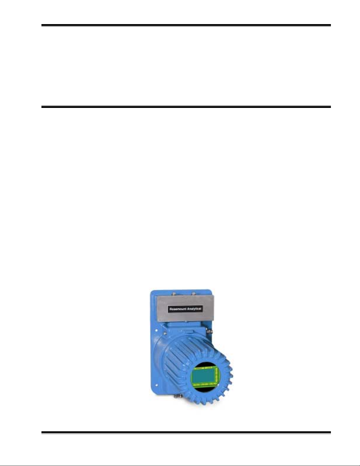
F
IGURE
1-1. CAT 200 C
ONTINUOUS ANALYZER TRANSMITTER
748446-C Rosemount Analytical March 2001
Model CAT 200 Continuous Analyzer Transmitter
1

NTRODUCTION
I
1.2 TYPICAL APPLICATIONS
The CAT 200 Continuous Analyzer Transmitter supports a variety of industry
applications, drawing on more than 40 years of development and process expertise in
sensors, digital signal processing and software technologies. The CAT 200 can satisfy
the most demanding single or multi-component analysis requirements. More than 60
gas components can be measured including:
Carbon Monoxide (CO) Carbon Dioxide (CO2) Methane (CH4)
Hexane (CH equiv.) (C6H14) Water Vapor (H2O) Oxygen (O2)
Hydrogen (H2) Helium (He) Argon (Ar)
Some standard industry applications include:
ETROCHEMICAL REFINERY
P
Light Naphtha Isomerization
H2, CO and CO2 in make-up Hydrogen Gas to Combined Feed
H2 in Scrubber Off Gas to Refinery Fuel Gas Header
Catalytic Reforming
H2 in Recycle Gas from Product Separator
H2 in Net Gas from Net Gas Knockout Drum
H2 in CCR Nitrogen Header
H2 in Surge Hopper Vent
Fluidized Catalytic Cracking
CO and O2 Monitoring of Fluidized Catalytic Cracking Regenerator Gas
Sulfur Recovery Units
Propylene in Feed to Sulfur Recovery Plant
ETROCHEMICAL COMPLEX
P
Ethylene in Primary and Secondary De-Methanizer Overhead
CO2 in Ethane-Ethylene Splitter
Propylene in Splitter Bottoms
MMONIA AND UREA
A
H2, CO and CO2 in Synthesis Gas
TILITIES
U
H2 in Cooling Gas in Turbine Generators
Continuous Emission Monitoring Systems (CEMS)
ET ALS
M
H2 in Endothermic Furnace
LL APPLICATIONS
A
Continuous Emission Monitoring Systems (CEMS)
2
March 2001 Rosemount Analytical 748446-CModel CAT 200 Continuous Analyzer Transmitter

D
ETECTOR METHODOLOGIES
2
The CAT 200 can employ up to two of four diff erent measuring methods depending on
the configuration chosen. The methods are: NDIR, Paramagnetic O2, Electrochemical
O2, and Thermal Conductivity.
2.1 NON-DISPERSIVE INFRARED (NDIR)
The non-dispersive infrared method is based on the principle of absorption of infrared
radiation by the sample gas being measured. The gas-specific wavelengths of the
absorption bands characterize the type of gas while the strength of the absorption
gives a measure of the concentration of the gas component being measured.
An optical bench is employed comprising an infrared light source, two analysis cells
(reference and measurement), a chopper wheel to alternate the radiation intensity
between the reference and measurement side, and a photometer detector. The
detector signal thus alternates between concentration dependent and concentration
independent values. The difference between the two is a reliable measure of the
concentration of the absorbing gas component.
Depending on the gas being measured and its concentration, one of two different
measuring methods may be used as follows:
2.1.1 I
NTERFERENCE FILTER CORRELATION METHOD
With the IFC method the analysis cell is alternately illuminated with filtered infrared
concentrated in one of two spectrally separated wavelength ranges. One of these two
wavelength bands is chosen to coincide with an absorption band of the sample gas
and the other is chosen such that none of the gas constituents expected to be
encountered in practice absorbs anywhere within the band.
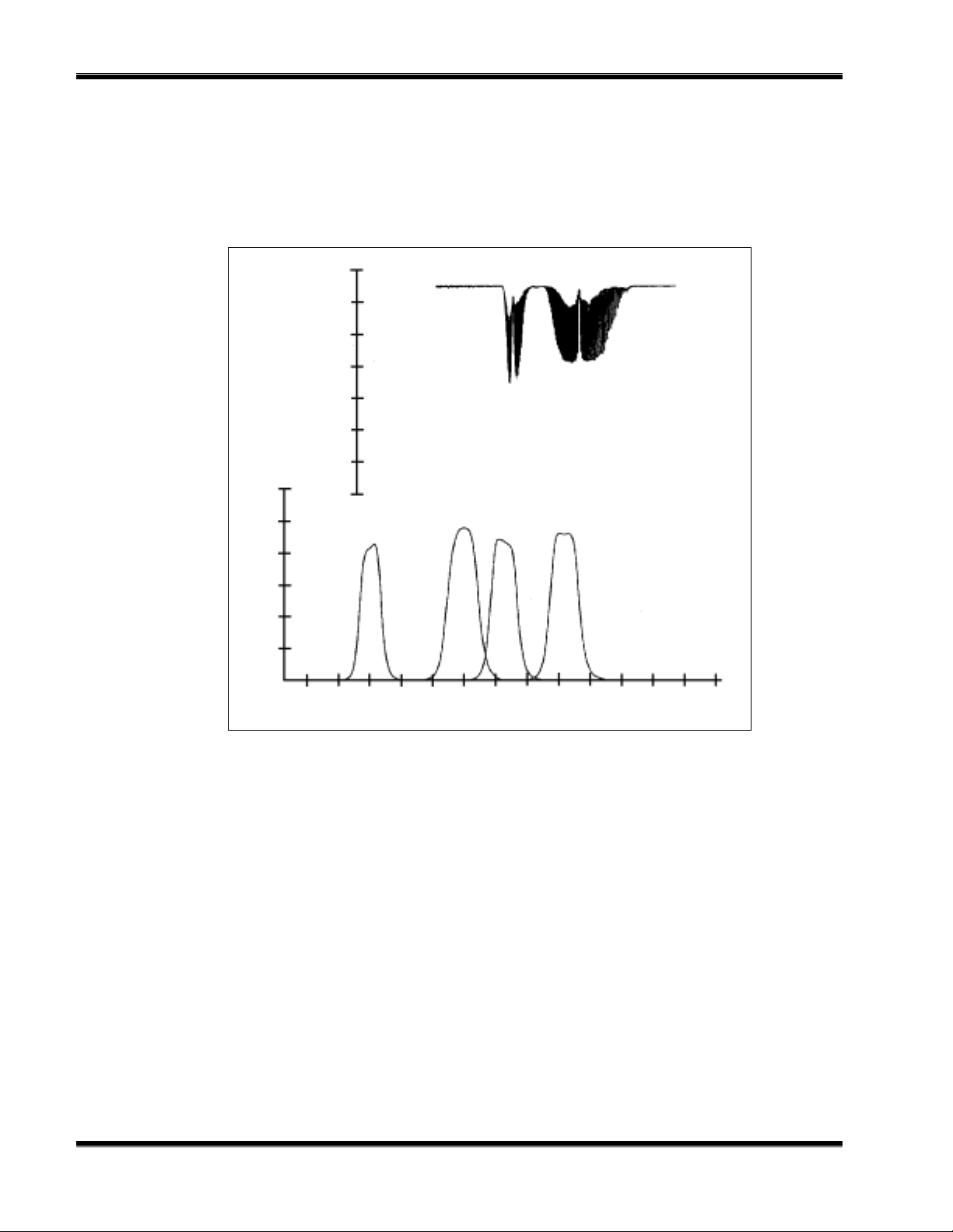
The spectral transmittance curves of the interference filters used in the CAT 200
analyzer and the spectral absorption of the gases CO and CO2 are shown in Figure 2-
1. It can be seen that the absorption bands of these gases each coincide with the
passbands of one of the interference filters. The forth interference filter, used for
generating a reference signal, has its passband in a spectral region where none of
these gases absorb. Most of the other gases of interest also do not absorb within the
passband of this reference filter.
748446-C Rosemount Analytical March 2001
Model CAT 200 Continuous Analyzer Transmitter
3
ETECTOR METHODOLOGIES
D
The signal generation is accomplished with a pyroelectrical (solid-state) detector. The
detector records the incoming infrared radiation. This radiation is reduced by the
absorption of the gas at the corresponding wavelengths. By comparing the
measurement and reference wavelength, an alternating voltage signal is produced.
This signal results from the cooling and heating of the pyroelectric detector material
2
CO
Transmittance (%)
0 15 30 54 60 75 90
CO
Absorption Band
F
IGURE
Transmittance (%)
0 18 36 54 72 90
3000 3200 3400 3600 3800 4000 4200 4400 4600 4800 5000 5200 5400 5600
2-1. A
BSORPTION BANDS OF SAMPLE GAS AND TRANSMITTANCE OF
I
NTERFERENCE FILTERS
HC CO2 CO
Reference
Wave Length (nm)
4
March 2001 Rosemount Analytical 748446-CModel CAT 200 Continuous Analyzer Transmitter

ETECTOR METHODOLOGIES
D
2.1.2 O
PTO-PNEUMATIC METHOD
In the opto-pneumatic method, a thermal radiator generates the infrared radiation
which passes through the chopper wheel. This radiation alternately passes through
the filter cell and reaches the measuring and reference side of the analysis cell with
equal intensity. After passing another filter cell, the radiation reaches the pneumatic
detector.
The pneumatic detector compares and evaluates the radiation from the measuring
and reference sides of the analysis cell and converts them into voltage signals
proportional to their respective intensity.
The pneumatic detector consists of a gas-filled absorption chamber and a
compensation chamber which are connected by a flow channel in which a Microflow
filament sensor is mounted. This is shown in Figure 2-2.
In principle the detector is filled with the infrared active gas to be measured and is only
sensitive to this distinct gas with its characteristic absorption spectrum. The absorption
chamber is sealed with a window which is transparent for infrared radiation. The
window is usually Calcium Fluoride (CaF2).
When the infrared radiation passes through the reference side of the analysis cell into
the detector, no pre-absorption occurs. Thus, the gas inside the absorption chamber is
heated, expands and some of it passes through the flow channel into the
compensation chamber.
F
IGURE
2-2. O
Absorption chamber
Flow channel with
Microflow sensor
PTO-PNEUMATIC GAS DETECTOR
CaF2 Window
Compensation chamber
748446-C Rosemount Analytical March 2001
Model CAT 200 Continuous Analyzer Transmitter
5

ETECTOR METHODOLOGIES
D
When the infrared radiation passes through the open measurement side of the
analysis cell into the detector, a part of it is absorbed depending on the gas
concentration. The gas in the absorption chamber is, therefore, heated less than in the
case of radiation coming from the reference side. Absorption chamber gas becomes
cooler, gas pressure in the absorption chamber is reduced and some gas from the
compensation chamber passes through the flow channel into the absorption chamber.
The flow channel geometry is designed in such a way that it hardly impedes the gas
flow by restriction. Due to the radiation of the chopper wheel, the different radiation
intensities lead to periodically repeated flow pulses within the detector.
The Microflow sensor evaluates these flow pulses and converts them into electrical
pulses which are processed into the corresponding analyzer output.
2.1.3 O
VERALL
NDIR M
ETHOD
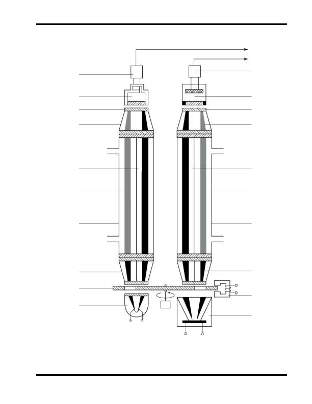
In the case of dual-channel analyzers, the broadband emission from two infrared
sources pass through the chopper wheel. In the case of the Interference Filter
Correlation (IFC) method, the infrared radiation then passes through combinations of
interference filters. In the case of the opto-pneumatic method, the infrared radiation
passes through an optical filter depending on the application and need for reduction of
influences. Then the infrared radiation enters the analysis cells from which it is
focused by filter cells onto the corresponding detector. The preamplifier detector
output signal is then converted into the analytical results expressed directly in the
appropriate physical concentration units such as percent volume, ppm, mg/Nm3, etc.
This is shown in Figure 2-3.
6
March 2001 Rosemount Analytical 748446-CModel CAT 200 Continuous Analyzer Transmitter
ETECTOR METHODOLOGIES
D
To electronics
Preamplifier
Pneumatic or
pyroelectric detector
(solid-state detector)
window
Filter cell without dividing
wall (IFC) with optical
filters
reference side
measuring side
Preamplifier
Duplex filter disc
VIS / UV
semiconductor detector
window
Filter cell without
dividing wall (IFC)
with optical filters
reference side
measuring side
F
IGURE
Analysis cell
Filter cell with
dividing wall (IR)
Chopper blade
IR source with
reflector
2-3. O
VERALL
NDIR M
ETHOD
Motor
Analysis cell
Filter cell with
dividing wall (UV)
Eddy current drive
VIS / UV source
with reflector
748446-C Rosemount Analytical March 2001
Model CAT 200 Continuous Analyzer Transmitter
7

ETECTOR METHODOLOGIES
D
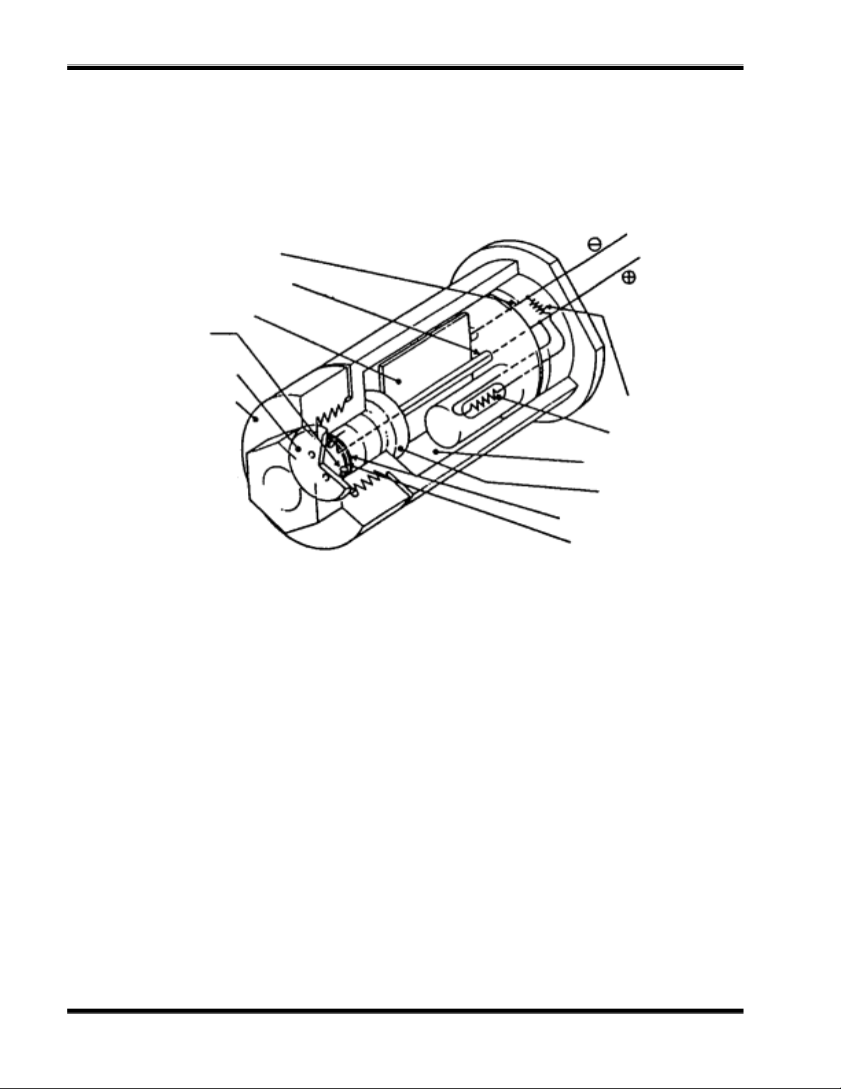
2.2 PARAMAGNETIC OXYGEN METHOD
The paramagnetic principle refers to the induction of a weak magnetic field, parallel
and proportional to the intensity of a stronger magnetizing field.
The paramagnetic method of determination of oxygen concentration utilizes nitrogen
filled quartz spheres arranged at opposite ends of a bar, the center of which is
suspended by and free to rotate on a thin platinum wire ribbon in a cell. Nitrogen (N2)
is used because it is diamagnetic or repelled by a magnet.
A small mirror that reflects a light beam coming from a light source to a photodetector,
is mounted on the platinum ribbon. A strong permanent magnet specifically shaped to
produce a strong, highly inhomogeneous magnetic field inside the analysis cell, is
mounted outside the wall of the cell.
When oxygen molecules enter the cell, their paramagnetism will cause them to be
drawn towards the region of greatest magnetic field strength. The oxygen molecules
thus exert different forces on the two suspended nitrogen filled quartz spheres,
producing a torque which causes the mirror to rotate away from its equilibrium
position.
The rotated mirror deflects the incident light onto the photodetector creating an
electrical signal which is amplified and fed back to a coil attached to the bar holding
the quartz spheres, forcing the suspended spheres back to the equilibrium position.
The current required to generate the restoring torque to return the quartz bar to its
equilibrium position is a direct m easure of the O2 concentration in the sample gas.
The complete paramagnetic analysis cell consists of an analysis chamber, permanent
magnet, processing electronics, and a temperature sensor. The temperature sensor is
used to control a heat exchanger to warm the measuring gas to about 55 °C. Ref er to
Figure 2-4.
8
March 2001 Rosemount Analytical 748446-CModel CAT 200 Continuous Analyzer Transmitter
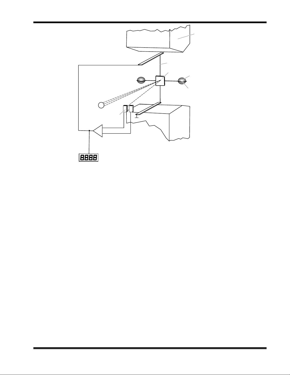
Light
Source
Amplifier
Photodetector
Platinum Wire
Mirror
ETECTOR METHODOLOGIES
D
Permanent Magnet
Quartz Sphere(s)
Wire Loop
F
IGURE
2-4. P
Display
ARAMAGNETIC OXYGEN ANALYSIS
748446-C Rosemount Analytical March 2001
Model CAT 200 Continuous Analyzer Transmitter
9
ETECTOR METHODOLOGIES
D
2.3 ELECTROCHEMICAL OXYGEN METHOD
The electrochemical method of determining oxygen concentration is based on the
galvanic cell principle shown in Figure 2-5.
Black
Lead Wire (Anode)
Lead Wire (Cathode)
Anode (Lead)
O-Ring
Plastic Disc
Plastic Disk
Acid Electrolyt e
Red
Thermistor
Resistor
Sponge Disc
Cathode (Gold Film)
Teflon Membrane
F
IGURE
2-5. E
LECTROCHEMICAL OXYGEN SENSOR
The electrochemical oxygen sensor incorporates a lead and gold galvanic process
with a lead anode and a gold cathode, using an acid electrolyte.
Oxygen molecules diffuse through a non-porous Teflon membrane into the
electrochemical cell and are reduced at the gold cathode. Water is the byproduct of
this reaction.
On the anode, lead oxide is formed which is transferred into the electrolyte. The lead
anode is continuously regenerated and, therefore, the electrode potential remains
unchanged for a long time. The rate of diffusion and corresponding response time (t90)
of the sensor is dependent on the thickness of the Teflon membrane.
The electric current between the electrodes is proportional to the O2 concentration in
the sample gas being measured. The resultant signal is measured as a voltage across
the resistor and thermistor, the latter of which is used for temperature compensation.
A change in the output voltage (mV) represents oxygen concentration.
10
March 2001 Rosemount Analytical 748446-CModel CAT 200 Continuous Analyzer Transmitter
ETECTOR METHODOLOGIES
(
)
(
)
)
)
D
NOTE:
The electrochemical O2 cell requires a minimum internal consumption of
oxygen. Sample gases with an oxygen concentration of less than 2% could
result in a reversible detuning of sensitivity and the output will become
unstable. The recommended practice is to purge the cell with conditioned
ambient air between periods of measurement. If the oxygen concentration is
below 2% for several hours or days, the cell must be regenerated for about one
day with ambient air. Temporary flushing with nitrogen (N2) for less than one
hour (analyzer zeroing) will have no effect on the sensitivity or stability.
Red
Thermistor (5
(-) (+)
Gold Lead
Cathode (2) Anode (1)
O2 + 4 H + 4 e → 2 H2O2 Pb + 2 H
Summary reaction O2 + 2 Pb → 2 PbO
V out
Electrolyte (3)
(ph 6)
Black
Resistor (6
O → 2PbO + 4 H + 4 e
2
F
IGURE
748446-C Rosemount Analytical March 2001
2-6. R
EACTION OF GALVANIC CELL
Model CAT 200 Continuous Analyzer Transmitter
11
ETECTOR METHODOLOGIES
D
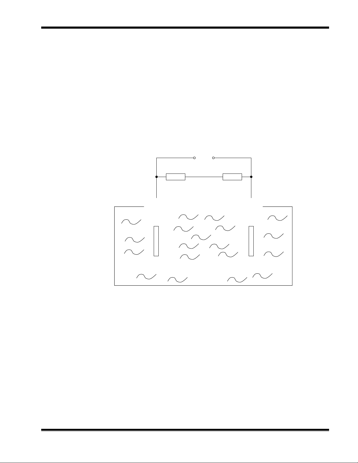
2.4 THERMAL CONDUCTIVITY METHOD
Thermal conductivity is an efficient method to measure two-component gas mixtures
such as H2, HE, CO2 and Ar.
Thermal conductivity measuring cells incorporate electrically heated wires with cooling
rates that are influenced by the sample gas in the cell. The cell combines short
response time with minimum interference, which can be effected by variations in the
sample gas flow rate.
The measuring cells consist of an outer ring enclosing a inner cylindrical chamber.
This chamber contains two lateral passages, each equipped with two thermal sensor
devices. One passage is supplied with sample gas and the other is supplied with an
optional reference gas or a closed loop. A variable bypass arrangement permits
adjustments of response time versus flow rate dependence. The cell can be set
between extremes of fast response with relative high dependence on flow rate, or low
response time with least dependence on sample flow rate by rotating the outer section
with respect to the inner section.
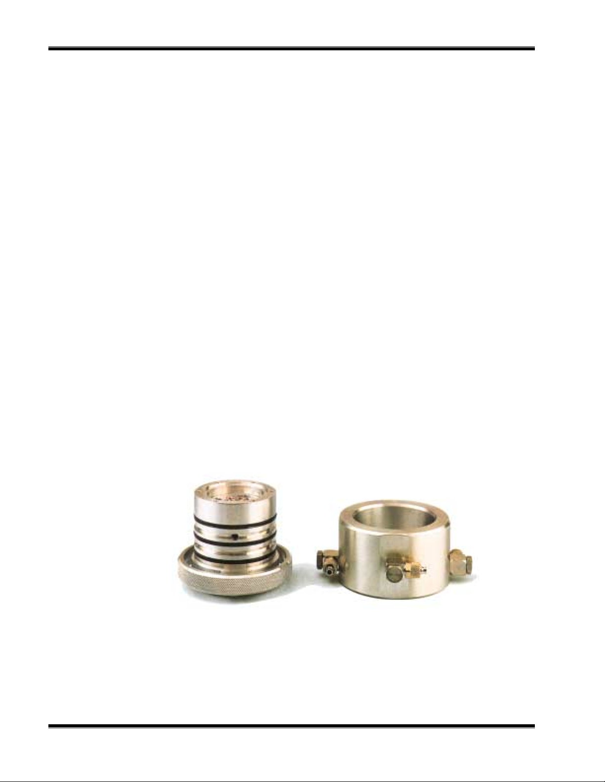
Both the cell volume and the mass of its measurement resistor have been minimized
on order to obtain short response time. A nickel resistor is placed between two
superimposed square ceramic plates which form the walls of the measurement cell.
The cell volume is approximately 1 µl. A total of four such cells are integrated to form
the sensor, two of these function as the measurement cells, and the other two function
as the reference cells. The latter may be either sealed off, or connected to a flow of a
reference gas.
F
IGURE
12
2-7. T
Inner chamber
HERMAL CONDUCTIVITY SENSOR
Outer chamber
March 2001 Rosemount Analytical 748446-CModel CAT 200 Continuous Analyzer Transmitter
 Loading...