

Rosemount Manual: BINOS 100 Series Analyzers including OXYNOS 100, HYDROS 100-1st Ed. | Rosemount Manuals & Guides

Rosemount Analytical
Operation Manual
Series 100
Microprocessor - Controlled Gas Analyzers
BINOS® 100
BINOS® 100 F
BINOS® 100 M
BINOS® 100 2M
OXYNOS® 100
HYDROS® 100
1. Edition 06/2000
ETC00265(1) Series 100 e 23.06.2000
Catalog - No.: ETC00265

Rosemount Analytical
This Maintenance & Operation Manual includes information about the operation of the instrument as well
as additional indications and notes regarding maintenance, troubleshooting and repair.
Troubleshooting, component replacement and internal adjustments must be made by qualified
service personnel only.
Fisher-Rosemount GmbH & Co assumes no liability for any omissions or errors in this manual.
Any liability for direct or consequential damages - which might occur in connection with the delivery or the
use of this manual - is definitely excluded to the extend permitted by applicable law.
This instrument has left the works in good order according to safety regulations.
To maintain this operating condition, the user must strictly follow the instructions and consider the
warnings in this manual or provided on the instrument.
Misprints and alterations reserved
©
2000 by FISHER-ROSEMOUNT GmbH & Co. (PAD/ETC)
1. Edition: 06/2000
Read this operation manual carefully before attempting to operate the analyzer !
For expedient handling of reports of defects, please include the model and serial number which
can be read on the instrument identity plate.
Look for the error check list please too (see chapter 32. of this manual)
Fisher - Rosemount GmbH & Co.
European Technology Center
Industriestrasse 1
D - 63594 Hasselroth • Germany
Phone + 49 (6055) 884-0
Telefax + 49 (6055) 884-209
Internet: http://www.processanalytic.com
ETC00265(1) Series 100 e 23.06.2000

Rosemount Analytical
I. Intended Use Statement S - 1
II. Safety Symbols S - 1
III. General S - 2
IV. Gases and Gas Conditioning (Sample Handling) S - 4
V. Supply Voltage S - 4
VI. Analyzer specific notes for the user S - 6
CONTENTS
Table of Contents
SAFETY SUMMARY S - 1
VII. BINOS® 100 F specific notes for use in hazardous areas S - 7
VII.a Z purge for CSA-C/US Ex Zone 2 Non-Flammable AtmospheresS - 8
VIII. Additional notes for service / maintenance S - 9
VIII.a Electrostatic Discharge S - 10
IX. Operating Conditions according to DMT Approval S - 11
PREFACE P - 1
General Overview P - 1
a) Software Versions P - 1
b) Housing Versions P - 2
Area Classification P - 3
a) General Purpose P - 3
b) Hazardous Areas P - 3
Ex Zone 2 P - 3
Ex Zone 1 P - 3
ETC00265(1) Series 100 e xx.05.2000
I

CONTENTS
DESCRIPTION
1. Technical Description 1 - 1
1.1 Front View 1 - 1
1.2 Rear Panel 1 - 5
1.3 Internal Construction 1 - 11
1.3.1 Internal Gas Paths 1 - 25
a) Gas Path Material 1 - 25
b) Gas Path Layout (internal tubing) 1 - 26
2. Measuring Principle 2 - 1
2.1 IR Measurement 2 - 1
Rosemount Analytical
2.1.1 Interference Filter Correlation (IFC Principle) 2 - 1
2.1.2 Opto-Pneumatic Measuring Principle 2 - 3
2.1.3 Technique 2 - 5
2.2 Oxygen Measurement 2 - 6
2.2.1 Paramagnetic Measurement 2 - 6
2.2.2 Elektrochemical Measurement 2 - 8
2.3 Thermal Conductivity Measurement 2 - 10
2.3.1 Sensor Design 2 - 10
2.3.2 Analysis Cell 2 - 10
2.3.3 Measurement Method 2 - 11
3. Photometer Assembly 3 - 1
3.1 Photometer with Pyroelectrical Detector (Solid-state detector) 3 - 1
3.2 Photometer with Gas Detector 3 - 4
4. (vacant)
II
ETC00265(1) Series 100 e xx.05.2000

Rosemount Analytical
5. Preparation of Start-up 5 - 1
5.1 Installation Site 5 - 2
5.2 Gas Conditioning (Sample Handling) 5 - 3
5.2.1 Fine Dust Filter (Option BINOS® 100 2M/F) 5 - 4
5.2.2 Gas Sampling Pump (Option BINOS® 100 2M/F) 5 - 4
5.2.3 Pressure Sensor (Option) 5 - 4
5.2.4 Gas Flow 5 - 4
5.3 Gas Connections 5 - 5
5.3.1 Standard 5 - 5
5.3.2 Internal Solenoid Valves (Option BINOS® 100 2M/F) 5 - 8
CONTENTS
OPERATION
5.3.3 Purge gas connection of BINOS® 100 F for Ex zones 5 - 10
a) Continuous Purge (for CENELEC Ex Zone 1 Applications) 5 - 10
b) Z purge for US Ex Zone 2 Non-Flammable Atmospheres 5 - 11
5.4 Additional Hints to BINOS® 100 F (Field Housing) 5 - 12
5.4.1 Wall Mounting 5 - 13
5.4.2 Electrical Connections 5 - 14
6. Switching On 6 - 1
6.1 General 6 - 1
6.2 24 V DC Supply 6 - 2
6.3 230/120 V AC Supply 6 - 4
6.3.1 BINOS® 100 2M 6 - 4
6.3.2 BINOS® 100 F 6 - 5
7. Key Functions 7 - 1
7.1 FUNCTION 7 - 2
7.2 ENTER 7 - 3
7.3 INPUT - CONTROL 7 - 5
7.4 PUMP (BINOS® 100 2M/F only) 7 - 6
ETC00265(1) Series 100 e xx.05.2000
III

CONTENTS
Rosemount Analytical
8. Entry of System Parameters 8 - 1
8.1 Pressure Correction 8 - 2
8.2 Cross Compensation (internal) 8 - 2
8.3 Cross Compensation Calibration (internal) 8 - 3
8.4 Hold 8 - 4
8.5 Automatic Calibration 8 - 4
8.6 Tolerance Check 8 - 5
8.7 Display Off 8 - 6
8.8 Analog Signal Outputs 8 - 7
8.9 Flushing Period 8 - 8
8.10 User Code 8 - 8
8.11 Response Time (t90)8 - 9
8.12 Offset (Begin of range) 8 - 10
8.13 End of Range Value 8 - 11
8.14 Reset 8 - 12
8.15 Program Version 8 - 13
8.16 Serial - No. 8 - 13
8.17 Pump 8 - 14
8.18 Pump Control 8 - 14
9. Calibration 9 - 1
9.1 Manual Calibration 9 - 2
9.1.1 Zeroing 9 - 2
9.1.2 Spanning 9 - 4
9.2 Time-Controlled Calibration Mode (Option) 9 - 7
9.2.1 Zeroing 9 - 7
9.2.2 Combined Zeroing and Spanning 9 - 9
9.3 Remote-Controlled Calibration Mode (Option) 9 - 10
10. Measurement / Switching Off 10 - 1
10.1 Measurement 10 - 1
10.2 Switching Off 10 - 2
11. Digital Outputs 11 - 1
11.1 Concentration Limits 11 - 2
11.2 Valve Control 11 - 4
11.3 Status Signals (Option non-voltage-carrying relay contacts) 11 - 4
IV
ETC00265(1) Series 100 e xx.05.2000

Rosemount Analytical
12. Serial Interface (Option) 12 - 1
12.1 Retrofitting of Serial Interface / Status Signals 12 - 1
12.2 General 12 - 2
12.3 Start Up 12 - 4
12.3.1 RS 232 C 12 - 4
12.3.2 RS 485 12 - 5
12.3.3 Switching ON/OFF Interface Operation 12 - 6
12.3.4 Setting Interface Parameters 12 - 6
12.4 Telegram Syntax 12 - 8
12.4.1 Start Character ( “$” = Hex 24) 12 - 8
CONTENTS
OPTIONS
12.4.2 Terminate Character ( “CR” = Hex OD) 12 - 8
12.4.3 Instruction Code 12 - 8
12.4.4 Hyphen Character ( “;” = Hex 3B) 12 - 8
12.4.5 Status Telegram 12 - 9
12.4.6 Numerical Representations 12 - 10
12.4.7 Block Parity Check 12 - 10
12.5 Instruction Syntax 12 - 11
12.5.1 Instruction Listing 12 - 12
12.5.2 Response Telegrams 12 - 13
13. Digital Inputs/FOUNDATION™ Fieldbus (BINOS
®
100 2M/F only) 13 - 1
13.1 Digital Inputs 13 - 1
13.1.1 General 13 - 1
13.1.2 Start of Calibration 13 - 1
13.1.3 Valve Control 13 - 2
13.1.4 Pump Control 13 - 2
13.2 FOUNDATION™ Fieldbus 13 - 2
14. Cross Compensation/Setting of Respsonse time (TC only) 14 - 1
14.1 Cross Compensation 14 - 1
14.1.1 Previous Adjustment 14 - 2
14.1.2 Adjustment Procedure 14 - 3
15. (vacant)
ETC00265(1) Series 100 e xx.05.2000
V

CONTENTS
TROUBLESHOOTING
16. Error List 16 - 1
17. Measuring Points of BKS and OXS 17 - 1
17.1 Measuring points of BKS 17 - 1
17.1.1 Supply Voltage + 6 V 17 - 1
17.1.2 Reference Voltage positive 17 - 1
17.1.3 Reference Voltage negative 17 - 2
17.1.4 Motor Drive (for IR channel only) 17 - 2
17.1.5 Temperature Sensor 17 - 3
17.1.6 Light Barrier Signal 17 - 4
Rosemount Analytical
17.1.7 Analog Preamplifiering 17 - 5
17.2 Measuring points of OXS (EO2 measurement) 17 - 6
17.2.1 Sensor Signal 17 - 6
18. Plug Pin Allocation of Printed Circuit Boards 18 - 1
18.1 Plug Pin Allocation of BKS 18 - 1
18.1.1 IR measurement without oxygen channel 18 - 2
18.1.2 Oxygen Measurement without IR channel 18 - 2
18.1.3 IR / Oxygen Measurement combined 18 - 3
18.1.4 TC Measurement without IR channel 18 - 3
18.1.5 IR / TC Measurement combined 18 - 4
18.1.6 Oxygen / TC Measurement combined 18 - 4
18.2 Plug Pin Allocation OXS (EO2 measurement only) 18 - 5
18.3 Plug Pin Allocation WAP 100 (TC measurement only) 18 - 6
19. Jumper Allocation of BKS 19 - 1
20. (vacant)
VI
ETC00265(1) Series 100 e xx.05.2000

Rosemount Analytical
21. Fine Dust View Filter (Option) 21 - 1
22. Leak Testing 22 - 1
23. Housing 23 - 1
23.1 Cleaning of Housing Outside 23 - 1
23.2 Opening the Housing 23 - 2
23.2.1 1/4 19" Housing 23 - 2
23.2.2 BINOS® 100 2M 23 - 3
CONTENTS
MAINTENANCE
a) Housing Cover 23 - 3
b) Front Panel 23 - 4
23.2.3 BINOS® 100 F (Field Housing) 23 - 5
24. Replacement and Cleaning of Photometric Components 24 - 1
24.1 Removal of the Photometer Assembly 24 - 1
24.2 Light Source Replacement 24 - 2
24.3 Cleaning of Analysis Cells and Windows 24 - 3
24.3.1 Removal of Analysis Cells 24 - 3
24.3.2 Cleaning 24 - 4
24.3.3 Reinstalling of Analysis Cells 24 - 5
24.4 Chopper Replacement 24 - 6
24.5 Reinstalling of the Photometer Assembly 24 - 6
24.6 Physical Zeroing 24 - 7
24.6.1 Standard Photometer (not sealed version) 24 - 7
24.6.2 Sealed Photometer (Option) 24 - 8
ETC00265(1) Series 100 e xx.05.2000
VII

CONTENTS
25. Check / Replacement of electrochemical Oxygen Sensor 25 - 1
25.1 Check of the Sensor 25 - 2
25.2 Replacement of the Sensor 25 - 3
25.2.1 Removal of the Sensor 25 - 3
a) Oxygen Measurement without IR channel 25 - 3
b) IR / Oxygen Measurement combined 25 - 5
25.2.2 Exchange of the Sensor 25 - 6
25.2.3 Reinstalling of the Sensor 25 - 6
a) Oxygen Measurement without IR channel 25 - 6
b) IR / Oxygen Measurement combined 25 - 6
25.2.4 Basic conditions for the Oxygen Sensor 25 - 7
Rosemount Analytical
26. (vacant)
27. TECHNICAL DATA 27 - 1
27.1 Options 27 - 1
27.2 Housing 27 - 2
27.3 Signal Inputs / Outputs, Interfaces 27 - 3
27.4 General Specifications 27 - 7
27.5 Voltage Supply 27 - 9
27.5.1 Electrical Safety 27 - 9
27.5.2 Power Supplys [UPS 01 T (Universal Power Supply) / SL10 / SL5] 27 - 10
VIII
ETC00265(1) Series 100 e xx.05.2000

Rosemount Analytical
28. Replacing the EPROM 28 - 1
29. Pin Assignments 29 - 1
29.1 24 V DC Input 29 - 1
29.2 24 V DC Output 29 - 1
29.3 230/120 V AC Input 29 - 2
29.4 Analog Signal Outputs 29 - 2
29.5 Digital Signal Outputs 29 - 3
29.5.1 Standard Signal Outputs 29 - 3
29.5.2 Status Signals (Relay Outputs, Option) 29 - 3
CONTENTS
SUPPLEMENT
29.6 Serial Interface (Option) 29 - 4
29.7 Analog Signal Inputs (TC Option Cross Compensation) 29 - 4
29.8 Digital Signal Inputs (Option) 29 - 5
29.9 FOUNDATION™ Fieldbus (Option) 29 - 5
29.10 Wiring of Digital Inputs and Outputs
to ensure electromagnetic immunity 29 - 6
29.10.1 Electrical connections (general) 29 - 6
29.10.2 Special Tips 29 - 8
30. Connection Cables 30 - 1
30.1 24 V DC 30 - 1
30.2 230/120 V AC Input (BINOS® 100 2M) 30 - 1
30.3 Sub D Sockets, 9 pin 30 - 2
30.4 Sub D Plugs, 9 pin 30 - 2
31. (vacant)
32. Failure Check List 32 - 1
INDEX I - 1
List of figures and tables I - 11
ETC00265(1) Series 100 e xx.05.2000
IX

CONTENTS
Rosemount Analytical
X
ETC00265(1) Series 100 e xx.05.2000
Rosemount Analytical
SAFETY SUMMARY
Safety Summary
I. Intended Use Statement
The series 100 instruments are intended for use an industrial measurement device only. It is not
intended for use in medical, diagnostic, or life support applications, and no independent agency
certifications or approvals are to be implied as covering such applications.
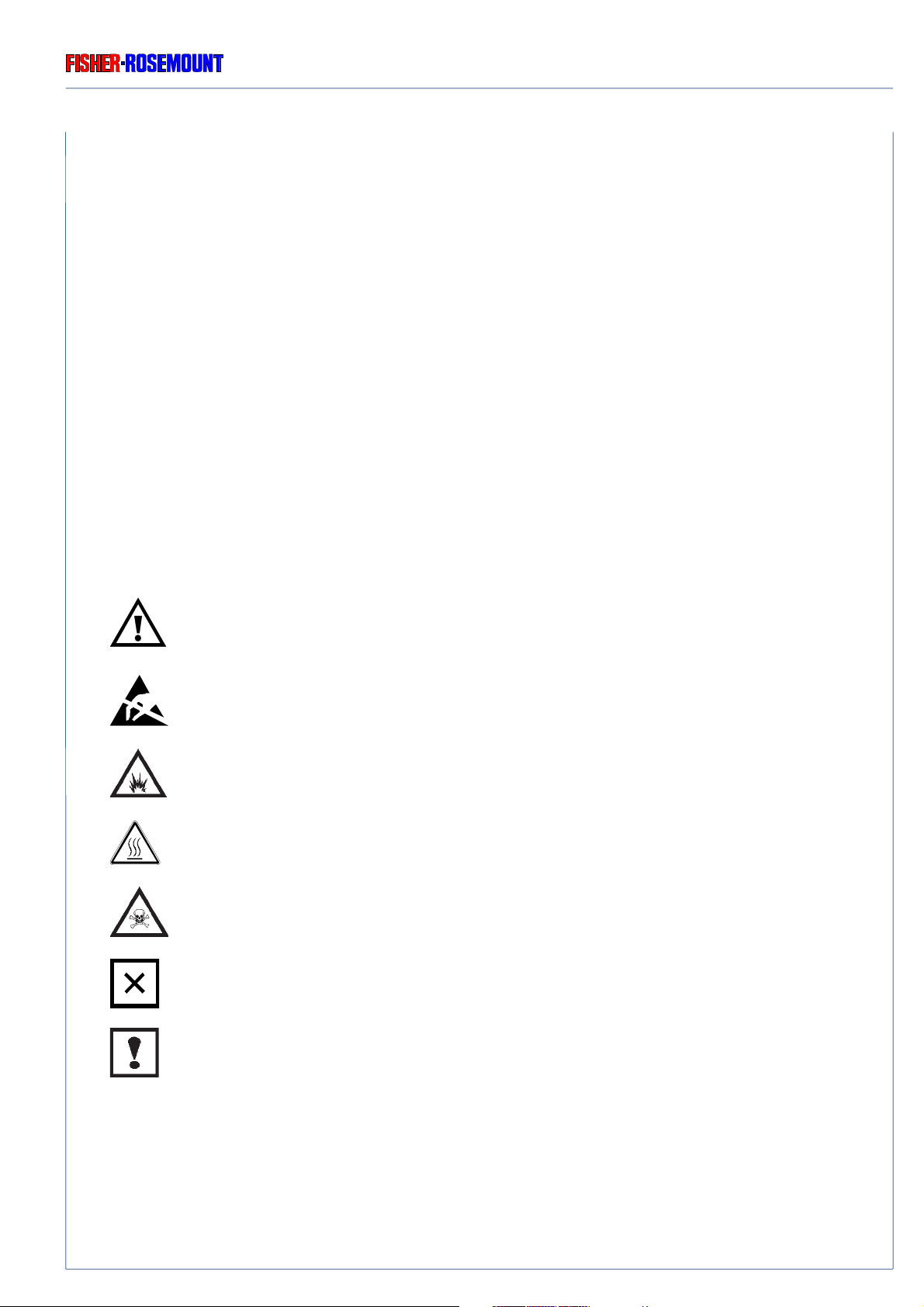
II. Safety Symbols
GENERAL
Outside and/or inside the 100 series instruments or at operation manual resp. different symbols
give you a hint to special sources of danger.
Source of danger !
See Operation Manual!
Electrostatic Discharge (ESD) !
Explosives !
Hot components !
Toxic !
Risk to health !
Analyzer specific notes for the user !
For additional information to these safety symbols see operation manual.
Strictly follow these instructions !
ETC00265(1) Series 100 e 23.06.2000
S - 1

SAFETY SUMMARY
GENERAL
Rosemount Analytical
III. General
◆ To avoid explosion, loss of life, personal injury and damages to this equipment and other
property, all personnel authorized to install, operate and service this equipment should be
thoroughly familiar with and strictly follow the instructions in this manual !
Save these instructions !
◆ If this equipment is used in a manner not specified in these instructions, protective features
may be impaired !
◆ Correct and safe operation of analyzers calls for appropriate transportation and storage,
expert installation and commissioning as well as correct operation and meticulous
maintenance !
◆ Fisher-Rosemount GmbH & Co. does not take responsibility (liability) for the customer´s
failure to comply with these requirements !
◆ Do not attempt internal service or adjustment unless other person, capable of rendering first
aid and resuscitation, is present !
◆ Because of the danger of introducing additional hazards, do not perform any unauthorized
modification to the instrument !
Return the instrument to a Fisher-Rosemount Sales and Service office for service or repair
to ensure that safety features are maintained !
◆ Instruments which appear damaged or defective should be made inoperative and secured
against unintended operation until they can be repaired by qualified service personnel.
S - 2
ETC00265(1) Series 100 e 23.06.2000

Rosemount Analytical
SAFETY SUMMARY
GENERAL / GASES AND GAS CONDITIONING (SAMPLE HANDLING)
Do not open instrument when energized !
Component replacement and internal adjustments requires servicing by
qualified personnel only !
Read this operation manual before attempting to operate with the instrument !
Be sure to observe the additional notes, safety precautions and warnings given
in the operation manual !
Operate analyzer as table-top version or as rack-mountable version (built-in) only
(except of BINOS® 100 F: designed for wall mounting only) !
Do not operate the instrument in the presence of flammable gases or explosive
atmosphere without supplementary protective measures !
Hot components may exist at the photometer or in heated versions !
Lift or carry housing with at least 2 persons because of the high weight of field
housing BINOS® 100 F (approx. 30 - 35 kg).
For easy transport use a suitable cart.
Verify to BINOS® 100 F, that the PG fittings together with pass through cables are
hermetic to be in agreement with protection class IP 65 (according to DIN standard 40050). The permissible outside diameters of the cables are 7 to 12 mm !
ETC00265(1) Series 100 e 23.06.2000
S - 3

SAFETY SUMMARY
GASES AND GAS CONDITIONING (SAMPLE HANDLING) / SUPPLY VOLTAGE
IV. Gases and Gas Conditioning (Sample Handling)
Be sure to observe the safety regulations for the respective gases
(sample gas and test gases / span gases) and the gas bottles !
Inflammable or explosive gas mixtures must not be purged into the instrument
without supplementary protective measures !
To avoid a danger to the operators by explosive, toxic or unhealthy gas
components, first purge the gas lines with ambient air or nitrogen (N2) before
cleaning or exchange parts of the gas paths.
Rosemount Analytical
V. Supply Voltage
The socket outlet shall be installed near the equipment and shall be easily
accessible to disconnect the device from the socket outlet.
Verify whether the line voltage stated on the instrument ore power supply is in
accordance with that of your mains line!
Be sure to observe the safety precautions and warnings given by
manufacturer of power supply !
◆ BINOS® 100(M), BINOS® 100 2M (external PS), HYDROS® 100 and OXYNOS® 100 are
Safety Class III instruments.
Verify correct polarity for 24 V DC operation !
S - 4
Use only power supply VSE 2000, UPS 01 T, DP 157, SL5, SL10 (DP 157 and
SL for rack mounting only) or equivalent power supplys to be in agreement with
the CE conformity.
If using equivalent power supplys, they must have SELV output voltage !
For supply of more than one analyzer with one power supply, a fuse (T3.15A) is
to be connect in series for each analyzer !
ETC00265(1) Series 100 e 23.06.2000

Rosemount Analytical
◆ BINOS® 100 2M (internal PS) and BINOS® 100 F are Safety Class 1 instruments
The analyzer is provided with a protective earth terminal.
To prevent shock hazard, the instrument chassis and cabinet must be connected
to an electrical ground. The instrument must be connected to the AC power
supply mains through a three-conductor power cable, with the third wire firmly
connected to an electrical ground (safety ground) at the power outlet.
If the instrument is to be energized via an external power supply, that goes for the
power supply too.
Any interruption of the protective (grounding) conductor or disconnection of the
protective earth terminal will cause a potential shock hazard that could result in
personal injury. Deliberate disconnection is inadmissible / prohibited !
SAFETY SUMMARY
SUPPLY VOLTAGE
The analyzer BINOS® 100 F (field housing) has no switch with disconnect
function. The customer has to provide a switch or circuit breaker into his
installation. This switch has to be installed near by analyzer, must be easily
attainable for operator and has to be characterized as disconnector for analyzer.
Cables to external data processing have to be double-insulated against mains
voltage for analyzer BINOS® 100 F !
Use cables suitable for intrinsic safe applications only ! Install internal data lines
that they have a distance to mains voltage lines of at least 5 mm.
This distance has to be valid permanently (e.g. via cable holder) !
24 VDC supply to external components/analyzers with the internal power
supply of BINOS® 100 2M requires a fuse to be connected in series to the
consumer which limits the current consumption to max. 2 A !
Verify correct polarity for 24 V DC supply of external components !
ETC00265(1) Series 100 e 23.06.2000
S - 5

SAFETY SUMMARY
ANALYZER SPECIFIC NOTES FOR USER
VI. Analyzer specific notes for the user
The installation site for the instrument has to be dry and remain above freezing
point at all times.
The instrument must be exposed neither to direct sunlight nor to strong sources
of heat. Be sure to observe the permissible ambient temperature !
For outdoor sites, we recommend to install the instrument in a protective cabinet.
At least, the instrument has to be protected against rain (e.g., shelter).
Do not interchange gas inlets and gas outlets !
All gases have to be supplied to the analyzer as conditionned gases !
If corrosive gases are inserted into the instrument, it has is to be verified that there
Rosemount Analytical
are no gas components which may damage the gas path components.
Ensure that all gas connections are made as labeled and are leak free !
Improper gas connections could result in explosion and death !
The unit´s exhaust may contain hydrocarbons and other toxic gases such as
carbon monoxide ! Carbon monoxide is highly toxic !
Permissible gas pressure max. 1,500 hPa !
The exhaust gas lines have to be mounted in a declining, descending,
pressureless and frost-free and according to the valid emission legislation !
In case it is necessary to open the gas paths, close the analyzers
gas connections with PVC caps immediatly !
Pressure of sample gas / test gases max. 1,500 hPa !
BINOS® 100 F lift points are labeled ! Labels showing down side for transport !
Do not use electronics of optional “purge system” as handle !
S - 6
Use only optional delivered cables from our factory or equivalent shielded cables
to be in agreement with the CE conformity.
The customer has to prove that the shield is connected correctly (chapter 29.10).
Shield and connectors housing have to be connected conductive.
Sub. min. D plugs/sockets have to be screwed to the analyzer.
The analyzer (excepting BINOS® 100 F) is not in agreement with the CE
conformity if optional terminal strip adapters are used In this case CE
conformity must be declared by customer as “manufacturer of system”.
ETC00265(1) Series 100 e 23.06.2000

Rosemount Analytical
BINOS® 100 F SPECIFIC NOTES FOR USE IN HAZARDOUS AREAS (EX ZONES)
VII. BINOS® 100 F specific notes for use in hazardous areas (Ex zones)
Be sure to observe the additional notes, safety precautions and warnings given
in the individual manuals (simplified pressurization for CENELEC ex zone 2 /
EExp approved “purge system” for CENELEC ex zone 1) !
Wall mounting:
Ex zone 1 and Ex zone 2 applications require additional space for safety related
components (see Fig. 27-6, 27-7 and 27-8).
Pressure inside the housing must not exceed 5 hPa at normal operation or
10 hPa for a short time of less than 1/2 hour resp. !
SAFETY SUMMARY
Activation of pressurization bypass switch must be performed by a authorized
person (for hazardous areas) only.
This has to be in accordance with respective legislation only !
Be sure that there is no presence of flammable gases or explosive
atmosphere before opening the housing !
Do not operate with doors open.
Always disconnect power, discharge circuits and remove external voltage
sources before troubleshooting, repair or replacement of any component !
After disconnecting power and and removal of external voltage wait at least
5 minutes before opening the housing !
Cleaning of BINOS® 100 F front panel for Ex Zones:
Danger of electrostatic discharge !
Use damp cloth only for cleaning front panel !
ETC00265(1) Series 100 e 23.06.2000
S - 7

SAFETY SUMMARY
Z PURGE FOR CSA-C/US EX ZONE 2 NON-FLAMMABLE ATMOSPHERES
VII.a Z purge for CSA-C/US Ex Zone 2 Non-Flammable Atmospheres
This enclosure shall not be opened unless the area is known to be free of
flammable materials or unless all devices within have been de-energized !
Upon start-up or after loss of continuous dilution requiring switching off the
electrical supply, purge for 22 minutes with flow rate approx. 23,5 scfh (13 l/min.,
see chapter 5.3.3) unless the internal atmosphere is known to be well below
the lower explosive limit (LEL) !
This analyzer is not designed for analysis of flammable sample !
Introduction of flammable samples into this equipment could result in explosion,
Rosemount Analytical
causing severe personal injury, death or property damage !
Consult factory if flammable samples are to be measured !
Do not open while energized unless it is known that no explosive atmosphere is
present !
S - 8
ETC00265(1) Series 100 e 23.06.2000

Rosemount Analytical
VIII. Additional notes for service / maintenance
Do not open instrument when energized !
Component replacement and internal adjustments requires servicing by
qualified personnel only !
Always disconnect power, discharge circuits and remove external voltage
sources before troubleshooting, repair or replacement of any component !
Any work inside the instrument without switching off the power must be
performed by a specialist who is familiar with the related danger, only !
SAFETY SUMMARY
ADDITIONAL NOTES FOR SERVICE / MAINTENANCE
To avoid a danger to the operators by explosive, toxic or unhealthy gas
components, first purge the gas lines with ambient air or nitrogen (N2) before
the gas paths are cleaned or parts are exchanged.
Do not open BINOS® 100 F for use in hazardous areas (Ex zones) while
energized unless it is known that no explosive atmosphere is present !
Hot components may exist at the photometer or in heated versions !
In case of replacing fuses the customer has to be certain that fuses of specified
type and rated current are used. It is prohibited to use repaired fuses or defective
fuse holders or to short-circuit fuse carriers (fire hazard).
Cleaning of BINOS® 100 F front panel for Ex Zone 1:
Danger of electrostatic discharge !
Use damp cloth only for cleaning front panel !
ETC00265(1) Series 100 e 23.06.2000
S - 9

SAFETY SUMMARY
ELECTROSTATIC DISCHARGE
Rosemount Analytical
VIII.a Electrostatic Discharge
The electronic parts of the analyzer can be irreparably damaged if exposed to electrostatic
discharge (ESD).
The instrument is ESD protected when the covers have been secured and safety precautions
observed. When the housing is open, the internal components are not ESD protected anymore.
Although the electronic parts are reasonable safe to handle, you should be aware of the following
considerations:
Best ESD example is when you walked across a carpet and then touched an electrical grounded
metal doorknob. The tiny spark which has jumped is the result of electrostatic discharge (ESD).
You prevent ESD by doing the following:
Remove the charge from your body before opening the housing and maintain during work with
opened housing, that no electrostatic charge can be built up.
Ideally you are opening the housing and working at an ESD protecting workstation.
Here you can wear a wrist trap.
However, if you do not have such a workstation, be sure to do the following procedure exactly:
Discharge the electric charge from your body. Do this by touching a device that is grounded
electrically (any device that has a three - prong plug is grounded electrically when it is plugged into
a power receptacle).
This should be done several times during the operation with opened housing (especially after
leaving the service site because the movement on a low conducting floors or in the air might cause
additional ESDs).
S - 10
ETC00265(1) Series 100 e 23.06.2000

Rosemount Analytical
OPERATING CONDITIONS ACCORDING TO DMT APPROVAL
SAFETY SUMMARY
IX. Operating Conditions according to DMT Approval
(Chapter 6 of the supplement I to the DMT reports “IBS/PFG-No. 41300392 NIII” and
“IBS/PFG-No. 41300292 NIII” about the performance test of the stationary gas analyzers
BINOS® 100 (M/2M) and OXYNOS® 100.
According to the system version and measuring results included in this report, the stationary gas
analyzer BINOS® 100 2M from Fisher-Rosemount GmbH & Co. is suitable for measuring the
concentrations of methane between 0 and 80 % CH4, of carbon dioxide between 0 and 80 % CO2,
of carbon monoxid between 0 - 200 ppm CO and 0 - 10 Vol.% CO and of oxygen between 0 - 10
Vol.-%, if the features and system version go conform with the details contained in the enclosed
documents as stated in this report, if the analysis system is operated accordingly and if the
following requirements are met:
◆ When using the gas warning system, it must be ensured that the permissible variations will
not be exceeded, taking into account the systematic failures of the measuring signals (as
indicated in this report) and the local operating conditions. Consider the Code of Pratice No.
T032 of the Labor Association of the Chemical Industry "Usage of stationary gas warning
systems for explosion protection".
◆ Verify that the explosion protection requirements are met when using the gas warning
system.
◆ Depending on the situation, it must be verified that the preset values are low enough to allow
the system to activate the necessary protection and emergency measures and, thus, to
prevent any critical situations in a minimum period of time.
◆ When at system installation, a release of one or both measuring components in the ambient
air might occur, its influence on the measuring result should be proved. A sealed cell or an
external housing purging with sample-free air of measuring gases can be used, if required.
◆ The operatability of the alarms and the displays of each system should be tested with clean
air and test gas after the initial operation, after each long-time interruption, and periodically.
The tightness of gas pathes should also be tested. The tests must be documented by
keeping accounts.
ETC00265(1) Series 100 e 23.06.2000
S - 11

SAFETY SUMMARY
OPERATING CONDITIONS ACCORDING TO DMT APPROVAL
Rosemount Analytical
◆ The intervals for the periodical tests must be settled by the person being responsible for the
system´s security and in accordance with the Code of Pratice No. T023 of the Labor
Association of the Chemical Industry "Maintenance of stationary gas warning systems for
explosion protection".
◆ Consider the superproportional dependency of the barometric pressure on the measured
value for CO2.
◆ The system control with serial interfaces described in this operation manual have not been
subject to this investigation.
◆ Sample gas condensation in analyzer (components) must be prevented by taking the
necessary steps.
◆ When the system is used with aggressive gases, it is to be verified that there are no gas
components which might damage the gas path components.
◆ Appropriate dust filters must precede the used systems.
◆ The pressure and flow values recommended by the manufacturer should be observed. An
external monitoring of the sample gas flow through the analyzer should be provided.
◆ The results of this investigation are based on the systems using software versions “3.03”,
“4.00”, “4.01” and “4.11”. A change of the software version used must be certified by the
Testing Association.
◆ It should be ensured that the system parameters for the analog output have been correctly
adjusted. End of range of low concentration should not be identical or lower than the begin
of range. Disregarding these versions, the measurement range should be adjusted between
0 to 80 % CH4, 0 to 80 % CO2, 0 to 10 % CO or 0 to 10 % O2 resp. when the systems are
used for explosion protection.
◆ Read and follow the operation and maintenance manual supplied to and certified by PFG.
It is important that the temperature is kept between 5 and 45 °C.
S - 12
ETC00265(1) Series 100 e 23.06.2000

Rosemount Analytical
OPERATING CONDITIONS ACCORDING TO DMT APPROVAL
SAFETY SUMMARY
◆ The analyzer housings must be provided with a permanent type plate indicating the name
of the manufacturer, model number, serial number, and the following reference and date of
testing:
"IBS/PFG-Nr. 41300392" (for CH4, CO2 or CO)
"IBS/PFG-Nr. 41300292" (for O2)
Other designation requirements, such as these according to ElexV, are still valid. With this
type plate, the manufacturer conformes that the features and technical data of the delivered
system are identical with those described in this report. Any system which is not provided
with such a type plate does not go conform with this report.
◆ The chapter 6 of this report must be included in the operation and maintenance manual.
◆ The manufacturer has to supply the customer with a copy of this report, if required.
◆ A print of the report in an abridged version requires the agreement of PFG.
◆ The results included in this report may not be altered in publications produced by the
manufacturer.
ETC00265(1) Series 100 e 23.06.2000
S - 13

SAFETY SUMMARY
Rosemount Analytical
S - 14
ETC00265(1) Series 100 e 23.06.2000

Rosemount Analytical
PREFACE
General Overview
The series 100 of analyzers offers multi-component, multi-method analysis. Different measurement methods can be combined in one analyzer. The following measuring methods of the
individual measuring channels are possible:
IR = non-dispersive infrared measurement
PO2= paramagnetic oxygen measurement
EO2= electrochemical oxygen measurement
TC = thermal conductivity measurement
PREFACE
All analyzers are designed to measure 1 or 2 gas components except of HYDROS® 100 and
OXYNOS® 100 in case of PO2 measurement (both 1 channel only).
a) Software Versions
Different software versions and analyzer options are delivered:
BINOS® 100 (M), OXYNOS® 100, HYDROS® 100 (1/4 19" housing, external power supply):
Version 4.11 with optional RS 232/485 Interface (according to DMT Approval)
Version 5.0 with optional RS 232/485 Interface
BINOS® 100 2M (1/2 19" housing, internal power supply):
Version 4.11 with optional RS 232/485 Interface (according to DMT Approval)
Version 5.0 with optional RS 232/485 Interface
*)
BINOS® 100 2M (1/2 19" housing, external power supply):
Version 4.11 with optional RS 232/485 Interface (according to DMT Approval)
Version 5.0 with optional RS 232/485 Interface*) and/or with optional 7 digital inputs
Version 5.01 with optional 7 digital inputs and FOUNDATION™ Fieldbus
**)
BINOS® 100 F (field housing, internal power supply):
Version 4.11 with optional RS 232/485 Interface (according to DMT Approval)
Version 5.0 with optional RS 232/485 Interface*) and/or with optional 7 digital inputs
Version 5.01 with optional 7 digital inputs and optional FOUNDATION™ Fieldbus
*)
not in combination with FOUNDATION™ fieldbus
***)
not in combination with RS 232/485 interface
ETC00265(1) Series 100 e 23.06.2000
**)
P - 1

PREFACE
Rosemount Analytical
b) Housing Versions
Different housing versions are delivered (for detailed informations see price list):
BINOS® 100 = 1/4 19" housing, ext. PS one or two IR channel
BINOS® 100 M = 1/4 19" housing, ext. PS, one IR channel and one EO2 channel
BINOS® 100 2M = 1/2 19" housing, one or two IR channel(s) or
internal or external PS, one IR channel and one EO2 channel or
one IR channel and one PO2 channel or
one IR channel and one TC channel or
one PO2 channel and one TC channel or
one EO2 channel and one TC channel or
one ot two PO2 channels
one ot two EO2 channels
one or two TC channels
with standard options: one internal sample gas pump
one internal solenoid valve block
one integrated fine dust filter
one integrated flow indicator
BINOS® 100 F = field housing, int. PS, measuring channels see BINOS® 100 2M
with standard options: see BINOS® 100 2M (dust filter for GP only)
HYDROS® 100 = 1/4 19" housing, ext. PS, one TC channel
OXYNOS® 100 = 1/4 19" housing, ext. PS, one or two EO2 channel or
one PO2 channel
P - 2
ETC00265(1) Series 100 e 23.06.2000

Rosemount Analytical
Area Classification
a) General Purpose
All analyzer components are installed into a 1/4 19" housing (BINOS® 100 (M), OXYNOS® 100,
HYDROS® 100) or a 1/2 19" enclosure (BINOS® 100 2M), 3 height units. These housings are go
conform to DIN-standard protection class IP 20. The housings are available as rack-mountable
or as table-top versions. The table-top housings are fitted with an additional carrying handle and
additional rubber feets.
Additionally we can deliver a field housing version (BINOS® 100 F). All componets are installed
PREFACE
into a protection housing conforming to DIN-standard protection class IP 65 (approx. NEMA 4/4X).
This enclosure is designed for wall mounting.
b) Hazardous Areas
For installation in hazardous areas the BINOS® 100 F is equipped with an impact tested front panel
(according to CENELEC, EN 50014) with touch screen keypad. Optionally we can provide
additional intrinsically safe I/O's and/or ex interface relays (couplers). Additionally we can built in
a solvent resistant PO2 cell or an intrinsic safe PO2 or TC cell for potentially explosive atmosphere
(consult factory).
Ex Zone 2
The BINOS® 100 F is additionally equipped with
- Simplified purge for CENELEC (EN 50016) Ex Zone 2 Applications
- Z purge for CSA-C/US Ex Zone 2 Non-Flammable Atmospheres
Ex Zone 1
The BINOS® 100 F is additionally equipped with
- Continuous Purge for CENELEC (EN 50016) Ex Zone 1 Applications
- Leakage Compensation for CENELEC (EN 50016) Ex Zone 1 Applications
ETC00265(1) Series 100 e 23.06.2000
P - 3

PREFACE
Rosemount Analytical
P - 4
ETC00265(1) Series 100 e 23.06.2000
 Loading...