


Model 951C NOx Analyzer
Instruction Manual
748214-W
August 2010
Applies to analyzers with SN# F-09000034 or higher.


TABLE OF CONTENTS
Section 1: Description and specifications
Typical applications . . . . . . . . . . . . . . . . . . . . . . . . . . . . . . . . . . . . . . . . . . . . . . . . . . . . . . . . . . . . . . . . . . . . . . . . . . 1-2
Specifications . . . . . . . . . . . . . . . . . . . . . . . . . . . . . . . . . . . . . . . . . . . . . . . . . . . . . . . . . . . . . . . . . . . . . . . . . . . . . . .1-3
Section 2: Installation
Unpacking . . . . . . . . . . . . . . . . . . . . . . . . . . . . . . . . . . . . . . . . . . . . . . . . . . . . . . . . . . . . . . . . . . . . . . . . . . . . . . . . . .2-1
Location . . . . . . . . . . . . . . . . . . . . . . . . . . . . . . . . . . . . . . . . . . . . . . . . . . . . . . . . . . . . . . . . . . . . . . . . . . . . . . . . . . . .2-1
Voltage requirements . . . . . . . . . . . . . . . . . . . . . . . . . . . . . . . . . . . . . . . . . . . . . . . . . . . . . . . . . . . . . . . . . . . . . . . .2-2
Operating on 230 VAC . . . . . . . . . . . . . . . . . . . . . . . . . . . . . . . . . . . . . . . . . . . . . . . . . . . . . . . . . . . . .2-3
Connecting cables . . . . . . . . . . . . . . . . . . . . . . . . . . . . . . . . . . . . . . . . . . . . . . . . . . . . . . . . . . . . . . . . . . . . . . . . . . .2-4
Connecting the power cord . . . . . . . . . . . . . . . . . . . . . . . . . . . . . . . . . . . . . . . . . . . . . . . . . . . . . . . . .2-5
Connecting the potentiometric recorder cables . . . . . . . . . . . . . . . . . . . . . . . . . . . . . . . . . . . . . . .2-6
Connecting the current recorder . . . . . . . . . . . . . . . . . . . . . . . . . . . . . . . . . . . . . . . . . . . . . . . . . . . .2-7
Adjusting the current output to produce a zero of 0 mA . . . . . . . . . . . . . . . . . . . . . . . . . . . . . . . .2-7
Gas requirements . . . . . . . . . . . . . . . . . . . . . . . . . . . . . . . . . . . . . . . . . . . . . . . . . . . . . . . . . . . . . . . . . . . . . . . . . . . .2-8
Air (U.S.P. Breathing Grade) . . . . . . . . . . . . . . . . . . . . . . . . . . . . . . . . . . . . . . . . . . . . . . . . . . . . . . . . .2-8
Span Gas . . . . . . . . . . . . . . . . . . . . . . . . . . . . . . . . . . . . . . . . . . . . . . . . . . . . . . . . . . . . . . . . . . . . . . . . .2-8
Sample requirements . . . . . . . . . . . . . . . . . . . . . . . . . . . . . . . . . . . . . . . . . . . . . . . . . . . . . . . . . . . . . .2-9
Connecting gas . . . . . . . . . . . . . . . . . . . . . . . . . . . . . . . . . . . . . . . . . . . . . . . . . . . . . . . . . . . . . . . . . . . .2-9
Leak testing . . . . . . . . . . . . . . . . . . . . . . . . . . . . . . . . . . . . . . . . . . . . . . . . . . . . . . . . . . . . . . . . . . . . . 2-10
Section 3: Operation
Front panel indicators and controls . . . . . . . . . . . . . . . . . . . . . . . . . . . . . . . . . . . . . . . . . . . . . . . . . . . . . . . . . . . .3-1
Display . . . . . . . . . . . . . . . . . . . . . . . . . . . . . . . . . . . . . . . . . . . . . . . . . . . . . . . . . . . . . . . . . . . . . . . . . . .3-1
Range selection . . . . . . . . . . . . . . . . . . . . . . . . . . . . . . . . . . . . . . . . . . . . . . . . . . . . . . . . . . . . . . . . . . .3-1
Blinking backlight . . . . . . . . . . . . . . . . . . . . . . . . . . . . . . . . . . . . . . . . . . . . . . . . . . . . . . . . . . . . . . . . . .3-2
Sample pressure gauge . . . . . . . . . . . . . . . . . . . . . . . . . . . . . . . . . . . . . . . . . . . . . . . . . . . . . . . . . . . . .3-3
Ozone pressure . . . . . . . . . . . . . . . . . . . . . . . . . . . . . . . . . . . . . . . . . . . . . . . . . . . . . . . . . . . . . . . . . . . .3-3
Zero and span potentiometers . . . . . . . . . . . . . . . . . . . . . . . . . . . . . . . . . . . . . . . . . . . . . . . . . . . . . .3-4
Ozone interlock . . . . . . . . . . . . . . . . . . . . . . . . . . . . . . . . . . . . . . . . . . . . . . . . . . . . . . . . . . . . . . . . . . .3-4
Starting the analyzer . . . . . . . . . . . . . . . . . . . . . . . . . . . . . . . . . . . . . . . . . . . . . . . . . . . . . . . . . . . . . . . . . . . . . . . . .3-6
Setting up remote range switching . . . . . . . . . . . . . . . . . . . . . . . . . . . . . . . . . . . . . . . . . . . . . . . . . . . . . . . . . . . . .3-9
Calibrating the analyzer . . . . . . . . . . . . . . . . . . . . . . . . . . . . . . . . . . . . . . . . . . . . . . . . . . . . . . . . . . . . . . . . . . . . 3-11
Zero calibrating . . . . . . . . . . . . . . . . . . . . . . . . . . . . . . . . . . . . . . . . . . . . . . . . . . . . . . . . . . . . . . . . . 3-11
Upscale calibrating . . . . . . . . . . . . . . . . . . . . . . . . . . . . . . . . . . . . . . . . . . . . . . . . . . . . . . . . . . . . . . . 3-12
Optimizing the converter temperature . . . . . . . . . . . . . . . . . . . . . . . . . . . . . . . . . . . . . . . . . . . . . . . . . . . . . . . 3-12
Measuring converter efficiency . . . . . . . . . . . . . . . . . . . . . . . . . . . . . . . . . . . . . . . . . . . . . . . . . . . . . . . . . . . . . . 3-14
Recommended calibration frequency . . . . . . . . . . . . . . . . . . . . . . . . . . . . . . . . . . . . . . . . . . . . . . . . . . . . . . . . 3-16
i

Section 4: Theory
Nitric oxide concentration is determination by chemilumineSEPTEMBER 2010scence method . . . . . . . .4-1
Analyzer flow system . . . . . . . . . . . . . . . . . . . . . . . . . . . . . . . . . . . . . . . . . . . . . . . . . . . . . . . . . . . . . . . . . . . . . . . . .4-1
Flow of sample, standard gas or zero gas to reaction chamber . . . . . . . . . . . . . . . . . . . . . . . . . . .4-4
Ozone generation . . . . . . . . . . . . . . . . . . . . . . . . . . . . . . . . . . . . . . . . . . . . . . . . . . . . . . . . . . . . . . . . .4-4
Signal conditioning and display . . . . . . . . . . . . . . . . . . . . . . . . . . . . . . . . . . . . . . . . . . . . . . . . . . . . . . . . . . . . . . . .4-5
Circuit functions . . . . . . . . . . . . . . . . . . . . . . . . . . . . . . . . . . . . . . . . . . . . . . . . . . . . . . . . . . . . . . . . . . .4-6
Analyzer thermal system . . . . . . . . . . . . . . . . . . . . . . . . . . . . . . . . . . . . . . . . . . . . . . . . . . . . . . . . . . . . . . . . . . . . . .4-9
Section 5: Routine servicing
System checks and adjustments . . . . . . . . . . . . . . . . . . . . . . . . . . . . . . . . . . . . . . . . . . . . . . . . . . . . . . . . . . . . . . .5-1
Adjusting the display fullscale span . . . . . . . . . . . . . . . . . . . . . . . . . . . . . . . . . . . . . . . . . . . . . . . . . .5-1
Factors affecting the overall sensitivity of the analyzer . . . . . . . . . . . . . . . . . . . . . . . . . . . . . . . . .5-2
Monitoring ozone output . . . . . . . . . . . . . . . . . . . . . . . . . . . . . . . . . . . . . . . . . . . . . . . . . . . . . . . . . . .5-2
Finding the cause of excessive background current . . . . . . . . . . . . . . . . . . . . . . . . . . . . . . . . . . . .5-3
Servicing the flow system . . . . . . . . . . . . . . . . . . . . . . . . . . . . . . . . . . . . . . . . . . . . . . . . . . . . . . . . . . . . . . . . . . . . .5-4
Cleaning the sample capillary . . . . . . . . . . . . . . . . . . . . . . . . . . . . . . . . . . . . . . . . . . . . . . . . . . . . . . .5-4
Confirming a faulty ozone restrictor fitting . . . . . . . . . . . . . . . . . . . . . . . . . . . . . . . . . . . . . . . . . . . . 5-6
Servicing the photomultiplier tube and the reaction chamber . . . . . . . . . . . . . . . . . . . . . . . . . . . . . . . . . . . . .5-8
Removing or replacing the photomultiplier assembly . . . . . . . . . . . . . . . . . . . . . . . . . . . . . . . . 5-10
Cleaning the reaction chamber . . . . . . . . . . . . . . . . . . . . . . . . . . . . . . . . . . . . . . . . . . . . . . . . . . . . 5-10
Reconstructing the photomultiplier assembly . . . . . . . . . . . . . . . . . . . . . . . . . . . . . . . . . . . . . . . 5-14
Photomultiplier tube and housing . . . . . . . . . . . . . . . . . . . . . . . . . . . . . . . . . . . . . . . . . . . . . . . . . 5-14
Replacing the photomultiplier tube . . . . . . . . . . . . . . . . . . . . . . . . . . . . . . . . . . . . . . . . . . . . . . . . 5-15
Ozone generater assembly . . . . . . . . . . . . . . . . . . . . . . . . . . . . . . . . . . . . . . . . . . . . . . . . . . . . . . . . . . . . . . . . . . 5-16
Removing the ultaviolet lamp and lamp housing . . . . . . . . . . . . . . . . . . . . . . . . . . . . . . . . . . . . 5-16
Replacing the ultaviolet lamp . . . . . . . . . . . . . . . . . . . . . . . . . . . . . . . . . . . . . . . . . . . . . . . . . . . . . 5-17
Removing the power supply . . . . . . . . . . . . . . . . . . . . . . . . . . . . . . . . . . . . . . . . . . . . . . . . . . . . . . 5-17
Converter assembly . . . . . . . . . . . . . . . . . . . . . . . . . . . . . . . . . . . . . . . . . . . . . . . . . . . . . . . . . . . . . . . . . . . . . . . . 5-18
Removing the glass converter tube . . . . . . . . . . . . . . . . . . . . . . . . . . . . . . . . . . . . . . . . . . . . . . . . 5-18
Servicing the electronic circuitry . . . . . . . . . . . . . . . . . . . . . . . . . . . . . . . . . . . . . . . . . . . . . . . . . . . . . . . . . . . . . 5-19
Section 6: Replacement parts
Matrix . . . . . . . . . . . . . . . . . . . . . . . . . . . . . . . . . . . . . . . . . . . . . . . . . . . . . . . . . . . . . . . . . . . . . . . . . . . . . . . . . . . . . . 6-1
Circuit board replacement policy . . . . . . . . . . . . . . . . . . . . . . . . . . . . . . . . . . . . . . . . . . . . . . . . . . . . . . . . . . . . . .6-2
Replacement parts . . . . . . . . . . . . . . . . . . . . . . . . . . . . . . . . . . . . . . . . . . . . . . . . . . . . . . . . . . . . . . . . . . . . . . . . . . .6-2
Common parts . . . . . . . . . . . . . . . . . . . . . . . . . . . . . . . . . . . . . . . . . . . . . . . . . . . . . . . . . . . . . . . . . . . .6-3
Photomultiplier assembly . . . . . . . . . . . . . . . . . . . . . . . . . . . . . . . . . . . . . . . . . . . . . . . . . . . . . . . . . . .6-5
Converter assembly 654070 . . . . . . . . . . . . . . . . . . . . . . . . . . . . . . . . . . . . . . . . . . . . . . . . . . . . . . . .6-7
Temperature control assembly 654068 . . . . . . . . . . . . . . . . . . . . . . . . . . . . . . . . . . . . . . . . . . . . . .6-8
ii

ESSENTIAL INSTRUCTIONS
READ THIS PAGE BEFORE PROCEEDING!
Rosemount Analytical designs, manufactures, and tests its products to meet many
national and international standards. Because these instruments are sophisticated
technical products, you MUST properly install, use, and maintain them to ensure
they continue to operate within their normal specifications. The following
instructions MUST be adhered to and integrated into your safety program when
installing, using, and maintaining Rosemount Analytical products. Failure to follow
the proper instructions may cause any one of the following situations to occur: Loss
of life; personal injury; property damage; damage to this instrument; and warranty
invalidation.
• Read all instructions prior to installing, operating, and servicing the product.
• If you do not understand any of the instructions, contact your Rosemount
Analytical representative for clarification.
• Follow all warnings, cautions, and instructions marked on and supplied with
the product.
• Inform and educate your personnel in the proper installation, operation, and
maintenance of the product.
• Install your equipment as specified in the Installation Instructions of the
appropriate Instruction Manual and per applicable local and national codes.
Connect all products to the proper electrical and pressure sources.
• To ensure proper performance, use qualified personnel
update, program, and maintain the product.
• When replacement parts are required, ensure that qualified people use
replacement parts specified by Rosemount. Unauthorized parts and
procedures can affect the product's performance, place the safe operation of
your process at risk, and VOID YOUR WARRANTY. Look-alike substitutions may
result in fire, electrical hazards, or improper operation.
• Ensure that all equipment doors are closed and protective covers are in place,
except when maintenance is being performed by qualified persons, to prevent
electrical shock and personal injury.
The information contained in this document is subject to change without notice.
to install, operate,

This page is intentionally left blank.

PREFACE
The purpose of this manual is to provide information concerning the components,
functions, installation and maintenance of the 951C NOx analyzer.
Some sections may describe equipment not used in your configuration. The user should
become thoroughly familiar with the operation of this module before operating it. Read
this instruction manual completely.
DEFINITIONS
The following definitions apply to dangers, warnings, cautions and notes found
throughout this publication.
DANGER
Highlights the presence of a hazard which will cause severe personal injury, death, or substantial property
damage if the warning is ignored.
WARNING
Highlights an operation or maintenance procedure, practice, condition, statement, etc. If not strictly
observed, could result in injury, death, or long-term health hazards of personnel.
CAUTION
Highlights an operation or maintenance procedure, practice, condition, statement, etc. If not strictly
observed, could result in damage to or destruction of equipment, or loss of effectiveness.
NOTE
Highlights an essential operating procedure, condition or statement.
vii

SAFETY SUMMARY
If this equipment is used in a manner not specified in these instructions, protective
systems may be impaired.
AUTHORIZED PERSONNEL
To avoid explosion, loss of life, personal injury and damage to this equipment and on site
property, all personnel authorized to install, operate and service the this equipment
should be thoroughly familiar with and strictly follow the instructions in this manual.
SAVE THESE IN-STRUCTIONS.
DANGER
ELECTRICAL SHOCK HAZARD
Do not operate without doors and covers secure. Servicing requires access to live parts which can cause
death or serious injury. Refer servicing to qualified personnel.
This instrument was shipped from factory set up to operate on 115 volt 50/60 Hz. For operation on 230
volt 50/60 Hz, refer to Section 2-3.
For safety and proper performance this instrument must be connected to a properly grounded threewire source of power.
WARNING
INTERNAL ULTRAVIOLET LIGHT HAZARD
Ultraviolet light from the ozone generator can cause permanent eye damage. Do not look directly at the
ultraviolet source in ozone generator. Use of ultraviolet filtering glasses is recommended.
viii

WARNING
TOXIC CHEMICAL HAZARD
This instrument generates ozone which is toxic by inhalation and is a strong irritant to throat and lungs.
Ozone is also a strong oxidizing agent. Its presence is detected by a characteristic pungent odor.
The instrument exhaust contains both ozone and nitrogen dioxide, both toxic by inhalation, and may
contain other constituents of the sample gas which may be toxic. Such gases include various oxides of
nitrogen, unburned hydrocarbons, carbon monoxide and other products of combustion reactions.
Carbon monoxide is highly toxic and can cause headache, nausea, loss of consciousness, and death.
Avoid inhalation of the ozone produced within the analyzer and avoid inhalation of the sample and
exhaust products transported within the analyzer. Avoid inhalation of the combined exhaust products
at the exhaust fitting.
Keep all tube fittings tight to avoid leaks. See Section 2-8 for Leak Test Procedure.
WARNING
PARTS INTEGRITY
Tampering or unauthorized substitution of components may adversely affect safety of this product. Use
only factory documented components for repair.
WARNING
HIGH PRESSURE GAS CYLINDERS
This instrument requires periodic calibration with a known standard gas. See Sections 2-5 and 3-3. See
also General Precautions for Handling and Storing High Pressure Gas Cylinders, page P-5.
ix

WARNING
TOXIC AND OXIDIZING GAS HAZ ARD
The ozone generator lamp contains mercury. Lamp breakage could result in mercury exposure.
Mercury is highly toxic if absorbed through skin or ingested, or if vapors are inhaled.
HANDLE LAMP ASSEMBLY WITH EXTREME CARE
If lamp is broken, avoid skin contact and inhalation in the area of the lamp or the mercury spill.
Immediately clean up and dispose of the mercury spill and lamp residue as follows:
• Wearing rubber gloves and goggles, collect all droplets of mercury by means of a suction pump and
aspirator bottle with long capillary tube. Alternatively, a commercially available mercury spill cleanup kit, such as J. T. Baker product No. 4439-01, is recommended.
• Carefully sweep any remaining mercury and lamp debris into a dust pan. Carefully transfer all
mercury, lamp residue and debris into a plastic bottle which can be tightly capped. Label and return
to hazardous material reclamation center.
• Do not place in trash, incinerate or flush down sewer.
• Cover any fine droplets of mercury in non-accessible crevices with calcium polysulfide and sulfur
dust.
WARNING
TOPPLING HAZARD
This instrument's internal pullout chassis is equipped with a safety stop latch located on the left side of
the chassis.
When extracting the chassis, verify that the safety latch is in its proper (counter-clockwise) orientation.
If access to the rear of the chassis is required, the safety stop may be overridden by lifting the latch;
however, further extraction must be done very carefully to insure the chassis does not fall out of its
enclosure.
If the instrument is located on top of a table or bench near the edge, and the chassis is extracted, it
must be supported to prevent toppling.
Failure to observe these precautions could result in personal injury and/or damage to the product.
x

GENERAL PRECAUTIONS FOR HANDLING AND
STORING HIGH PRESSURE GAS CYLINDERS
1. Never drop cylinders or permit them to strike each other violently.
2. Cylinders may be stored in the open, but in such cases, should be protected against
extremes of weather and, to prevent rusting, from the dampness of the ground.
Cylinders should be stored in the shade when lo-cated in areas where extreme
temperatures are prevalent.
3. The valve protection cap should be left on each cylinder until it has been secured
against a wall or bench, or placed in a cylinder stand, and is ready to be used.
4. Avoid dragging, rolling, or sliding cylinders, even for a short distance; they should
be moved by using a suit-able hand-truck.
5. Never tamper with safety devices in valves or cylinders.
6. Do not store full and empty cylinders together. Serious suckback can occur when an
empty cylinder is at-tached to a pressurized system.
7. No part of cylinder should be subjected to a temperature higher than 125° F (52° C).
A flame should never be permitted to come in contact with any part of a
compressed gas cylinder.
1
8. Do not place cylinders where they may become part of an electric circuit. When
electric arc welding, precau-tions must be taken to prevent striking an arc against
the cylinder.
1. Compressed Gas Association, Handbook of Compressed Gases, Second Edition, Van Nostrand Reinhold
Company, 135 West 50th Street, New York, NY 10020, © 1981.
xi

CONDENSED STARTUP AND CALIBRATION
PROCEDURE
The following summarized instructions on startup and calibration are intended for
operators already familiar with the analyzer.
For initial startup, refer to detailed instructions provided in “Operation” on page 3-1.
1. Review the Purchase Order and make a note of the range that was purchased–Low
Range, Mid Range, or High Range.
2. Set the Range switch on the Signal Conditioning board to position 4, 250ppm,
500ppm, or 2500 ppm.
3. On the Signal Conditioning board, verify that the correct Hi/Mid/Lo Selection
Jumpers are installed for the range that was purchased.
4. Turn on the analyzer. It will take approximately one to two hours to reach
temperature equilibrium, which is required for calibration.
5. Verify that the air cylinder’s pressure regulator is set to a pressure of 20 to 25 psig.
6. Establish the correct sample gas pressure:
a. Supply sample gas to rear-panel sample inlet at 15 psig.
b. Adjust the sample back pressure regulator so that the sample pressure gauge
indicates 4 psig.
7. Establish the correct zero gas pressure :
a. Supply zero gas to the rear panel sample inlet and set to 15 psig.
b. Note the reading on the sample pressure gauge. It should be the same as in
Step 7b. If not, adjust the output pressure regulator on the zero gas cylinder
as required.
xii

8. Establish the correct upscale standard gas pressure:
a. Supply upscale standard gas to the rear panel sample inlet.
b. Note the reading on the sample pressure gauge. It should be the same as in
Step 7b. If not, adjust the output regulator as required.
NOTE
Supply pressure for sample, upscale standard gas and zero air must be the same. If not, the readout will
be inaccurate.
9. Do the following to perform a zero calibration:
a. Set the PPM RANGE Switch to the range to be used for sample analysis.
b. Set the front panel Range 1 potentiometer to its normal operating setting, if
known; otherwise, set the potentiometer to the middle setting–that is,
halfway between the left and the right settings.
c. Supply zero gas to the rear panel sample inlet.
d. Adjust the front panel Zero potentiometer to achieve a reading of zero on a
multimeter or recorder.
10. Do the following to perform an upscale calibration:
a. Set PPM RANGE Switch at setting appropriate to the particular span gas.
b. Supply upscale standard gas to the rear panel sample inlet.
c. Adjust front panel the Range 1 potentiometer so that a reading on a
multimeter or recorder is equal to the upscale standard gas’ known NOX
concentration.
d. Adjust R25 on the signal board so that the display value and the recorder
output are equal.
NOTE
It is the responsibility of the user to measure the efficiency of the NO2-to-NO converter during the initial
startup, and at intervals thereafter appropriate to the application–normally once a month.
xiii

This page is intentionally left blank.
xiv

Section 1: Description and specifications
The Model 951C NOx analyzer continuously analyzes a flowing gas sample for nitric oxide
(NO) and nitrogen dioxide (NO2). The sum of the two concentrations is reported as NOx.
The analyzer is designed to measure NOx using one of three sets of ranges designated as
Hi, Mid, or Lo.
The analysis is based on the chemiluminescence method of NO detection. The sample is
continuously passed through a heated bed of vitreous carbon, in which NO
NO. Any NO initially present in the sample passes through the converter unchanged, and
any NO
amount of NO.
The NO is quantitatively converted to NO2 by gas phase oxidation with molecular ozone
produced within the analyzer from air supplied by an external cylinder. During this
reaction, approximately 10% of the NO2 molecules are elevated to an electronically
excited state, followed by immediate decay to the non excited state, accompanied by
the emission of photons. These photons are detected by a photomultiplier tube, which in
turn generates a DC current proportional to the concentration of NOx in the sample
stream. The current is then amplified and used to drive a front panel display and to
provide potentiometric and isolated current outputs.
initially present in the sample is converted to an approximately equivalent (95%)
2
is reduced to
2
To minimize system response time, an internal sample bypass feature provides high
velocity sample flow through the analyzer.
The case heater assembly of the Model 951C maintains the internal temperature at
approximately 50° C (122° F).
1-1

Instruc tion Manual Rosemo unt Analyt ical
748214-W SEPTEMBER 2010
1.1 Typical applications
The Model 951C analyzer has the following specific applications:
• Oxides of nitrogen (NOx) emissions from the combustion of fossil fuels in:
- Vehicle engine exhaust
- Incinerators
- Boilers
- Gas appliances
- Turbine exhaust
• Nitric acid plant emissions
• Ammonia in pollution control equipment (with converter)
• Nitric oxide emissions from decaying organic material (i.e., landfills).
1-2

Ro semoun t Analyti cal Ins tru ction M anual
SEPTEMBER 2010 748214-W
1.2 Specifications
Repeatability Within 0.1 ppm or ±1% of fullscale, whichever is greater
Zero/Span Drift Less than ±0.1 ppm or ±1% of fullscale, whichever is greater, in 24 hours at
constant temperature
Less than ±0.2 ppm or ±2% of fullscale, whichever is greater, over any 10 C
interval from 4 to 40 C (for rate change of 10 C or less per hour)
Response Time
(Electronic + Flow)
Sensitivity Less than 0.1 ppm or 1% of fullscale, whichever is greater
Detector Operating
Pressure
Total Sample Flow Rate 1 Liter per minute at 20 psig
Sample Pressure 138 kPa (20 psig)
Ozone Generator Gas U.S.P. breathing-grade air
Ambient Temperature
Range
Analog Output
Potentiometric 0 to +5 VDC, 2000 ohm minimum load
Isolated Current Field-selectable 0 to 20 or 4 to 20 mA, 700 ohm max load
Display Digital, 4-1/2 digit LCD, readout in engineering units, back-lighted
Power Requirements 115/230 VAC 10%, 50/60 3 Hz, 570 W maximum
Enclosure General purpose for installation in weather-protected areas
Dimensions 8.7 in. x 19.0 x 19.0 in. (H x W x D)
Weight 22.2 kg (49 lbs) approximate
90% of fullscale in less than 1 minute
Atmospheric
4 to 40 C (40 to 104 F)
22.0 cm x 48.3 cm x 48.3 cm (H x W x D)
1-3

Instruc tion Manual Rosemo unt Analyt ical
748214-W SEPTEMBER 2010
This page is intentionally left blank.
1-4
Section 2: Installation
2.1 Unpacking
Carefully examine the shipping carton and contents for signs of damage. Immediately
notify the shipping carrier if the carton or its contents are damaged. Retain the carton
and packing material until the instrument is operational.
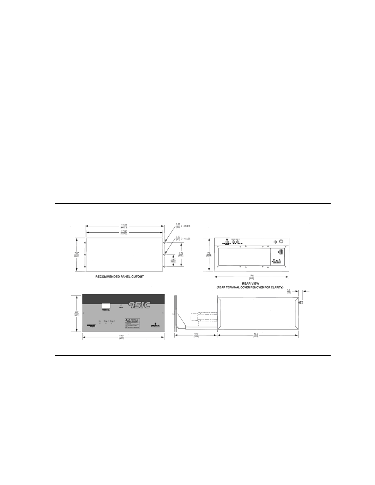
2.2 Location
Install analyzer in a clean area, free from moisture and excessive vibration, at a stable
temperature within 4 to 40° C.
Figure 2-1: Panel Cutout / Installation Drawing
The analyzer should be mounted near the sample source to minimize sample transport
time.
2-1

Instruc tion Manual Rosemo unt Analyt ical
748214-W SEPTEMBER 2010
A temperature control system maintains the internal analyzer temperature at 50° C (122°
F) to ensure proper operation over an ambient temperature range of 4 to 40° C (40 to
104° F). Temperatures outside these limits necessitate the use of special temperature
controlling equipment or environmental protection. Also, the ambient temperature
should not change at a rate exceeding 10° C per hour.
The cylinders of air and span gas should be located in an area of constant ambient
temperature.
2.3 Voltage requirements
WARNING
ELECTRICAL SHOCK HAZARD
For safety and proper performance this instrument must be connected to a properly grounded three-
wire source of power.
This instrument was shipped from the factory pre-configured to operate on 115 VAC, 50/
60 Hz electric power.
2-2

Ro semoun t Analyti cal Ins tru ction M anual
SEPTEMBER 2010 748214-W
2.3.1 Operating on 230 VAC
To operate the analyzer on 230 VAC, 50/60 Hz, do the following:
1. Set the voltage select switches (S1, S2, S3) on the Power Supply Board and the
voltage select switch (S3) on the Temperature Control Board to the 230 VAC
position.
Figure 2-2: Power Supply Board voltage select switches
Figure 2-3: Temperature Control board voltage select switch
S3
2-3

Instruc tion Manual Rosemo unt Analyt ical
748214-W SEPTEMBER 2010
2. On the rear of the analyzer, replace the 6.25 A fuse with the 3.15 A fuse (P/N
898587) that is provided in the shipping kit.
Figure 2-4: Rear view of Model 951C (cover removed)
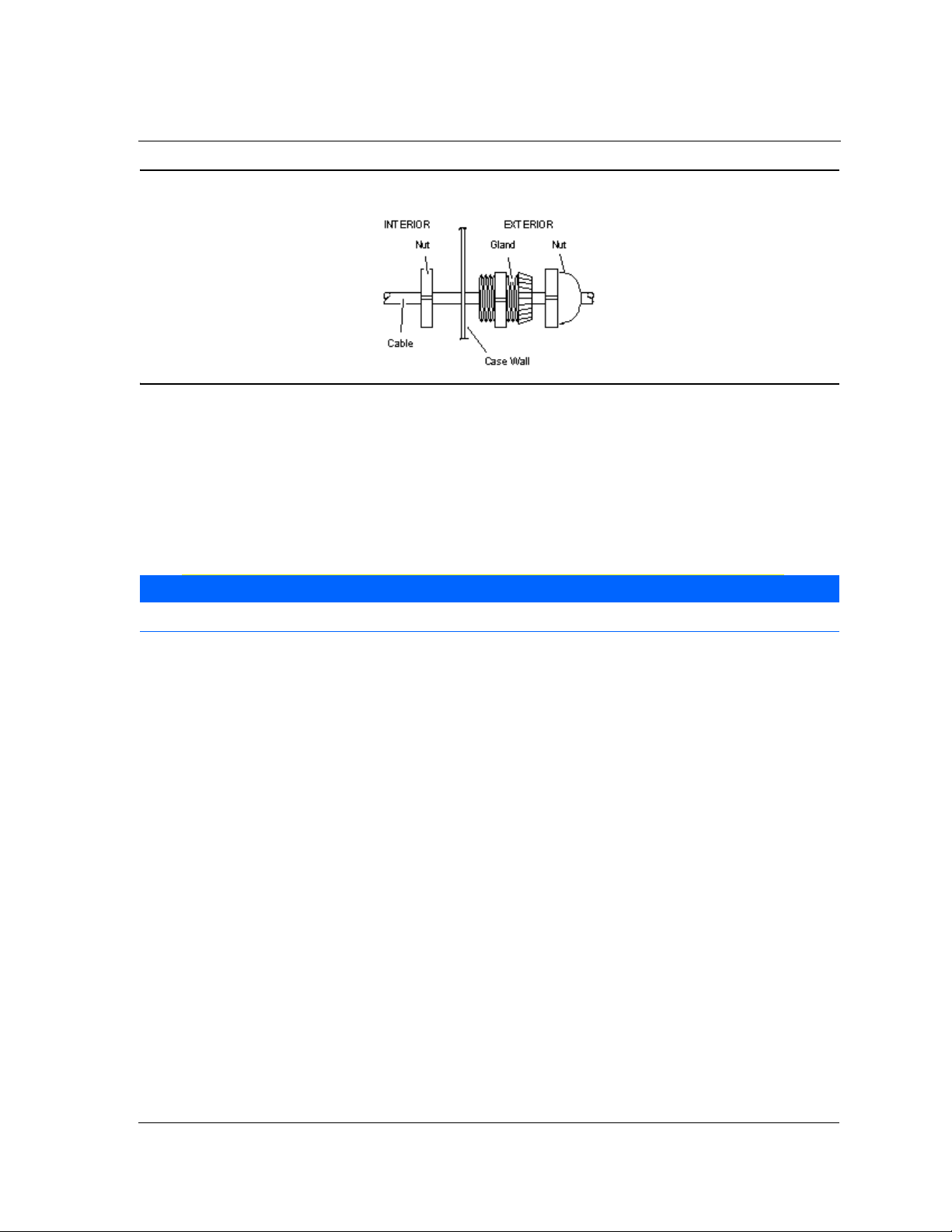
2.4 Connecting cables
The power (PN# 899330) and recorder (PN# 899329) cable glands are supplied in the
shipping kit. To connect the appropriate cable to its connector or terminal strip on the
analyzer, do the following:
1. Remove the analyzer’s rear cover to access the terminals.
2. Route each cable through its cable gland and connect to the appropriate connector
or terminal strip.
2-4
Ro semoun t Analyti cal Ins tru ction M anual
SEPTEMBER 2010 748214-W
Figure 2-5: Cable gland
3. Tighten the glands.
2.4.1 Connecting the power cord
If this instrument is located on a bench or table top or is installed in a protected rack,
panel or cabinet, power can be connected with a 3-wire flexible power cord.
NOTE
The power cord must be atleast 18 AWG with a maximum outside diameter (OD) of .48 inches.
To connect the power cord to the Model 951C, do the following:
1. Using the cable gland (PN# 899330) that is provided in the installation kit, insert
the power cord through the hole on the Model 951C that is labeled POWER.
2. Connect the power cord leads to TB1 on the rear panel.
3. Tighten the cable gland adequately to prevent the rotation or slippage of the power
cable. Since the rear terminals do not slide out with the chassis, no excess power
cable slack is necessary.
2-5

Instruc tion Manual Rosemo unt Analyt ical
748214-W SEPTEMBER 2010
The following power cord and/or support feet are available:
• Power cord (PN# 634061), which contains a 10-foot North American power cord
set.
• Enclosure Support Kit (PN# 634958), which contains four enclosure support feet for
bench top use.
• Power Cord/Enclosure Support Kit (PN# 654008), which contains a 10-foot North
American power cord set and four enclosure support feet.
NOTE
If the instrument is permanently mounted in an open panel or rack, use electrical metal tubing or conduit.
2.4.2 Connecting the potentiometric recorder cables
Potentiometric recorder cables connect to the rear panel. Route the cable through the
cable gland in the hole on the Model 951C that is labeled RECORDER OUTPUT and
connect the cable’s leads tothe VOLT OUTPUT terminals.
Table 2-1. Potentiometric cable specifications
Distance from recorder to analyzer: 1000 feet (305 meters) maximum
Input impedance: Greater than 2000 ohms
Cable (user supplied): Two conductor, shielded, min. 20 AWG
Voltage output: 0 to +5 VDC
2-6

Ro semoun t Analyti cal Ins tru ction M anual
SEPTEMBER 2010 748214-W
2.4.3 Connecting the current recorder
Current recorder cables connect to the rear panel. Route the cable through the cable
gland in the hole on the Model 951C that is labeled RECORDER OUTPUT and connect the
cable’s leads to the CUR OUTPUT terminals.
Table 2-2. Recorder cable specifications
Distance from recorder to analyzer: 3000 feet (915 meters).maximum
Load resistance: Less than 700 Ohms
Cable (user supplied): Two conductor, shielded, min. 20 AWG
Voltage output: 0 to +5 VDC
2.4.4 Adjusting the current output to produce a zero of 0 mA
Do the following to adjust the current output to produce a zero of 0 mA:
1. Do the following to establish the correct zero gas pressure:
a. Supply zero gas to rear panel sample inlet.
b. Note the reading on internal sample pressure gauge. It should be the same as
the nominal 4 psig (28 kPa) sample pressure indicated on the internal sample
pressure gauge.
c. The internal sample pressure should remain constant when the analyzer input
sample is switched from a calibration gas standard to a zero gas standard. This
can be assured by setting the delivery pressure from the sample gas cylinder
and the zero gas cylinder equal to the delivery pressure of the span gas
cylinder, which is 20 psig (138 kPa). If this cannot be accomplished, adjust the
output pressure regulator on the zero gas cylinder as required.
2. Adjust R23, the zero adjust potentiometer on the power supply board, to produce 0
mA current output.
2-7

Instruc tion Manual Rosemo unt Analyt ical
748214-W SEPTEMBER 2010
2.5 Gas requirements
The instrument requires two gases normally supplied from cylinders: air and span gas.
2.5.1 Air (U.S.P. Breathing Grade)
Air is used as both an oxygen source for the generation of the ozone required for the
chemiluminescence reaction, and as a standard gas for zero calibration. Air for each
purpose must be supplied from a separate cylinder due to the different pressure
requirements at the ozonator and the zero inlets.
2.5.2 Span Gas
Span gas is a standard gas of accurately known composition that is used to set an upscale
calibration point. The usual span gas is NO or NO2 in a background of nitrogen.
WARNING
HIGH PRESSURE GAS CYLINDERS
The Model 951C requires periodic calibration with a span gas. “Calibrating the analyzer” on page 3-10.
See also General Precautions for Handling and Storing High Pressure Gas Cylinders, page P-5.
NOTE
For maximum calibration accuracy, the concentration of nitrogen oxide in the span gas should be similar to
that in the sample gas. Also, the span gas should be supplied to the Model 951C’s rear panel sample inlet
at the same pressure as the sample gas. To ensure constant pressure, use a pressure regulator immediately
upstream from the sample inlet.
Each span gas used should be supplied from a tank or cylinder equipped with a clean,
noncorrosive, two-stage regulator. In addition, a shut off valve is recommended.
Install the gas cylinders in an area of relatively constant ambient temperature.
2-8
 Loading...