


Rosemount Analytical
ODEL
M
XPLOSION PROOF
E
815
ON
N
NSTRUCTION MANUAL
I
ISPERSIVE INFRARED
-D
NALYZER
A
748175-F

Notice
Information contained in this document is subject to change without notice.
Irtran™ is a trademark of Eastman Kodak Co.
Pyrex® is a registered trademark of Corning Glass Works.
Teflon® and Viton® are registered trademarks of E.I. du Pont de Nemours & Co., Inc.
Manual Part Number 748175-F
October 1997
Rosemount Analytical
4125 East La Palma Avenue
Anaheim, California 92807-1802

C
ONTENTS
P
REFACE
PURPOSE/SAFETY SUMMARY........................................................................P-1
SPECIFICATIONS..............................................................................................P-3
CUSTOMER SERVICE, TECHNICAL ASSISTANCE AND FIELD SERVICE ....P-4
RETURNING PARTS TO THE FACTORY..........................................................P-4
TRAINING ......................................................................................................P-4
DOCUMENTATION............................................................................................P-4
COMPLIANCES..................................................................................................P-5
S
ECTION
1.1 GENERAL DESCRIPTION.......................................................................1-1
1.2 APPLICATIONS........................................................................................1-1
1.3 AVAILABLE OPTIONS..............................................................................1-2
S
ECTION
2.1 UNPACKING..............................................................................................2-1
2.2 LOCATION.................................................................................................2-1
2.3 VOLTAGE REQUIREMENTS....................................................................2-1
2.4 ELECTRICAL CONNECTIONS ................................................................2-2
2.5 SAMPLE CONNECTIONS........................................................................2-2
2.6 CALIBRATION GAS CONNECTIONS AND REQUIREMENTS................2-2
2.7 SAMPLE HANDLING SYSTEM................................................................2-3
2.8 LEAK TEST...............................................................................................2-5
1. I
NTRODUCTION
2. U
2.4.1 Line Power Connections .............................................................2-2
2.4.2 Recorder Connections.................................................................2-2
NPACKING AND INSTALLATION
2.9 OPTIONS..................................................................................................2-6
748175-F Rosemount Analytical October 1997
Model 815 Explosion Proof Non-Dispersive Infrared Analyzer
i

C
ONTENTS
S
ECTION
S
ECTION
3.1 LEAK TEST..............................................................................................3-1
3.2 POWER VERIFICATION..........................................................................3-1
3.3 OPERATING CONTROLS AND INDICATORS........................................3-2
3.4 CALIBRATION ..........................................................................................3-3
2. (
2.9.1 Air Purge Kit 652271...................................................................2-6
2.9.2 Current Output Kit 652269..........................................................2-6
2.9.3 Case Heater Temperature Control Kit 652270............................2-7
2.9.4 Linearizer Kit 652268..................................................................2-8
2.9.5 Motor/Source Assembly Purge Kit 655094.................................2-10
3. I
3.3.1 Digital Display.............................................................................3-2
3.3.2 MODE Switch.............................................................................3-2
3.3.3 ZERO Adjustment.......................................................................3-2
3.3.4 SPAN Adjustment.......................................................................3-2
3.4.1 Calibration Procedure.................................................................3-4
3.4.2 Linearizer Board Calibration.......................................................3-4
3.4.3 Calibration Curve Construction...................................................3-5
CONTINUED
NITIAL STARTUP AND CALIBRATION
)
3.5 LINEARIZATION PROCEDURE ..............................................................3-7
3.6 CURRENT OUTPUT................................................................................3-9
S
ECTION
4.1 ROUTINE OPERATION............................................................................4-1
4.2 RECOMMENDED CALIBRATION FREQUENCY.....................................4-1
4.3 SHUTDOWN.............................................................................................4-1
4.4 DETECTION SYSTEM THEORY............................................................. 4-2
4.5 ELECTRONIC CIRCUITRY ...................................................................... 4-3
4. R
4.5.1 Oscillator Circuit Board (Schematic 623995) and
4.5.2 Functioning of Modulation System in TUNE Mode ..................... 4-3
4.5.3 Functioning of Modulation System in Operating Mode...............4-3
4.5.4 Radio-Frequency Demodulator................................................... 4-4
4.5.5 Signal Board (Schematic 652431)..............................................4-4
4.5.6 Power Supply Board (Schematic 624073)..................................4-5
4.5.7 Case Heater Temperature Control Board (Schematic 624003)..4-5
4.5.8 Current Output Board (Schematic 652439) ................................4-5
4.5.9 Linearizer Board (Schematic 624674)........................................4-5
OUTINE OPERATION AND THEORY
Associated Elements of Amplitute Modulation Circuit... 4-3
ii
October 1997 Rosemount Analytical 748175-FModel 815 Explosion Proof Non-Dispersive Infrared Analyzer

C
ONTENTS
S
ECTION
5.1 SYMPTOM CHART ..................................................................................5-1
5.2 TEST EQUIPMENT ..................................................................................5-2
5.3 VOLTAGE CHECKS.................................................................................5-2
5.4 OSCILLATOR TUNE ADJUSTMENT .......................................................5-2
5.5 PREAMP GAIN.........................................................................................5-2
5.6 SOURCE BALANCE SHUTTER ADJUSTMENT......................................5-4
5.7 SOURCE ALIGNMENT.............................................................................5-6
5.8 SOURCE CURRENT ADJUSTMENT.......................................................5-6
5.9 TIME CONSTANT.....................................................................................5-6
5.10 CASE HEATER TEMPERATURE CONTROL ASSEMBLY......................5-7
S
ECTION
6.1 CELL REMOVAL, CLEANING AND REPLACEMENT..............................6-2
5. T
5.5.1 Peak Adjustment.........................................................................5-4
6. R
6.1.1 Long Cell Configurations.............................................................6-2
6.1.2 Short Cell Configurations ............................................................6-2
ROUBLESHOOTING
OUTINE SERVICING
6.2 CELL DESICCANT...................................................................................6-4
6.2.1 Desiccant Replacement..............................................................6-4
6.3 SOURCE REPLACEMENT.......................................................................6-5
6.4 CHOPPER MOTOR ASSEMBLY..............................................................6-6
6.4.1 Long Cell Configurations.............................................................6-6
6.4.2 Short Cell Configurations ............................................................6-6
6.5 DETECTOR REPLACEMENT..................................................................6-7
6.5.1 Removal - Long Cell Configurations............................................6-7
6.5.2 Removal - Short Cell Configurations...........................................6-7
6.5.3 Detector Installation.....................................................................6-8
S
ECTION
7.1 CIRCUIT BOARD REPLACEMENT POLICY.............................................7-1
7.2 SELECTED REPLACEMENT PARTS .......................................................7-2
7.3 OPTION KITS...........................................................................................7-2
7. R
7.2.1 Model 815 Common Parts...........................................................7-2
7.2.2 Optical Bench..............................................................................7-2
7.3.1 Linearizer Kit PN 652268 ...........................................................7-2
7.3.2 Current Output Kit PN 652269 ....................................................7-2
EPLACEMENT PARTS
748175-F Rosemount Analytical October 1997
Model 815 Explosion Proof Non-Dispersive Infrared Analyzer
iii

C
ONTENTS
S
ECTION
NFRARED CALIBRATION AND DATA SHEET (PER APPLICATION
I
ENERAL PRECAUTIONS FOR HANDLING
G
ARRANTY
W
IELD SERVICE AND REPAIR FACILITIES
F
F
IGURES
1-1 Model 815 Explosion Proof NDIR Analyzer..............................................1-1
2-1 Model 815 Component Locations.............................................................2-3
2-2 Power Supply Board.................................................................................2-4
2-3 Case Heater Temperature Control Board.................................................2-4
2-4 Current Output Board...............................................................................2-7
2-5 Installation of Current Output and Temperature Control Options.............2-8
2-6 Linearizer Board.......................................................................................2-9
2-7 Signal Board with Linearizer Board Installed............................................2-9
3-1 Model 815 Operating Controls and Indicators..........................................3-3
3-2 Signal Board Component Locations.........................................................3-5
3-3 Linearizer Board Adjustments..................................................................3-6
3-4 Typical Linearization Curve......................................................................3-7
3-5 Current Output Board...............................................................................3-9
4-1 NDIR Detection System...........................................................................4-2
4-2 Functional Block Diagram ........................................................................4-6
5-1 Modulation System ................................................................................... 5-5
6-1 Optical Bench...........................................................................................6-3
6-2 Motor/Source Assembly...........................................................................6-6
6-3 Detector Replacement..............................................................................6-9
7-1A Configurations 06, 07, 19, 21, 31, 36, 41, 45, 54, 71, 72, 81....................7-4
7-1B Configurations 35, 73................................................................................7-4
7-1C Configurations 64, 83................................................................................7-5
7-2A Configurations 08, 10, 12, 13, 18, 32, 39, 42, 43, 55, 63, 65, 67..............7-5
7-2B Configurations 22, 23, 29, 30, 33, 34, 38, 76............................................7-6
7-2C Configuration 26.......................................................................................7-6
7-2D Configurations 74, 82, 84..........................................................................7-7
7-3 Case Heater Temperature Control Assembly...........................................7-10
7. (
CONTINUED
7.3.3 Case Heater Temperature Control Kit PN 652270......................7-3
7.3.4 Air Purge Kit PN 652271............................................................7-3
7.3.5 Motor/Source Purge Kit PN 655094............................................7-3
)
)
TORING HIGH PRESSURE CYLINDERS
& S
iv
October 1997 Rosemount Analytical 748175-FModel 815 Explosion Proof Non-Dispersive Infrared Analyzer

T
ABLES
3-1 Typical Linearization Calibration Values...................................................3-8
3-2 Linearization Calibration Values ...............................................................3-9
5-1 Troubleshooting Chart..............................................................................5-3
6-1 Types of Desiccant...................................................................................6-5
7-1 Configuration Figure List...........................................................................7-3
7-2 Optical Bench Components by Configuration...........................................7-7
C
ONTENTS
D
RAWINGS (LOCATED IN REAR OF MANUAL
623995 Schematic Diagram, Oscillator Board
624003 Schematic Diagram, Temperature Control Board
624073 Schematic Diagram, Power Supply Board
624674 Schematic Diagram, Linearizer Board
652258 Installation Drawing, Model 815
652259 Pictorial Wiring Diagram, Model 815
652431 Schematic Diagram, Signal Board
652439 Schematic Diagram, Current Output Board
652446 Schematic Diagram, Zero/Span Control Board
)
748175-F Rosemount Analytical October 1997
Model 815 Explosion Proof Non-Dispersive Infrared Analyzer
v

C
ONTENTS
N
OTES
vi
October 1997 Rosemount Analytical 748175-FModel 815 Explosion Proof Non-Dispersive Infrared Analyzer

P
REFACE
P
URPOSE/SAFETY SUMMARY
To avoid explosion, loss of life, personal injury and damage to this equipment and on-site
property, all personnel authorized to install, operate and service the Model 815 Explosion
Proof Non-Dispersive Infrared Analyzer should be thoroughly familiar with and strictly
follow the instructions in this manual.
If this equipment is used in a manner not specified in these instructions, protective
systems may be impaired.
Save these instructions.
DANGER
personal injury, death, or substantial property damage if the warning is ignored.
WARNING
personal injury, death, or substantial property damage if the warning is ignored.
CAUTION
personal injury or property damage if the warning is ignored.
NOTE
important but not hazard-related.
is used to indicate the presence of a hazard which
is used to indicate the presence of a hazard which
is used to indicate the presence of a hazard which
is used to indicate installation, operation or maintenance information which is
will
cause
can
cause
will or can
cause
severe
severe
minor
WARNING: ELECTRICAL SHOCK HAZARD
Do not operate without doors and covers secure. Servicing requires access to
live parts which can cause death or serious injury. Refer servicing to qualified
personnel.
For safety and proper performance this instrument must be connected to a
properly grounded three-wire source of power.
This instrument is shipped from the factory set up to operate on 115 volt, 50/60
Hz electric power. For operation on 230 volt, 50/60 Hz power, see Section 2.3
and Figures 2-2 and 2-3 for modifications.
748175-F Rosemount Analytical October 1997
Model 815 Explosion Proof Non-Dispersive Infrared Analyzer
P-1
P
REFACE
WARNING: POSSIBLE EXPLOSION HAZARD
This analyzer is of a type capable of analysis of sample gases which may be
flammable. If used for analysis of such gases the instrument explosion-proof
enclosure must be suitable for the gas.
WARNING: EXPLOSION HAZARD
If explosive gases are introduced into this analyzer, the sample containment
system must be carefully leak-checked upon installation and before initial
startup, during routine maintenance and any time the integrity of the sample
containment system is broken, to ensure the system is in leak-proof condition.
Leak-check instructions are provided in Section 2.8.
Do not operate the Model 815 Explosion-Proof Analyzer without lens cover and
door in place with all bolts secured, unless location has been determined to be
non-hazardous.
WARNING: HIGH PRESSURE GAS CYLINDERS
This analyzer requires periodic calibration with known zero and standard gases.
Refer to General Precautions for Handling and Storing High Pressure Cylinders,
in the rear of this manual.
WARNING: PARTS INTEGRITY
Tampering or unauthorized substitution of components may adversely affect
safety of this product. Use only factory documented components for repair.
P-2
October 1997 Rosemount Analytical 748175-FModel 815 Explosion Proof Non-Dispersive Infrared Analyzer

S
PECIFICATIONS
P
REFACE
P
OWER REQUIREMENTS
A
MBIENT TEMPERATURE
D
IMENSIONS
W
EIGHT
E
NCLOSURE
S
IGNAL OUTPUT
R
EPEATABILITY
N
Z
S
:
OISE
ERO DRIFT
PAN DRIFT
:
:
:
:
:
1
:
1
:
120/220 VAC ±10%, 50/60 ±3 Hz, 150 W;
:
350 W with optional case heater
32°F to 113°F (0°C to 45°C)
:
Some configurations may require optional case heater for temperatures
outside 59°F to 95°F (15°C to 35°C). Refer to Appendix A.
21.5 in (55.0 cm) H
15.5 in. (39 cm) W
11.8 in. (30 cm) D
119 lbs (54 kg)
Explosion Proof, Class I, Groups B,C,D, Division 1.
Mount in weather protected area.
Standard: 0-5 VDC (0-1 VDC field selectable on board)
Optional: 4-20 mA or 0-20 mA (field selectable), 750 ohms max.
1% of fullscale
1% of fullscale
±
1% of fullscale per 24 hours
±
1% of fullscale per 24 hours
R
ESPONSE TIME
(ELECTRONIC
S
AMPLE CELL LENGTH
R
EFERENCE
M
ATERIALS IN CONTACT
S
WITH
WINDOWS
CELLS
TUBING
FITTINGS
S
1
Performance specifications based on ambient temperature shifts of less than 20°F (11°C) per hour.
AMPLE
AMPLE PRESSURE
:
)
:
:
:
:
:
:
:
Variable, 90% of fullscale in 1 sec to 10 sec, field selectable. (Application
dependent)
0.04 in. (1 mm) to 10.0 in. (254 mm)
:
Sealed
Sapphire, quartz, Irtran
Gold plated Pyrex or stainless steel
FEP Teflon
316 stainless steel
Max 10 psig (69 kPa), standard
748175-F Rosemount Analytical October 1997
Model 815 Explosion Proof Non-Dispersive Infrared Analyzer
P-3

P
REFACE
C
USTOMER SERVICE
For order administration, replacement Parts, application assistance, on-site or factory
repair, service or maintenance contract information, contact:
R
ETURNING PARTS TO THE FACTORY
Before returning parts, contact the Customer Service Center and request a Returned
Materials Authorization (RMA) number. Please have the following information when
you call:
Number.
Prior authorization by the factory must be obtained before returned materials will be
accepted. Unauthorized returns will be returned to the sende r, f re ight collect.
When returnin g any pro duct o r compon ent t hat has be en expo sed to a toxic, corrosi ve
or other hazardous material or used in such a hazardous environment, the user must
attach an appropriate Material Safety Data Sheet (M.S.D.S.) or a written certification
that the material has been decontaminated, disinfected and/or detoxified.
Model Number, Serial Number, and Purchase Order Number or Sales Order
, T
ECHNICAL ASSIST ANCE AND FIELD SERVICE
Rosemount Analytical Inc.
Process Analytical Division
Customer Service Center
1-800-433-6076
Return to:
Rosemount Analytical Inc.
4125 East La Palma Avenue
Anaheim, California 92807
T
RAINING
A comprehensive Factory Training Program of operator and service classes is
available. For a copy of the
the Technical Services Depart men t at:
D
OCUMENTATION
The following Model 815 Explosion Proof Non-Dispersive Infrared Analyzer instruction
materials are available. Contact Customer Service or the local representative to
order.
748175 Instruction Manual (this document)
Current Operator and Service Training Schedule
Rosemount Analytical Inc.
Phone: 1-714-986-7600
FAX: 1-714-577-8006
contact
P-4
October 1997 Rosemount Analytical 748175-FModel 815 Explosion Proof Non-Dispersive Infrared Analyzer

C
OMPLIANCES
The Model 815 Explosion Proof Non-Dispersive Infrared Analyzer is approved by
Factory Mutual for use in Class I, Groups B, C and D Division 1 hazardous locations.
FM
P
REFACE
APPROVED
97-C209
748175-F Rosemount Analytical October 1997
Model 815 Explosion Proof Non-Dispersive Infrared Analyzer
P-5

P
REFACE
N
OTES
P-6
October 1997 Rosemount Analytical 748175-FModel 815 Explosion Proof Non-Dispersive Infrared Analyzer

I
NTRODUCTION
1
1.1 GENERAL DESCRIPTION
The Model 815 Non-Dispersive Infrared Analyzer is designed to continuously monitor
the concentration of a particular infrared absorbing component of interest in a flowing
gaseous mixture. Concentration is displayed as a percent of fullscale. Signal outputs
of 0-5 VDC or 0-1 VDC are field selectable standard.
The Analyzer enclosure is designed to meet the requirements for Class I, Division 1,
Groups B, C, and D, per the National Electrical Code (ANSI/NFPA 70), and should be
mounted in a weather-protected area.
1.2 APPLICATIONS
Monitoring applications are found in the Application Data Sheet which is available from
the local sales office (see page P-4).
IGURE
F
748175-F Rosemount Analytical October 1997
1-1. M
ODEL
815 E
XPLOSION PROOF
ZERO SPAN
DETECTOR RANGE 1
TUNE RANGE 2
Rosemount Analytical
Model 815
Oxygen Analyzer
NDIR A
Model 815 Explosion Proof Non-Dispersive Infrared Analyzer
NALYZER
1-1

I
NTRODUCTION
Some sample streams contain various other infrared-absorbing substances, other than
the component of interest. To minimize interference in such applications, the
instrument may incorporate an optical filter and, if necessary, a sealed filter cell
containing an appropriate gas charge, as noted in the Factory Calibration and Data
Sheet located in the rear of this manual.
1.3 AVAILABLE OPTIONS
Operation of the Model 815 can be enhanced with the choice of several options, all of
which can be installed in the field after the analyzer has been ordered.
IGNAL LINEARIZER
S
A signal linearizer kit is available for each range. Linearizers enable the operator to
convert non-linear output signals into linear output signals.
SOLATED CURRENT OUTPUT
I
The current output option can be field set for either 4-20mA or 0-20mA, corresponding
to 0% to 100% of fullscale. Maximum load is 750 ohms.
ASE TEMPERATURE CONTROLLER
C
A proportional temperature controller, with heater and fan assembly, maintains proper
operating temperature inside the case.
IR PURGE
A
The air purge kit is to be installed with user-supplied components. It is designed for
use in cases where a corrosive gas is either flowing through the cell or is present in
the environment. The air purge option is provided for protection of the instrument only,
and is not intended as a safety feature for use in a hazardous area.
OTOR/SOURCE ASSEMBLY PURGE
M
This purge is recommended in some applications to provide a CO2 free, spectrally
constant atmosphere within the Motor/Source Assembly.
AMPLE HANDLING SYSTEM ACCESSORY
S
If so ordered, an associated sample-handling system may be either factory-assembled
or supplied for field installation, depending on ordering instructions. Sampling systems
are designed on the basis of information furnished by the customer, which includes a
complete stream analysis. Refer to the Factory Calibration and Data Sheet for
information on the sample handling sy stem.
1-2
October 1997 Rosemount Analytical 748175-FModel 815 Explosion Proof Non-Dispersive Infrared Analyzer

U
NPACKING AND INSTALLATION
2
2.1 UNPACKING
Carefully examine the shipping carton and contents for signs of damage. Immediately
notify the shipping carrier if the carton or its contents are damaged. Retain the carton
and packing material until the instrument is operational
2.2 LOCATION
Locate the analyzer in a weather-protected location free from vibration. For best
results mount the analyzer near the sample stream to minimize sample-transport time.
Refer to Installation Drawing 652258.
If equipped with P/N 652271 air purge, refer to Section 2.9.1. The air purge is
designed to provide a corrosion-free or spectrally-constant internal atmosphere, and
not intended to provide explosion hazard protection.
is
2.3 VOLTAGE REQUIREMENTS
WARNING: ELECTRICAL SHOCK HAZARD
For safety and proper performance, this instrument must be connected to a
properly grounded three-wire source of electrical power.
Verify that power switch settings are set for the power available at the site (115 VAC or
220 VAC).
Analyzers are shipped from the factory set for 120 VAC, 50/60 Hz operation. To
convert to 220 VAC, 50/60 Hz power, position voltage select switches S1, S2 (located
on Power Supply Board, Figure 2-2), and S3 (located on the optional Case Heater
Temperature Control Board, Figure 2-3), to the 230 VAC position.
Power consumption is less than 150 watts without optional case heater; 350 watts with
optional case heater installed.
748175-F Rosemount Analytical October 1997
Model 815 Explosion Proof Non-Dispersive Infrared Analyzer
2-1

U
NPACKING AND INSTALLATION
2.4 ELECTRICAL CONNECTIONS
2.4.1 L
2.4.2 R
INE POWER CONNECTIONS
Refer to Figures 2-1 and 2-5, Installation Drawing 652258 and Pictorial Wiring
Diagram 652559.
Route the power cable (customer supplied 3-wire, minimum 18 AWG) through the
power conduit opening in the bottom of the instrument.
Connect to power terminal block TB1 as follows:
HOT/L1 = TB1-1
NEUTRAL/L2 = TB1-2
GROUND = TB1-3 or TB1-4
ECORDER CONNECTIONS
Refer to Figure 2-1 and 2-5, Installation Drawing 652258 and Pictorial Wiring Diagram
652559.
Route the cable (customer supplied 2-wire shielded cable) through the signal output
conduit opening at the bottom of the enclosure.
Connect to recorder output/curr ent out put terminal block TB2 as follows:
(+)OUTPUT = TB2-1
(- ) OUTPUT = TB2-2
SHIELD (GND) = TB2-3
2.5 SAMPLE CONNECTIONS
Refer to Figure 2-1 and Installation Drawing 652258. Connect sample gas tubing to
the Model 815 through the 1/4-inch ferrule type compression fittings located on the
bottom of the enclosure.
2.6 CALIBRATION GAS CONNECTIONS AND REQUIREMENTS
Refer to Figure 2-1 and Installation Drawing 652258.
Zero and span gases are to be connected to the same inlet fitting as the sample gas.
All applications require a zero standard gas to set the baseline point on the digital
display or output signal. Refer to the Calibration and Data Sheet. Use the background
gas as the zero gas. If a background gas is not specified, use dry nitrogen for the zero
gas.
Span gas concentration is normally between 80% and 100% of the fullscale range the
analyzer will be set on. The background gas is also indicated on the Calibration and
Data Sheet. If no background gas is specified, use dry nitrogen.
2-2
October 1997 Rosemount Analytical 748175-FModel 815 Explosion Proof Non-Dispersive Infrared Analyzer

U
NPACKING AND INSTALLATION
2.7 SAMPLE HANDLING SYSTEM
The Model 815 does not contain any filters in the sample flow system to prevent
contamination of the sample lines or cells.
The sample must be clean and kept above the dew point to minimize maintenance and
to prolong the life of the components in the sample flow system. Sample Handling
components and tubing must be constructed of materials compatible with the sample.
Contact the local representative or the factory if an additional sample handling system
is required.
Linearizer Board
(mounted on farside of Signal Board)
(see Figures 2-6 and 2-7)
Power Supply Board
(see Figure 2-2)
Transformer
Motor/Source Assembly
(see Figure 6-2)
Signal Board
(see Figure 2-7)
Span Potentiometer
Zero/Span
Control Board
MODE Switch
Zero Potentiometer
Current Output Board
(see Figure 2-4)
Signal Output
Case Air Purge Inlet
Power
AC Power Terminal
Block TB1
Sample Cell
Sensor, Case Heater
Temperature Control
(see Figure 2-5)
Reference Cell
Detector Assembly
(see Figure 6-3)
Case Heater Temperature Control
Assembly
(see Figure 7-3)
Recorder Output /Current Output
Term inal Block TB2
Fuse
IGURE
F
2-1. M
ODEL
815 C
OMPONENT LOCATIONS
748175-F Rosemount Analytical October 1997
Sample In
Sample Out
Flame Arrestor
Fitting 1/4 inch Tube Connec tor
Model 815 Explosion Proof Non-Dispersive Infrared Analyzer
2-3
U
NPACKING AND INSTALLATION
Set switch windows for voltage required
S2 S1
ADAPTER
1
J16
J12
115 115
TEMP
CONTROL
CASE
J5
1
R11
4 3 2 1
S2 S1
230V
115V
DETECTOR
HEATER
J4
1
K1
XFMER
FAN
J2
1
CR4
CR3
CR2
XFMER
C4
+
C2
+
C3
+
C1
S3
SS LUFT
+
+
+
+
VR4
VR3
TP1
R9
TP2
TP1
TP2
R12 R13
8
1
7
6
G
I
2
3
45
C6
+
C12
VR2
VR1
I
C8
G
O
I
G
O
+
+
C10
+
C11
C5
C7
+
C9
+
R1
R2
I
O
G
O
R3
R10
R8
R4
R5
R6
R7
AR1
- CR1 +
R9
C13
U1
+
+
R37
R34
R35
R36
R39
R18
C14
C18
C
E
Q3
1
AR4
C19
J
AR5
R17
CR8
R25
R29
R26
E
C
AK
G
R21
R22
10
C21
J14
1
R
38
1
J11
J8
1
B
Q2
C15
+
J15
R24
R23
1
Q1
1
J13
Q4
U2
R19
R20
R16
R15
C20
C16
R31
R30
R27
R28
R32
R33
B
CR6
CR7
R14
CR5
J7
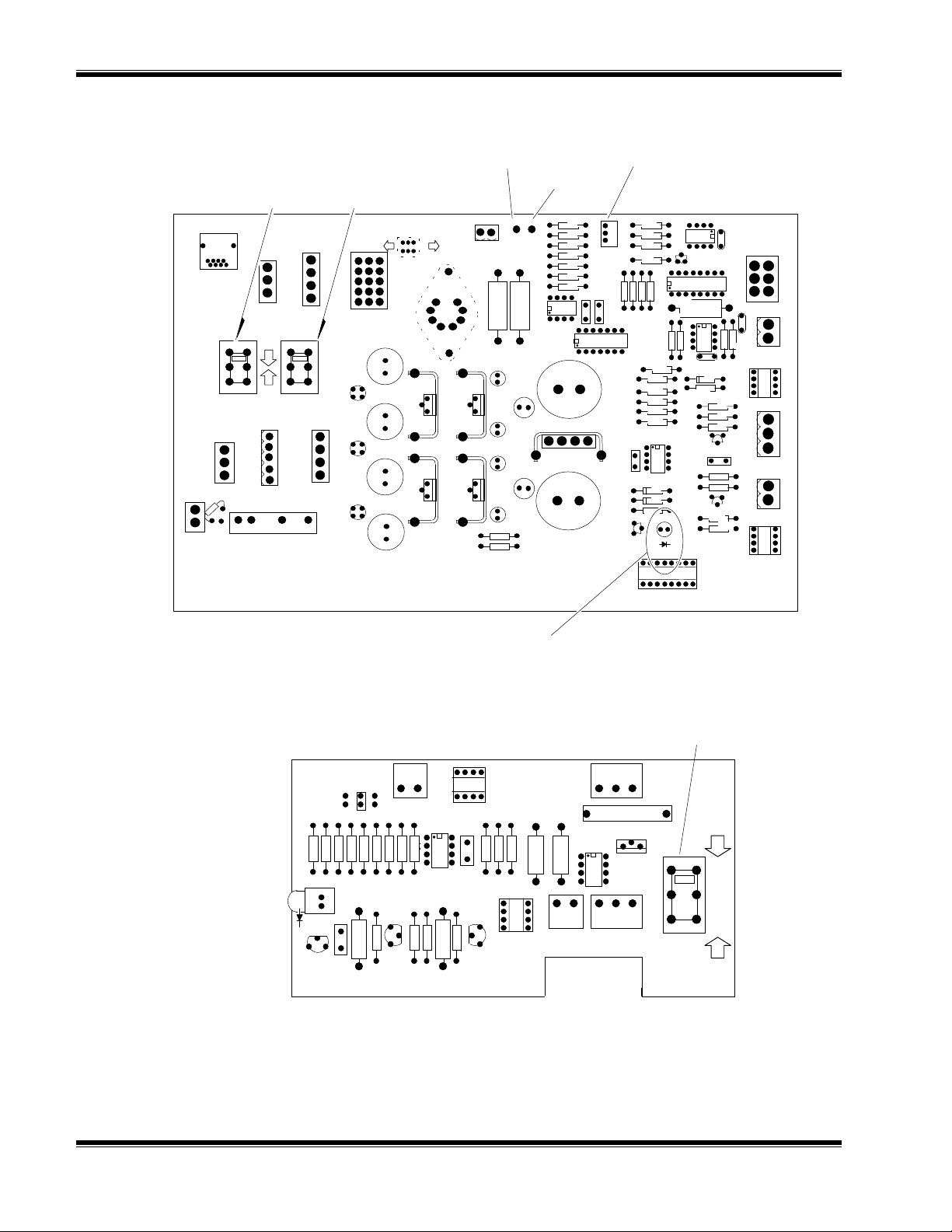
IGURE
F
IGURE
F
2-2. P
OWER SUPPLY BOARD
SENSOR J18 POWER
400A 880 951E
R10 R11 R7 R8
C2
CR1
R4
C1
C
E
B
+
Q2
Set switch window for voltage required
2-3. C
ASE HEATER TEMPERATURE CONTROL BOARD
Heater LED (CR5)
R17R16 R12CR2
R3
1
AR1
R13
R2R1
Q1
K
G
A
TEMP CONTROL BD
S3
J11
J19
TEST
POWER
LINE
J5
R15
R14
1 2 1 2 3
T.I.F. HEATER
C4
3 2 1
U2
1
2
3
1
U1
S3
230
115
J17
115
SUPPLY
R6
C3
R9 R5
CR3
1
E
B
Q3
C
2-4
October 1997 Rosemount Analytical 748175-FModel 815 Explosion Proof Non-Dispersive Infrared Analyzer

U
NPACKING AND INSTALLATION
2.8 LEAK TEST
Any leakage must be corrected before introduction of sample and/or application of
electrical power.
WARNING: POSSIBLE EXPLOSION HAZARD
This analyzer is of a type capable of analysis of sample gases which may be
flammable. If used for analysis of such gases the instrument explosion-proof
enclosure must be suitable for the gas.
If explosive gases are introduced into this analyzer, the sample containment
system must be carefully leak-checked upon installation and before initial
startup, during routine maintenance and any time the integrity of the sample
containment system is broken, to ensure the system is in leak-proof condition.
Leak-check instructions are provided in this section.
Internal leaks resulting from failure to observe these precautions could result in
an explosion causing death, personal injury or property damage.
The following test is designed for sample pressure up to 10 psig (69 kPa).
1. Connect air (or other inert gas such as nitrogen) at 10 psig (69 kPa) to analyzer via
a flow indicator and set flow rate to fullscale at the sample inlet (unless otherwise
specified by the Calibration and Data Sheet.
2. Seal off sample outlet with a cap while air or inert gas is flowing into the sample
inlet. If the flowmeter reading drops to zero, the system is leak free. If the
flowmeter does not drop to zero, a leak in the system is present and must be
located and sealed before operating the Model 815.
Note:
Whether or not a leak is suspected, the sample flow system should be leak
checked under pressure before the analyzer is placed in operation.
3. Refer to the note below, then liberally cover the outlet plug and all gas connections
with a suitable test liquid such as SNOOP (PN 837810) to detect leaks. Apply to all
fittings, seals, and other possible leak sources. Bubbling or foaming indicates
leakage, but the absence of bubbles does not necessarily indicate that no leaks
exist.
4. If a flow is indicated, a leak is present and may be in an area that is inaccessible to
SNOOP. Continue leak testing and tighten all connections until the flow rate drops
to zero.
748175-F Rosemount Analytical October 1997
Model 815 Explosion Proof Non-Dispersive Infrared Analyzer
2-5

U
NPACKING AND INSTALLATION
Note:
Do not allow test liquid to contaminate cells, detector or source windows.
Should this occur, the cells should be cleaned (Section 6.1).
2.9 OPTIONS
The following options may be ordered as kits and installed in the field:
2.9.1 A
IR PURGE KIT
652271
WARNING: POSSIBLE EXPLOSION HAZARD
If an air purge is used, the purge inlet fitting must be equipped with a Flame
Arrestor Assembly (PN 638426) to prevent propagation of a flame or explosion
from inside the enclosure to the ambient atmosphere.
All precautions relating to the installation and operation of this instrument must
be strictly adhered to whether or not the air purge option is installed.
purge option is not intended as protection from explosion in hazardous areas.
Purging of the enclosure of the explosion-proof Model 815 may be recommended in
some applications to provide a corrosion free internal atmosphere. If the instrument is
to be equipped with an optional Air Purge Kit, refer to instruction sheet (748184)
supplied in kit for installation. This kit is designed to provide a corrosion free or
spectrally-constant internal atmosphere, and
hazard protection.
2.9.2 C
URRENT OUTPUT KIT
652269
is not intended to provide explosion
The air
2-6
Refer to Figures 2-1, 2-2, 2-4, 2-5, Pictorial Wiring Diagram 652259 and installation
Drawing 652258.
NSTALLATION
I
1. Mount the Current Output Board to the chassis next to the Power Supply Board
using the spacer and hex nut supplied in the kit.
2. Connect the two-wire cable supplied in kit (PN 749068) as follows:
Wire From To
Blue
Orange
Current Output Board
TB1-1 (-)
Current Output Board
TB1-2 (+)
Recorder Output/Current Output Terminal
Block TB2-5 (Current Output -)
Recorder Output/Current Output Terminal
Block TB2-4 (Current Output +)
October 1997 Rosemount Analytical 748175-FModel 815 Explosion Proof Non-Dispersive Infrared Analyzer

U
NPACKING AND INSTALLATION
3. Connect the eight conductor flat cable supplied in kit (PN 652257) from Current
Output Board J2 to Power Supply Board J9.
4. Refer to Section 3.6 for 4-20mA or 0-20mA adjustment procedur e.
2.9.3 C
ASE HEATER TEMPERATURE CONTROL KIT
652270
Refer to Figures 2-1, 2-2, 2-3, 2-5, 7-3 and Pictorial Wiring Diagram 652259.
NSTALLATION
I
1. Mount the Temperature Control Assembly to the chassis with the 4 screws
supplied in the kit.
2. Attach the sensor (at T.I.F. 2-position terminal block) to the reference cell with a
tie wrap as shown in Figure 2-1.
3. Connect the 3-conductor cable supplied in kit (PN 622903) from Temperature
Control Board J5 to Power Supply Board J5.
4. Connect the 8-conductor flat cable supplied in kit (PN 901768) from Temperature
Control Board J11 to Power Supply Board J11.
Baseline Current
Output Adjust
(0 or 4mA)
IGURE
F
Fullscale Current
Output Adjust
(20mA)
2-4. C
URRENT OUTPUT BOARD
ZERO
SPAN
C4
+
R7
CR2
R9
CR3
U6
R1
1
1
R2
U2
U1
U3
1 2 3 4
C5
+
+
C9
+
C8
+
C5
+
C7
C1
+
C2
+
U4
C3
MA
V/I 652442 BD
I G O
+ CR1
U5
TB1
-
+
J2
J1
1
O
G
I
To Power Supply Board
J12
To Recorder Output/Current
Output Terminal Block TB2
748175-F Rosemount Analytical October 1997
Model 815 Explosion Proof Non-Dispersive Infrared Analyzer
2-7
 Loading...