

Instruction Manual
748183-K
April 2002
Model 755
Oxygen Analyzer
http://www.processanalytic.com

ESSENTIAL INSTRUCTIONS
READ THIS PAGE BEFORE PROCEEDING!
Rosemount Analytical designs, manufactures and tests its products to meet many national and
international standards. Because these instruments are sophisticated technical products, you
MUST properly install, use, and maintain them to ensure they continue to operate within their
normal specifications. The following instructions MUST be adhered to and integrated into your
safety program when installing, using, and maintaining Rosemount Analytical products. Failure to
follow the proper instructions may cause any one of the following situations to occur: Loss of life;
personal injury; property damage; damage to this instrument; and warranty invalidation.
•
Read all instructions prior to installing, operating, and servicing the product.
If you do not understand any of the instructions, contact your Rosemount Analytical
•
representative for clarification.
•
Follow all warnings, cautions, and instructions marked on and supplied with the product.
•
Inform and educate your personnel in the proper installation, operation, and
maintenance of the product.
•
Install your equipment as specified in the Installation Instructions of the appropriate
Instruction Manual and per applicable local and national codes. Connect all products to
the proper electrical and pressure sources.
To ensure proper performance, use qualified personnel to install, operate, update, program,
•
and maintain the product.
When replacement parts are required, ensure that qualified people use replacement parts
•
specified by Rosemount. Unauthorized parts and procedures can affect the product’s
performance, place the safe operation of your process at risk, and VOID YOUR WARRANTY.
Look-alike substitutions may result in fire, electrical hazards, or improper operation.
•
Ensure that all equipment doors are closed and protective covers are in place, except
when maintenance is being performed by qualified persons, to prevent electrical shock
and personal injury.
The information contained in this document is subject to change without notice.
Teflon and Viton are registered trademarks of E.I. duPont de Nemours and Co., Inc.
Paliney No.7 is a trademark of J.M. Ney Co., Hartford, CT
SNOOP is a registered trademark of NUPRO Co.
Emerson Process Management
Rosemount Analytical Inc.
Process Analytic Division
1201 N. Main St.
Orrville, OH 44667-0901
T (330) 682-9010
F (330) 684-4434
e-mail: gas.csc@EmersonProcess.com
http://www.processanalytic.com

Model 755
PREFACE...........................................................................................................................................P-1
Definitions...........................................................................................................................................P-1
Intended Use Statement.....................................................................................................................P-2
Safety Summary .................................................................................................................................P-2
General Precautions For Handling And Storing High Pressure Gas Cylinders .................................P-4
Documentation....................................................................................................................................P-5
Compliances.......................................................................................................................................P-5
1.0 DESCRIPTION AND SPECIFICATIONS..............................................................................1-1
1-1 Overview................................................................................................................................1-1
1-2 Range Options.......................................................................................................................1-1
a. Standard Zero-Based Range Options ............................................................................1-1
b. Standard Zero-Suppressed Range Options ...................................................................1-3
c. Special Range Options ...................................................................................................1-3
1-3 Isolated Current Output Options............................................................................................1-3
1-4 Alarm Option..........................................................................................................................1-3
1-5 Case Mounting Options .........................................................................................................1-3
1-6 Electrical Options...................................................................................................................1-3
1-7 Specifications ........................................................................................................................1-5
a. General ...........................................................................................................................1-5
b. Sample ............................................................................................................................1-5
c. Electrical..........................................................................................................................1-6
d. Physical – General Purpose Enclosure ..........................................................................1-6
e. Physical – Explosion-Proof Enclosure ............................................................................1-6
Instruction Manual
748183-K
April 2002
TABLE OF CONTENTS
2.0 INSTALLATION ....................................................................................................................2-1
2-1 Unpacking..............................................................................................................................2-1
2-2 Location .................................................................................................................................2-1
a. Location and Mounting....................................................................................................2-1
2-3 voltage requirements.............................................................................................................2-1
2-4 Electrical Connections ...........................................................................................................2-2
A. Line Power Connections........................................................................................................2-2
b. Recorder Output Selection and Cable Connections.......................................................2-2
c. Output Connections, Initial Setup for Dual Alarm Option................................................2-6
2-5 Calibration Gases ..................................................................................................................2-10
a. Downscale Standard Gas ...............................................................................................2-11
b. Upscale Standard Gas....................................................................................................2-11
2-6 Sample Handling ...................................................................................................................2-11
a. Sample Temperature Requirements...............................................................................2-11
b. Sample Pressure Requirements: General ......................................................................2-11
c. Normal Operation at Positive Gauge Pressures.............................................................2-13
d. Operation at Negative Gauge Pressures........................................................................2-13
e. Sample Flow Rate...........................................................................................................2-13
f. Corrosive Gases .............................................................................................................2-14
2-7 Leak Test...............................................................................................................................2-14
2-8 Purge Kit (Optional) ...............................................................................................................2-15
Rosemount Analytical Inc. A Division of Emerson Process Management Contents i

Instruction Manual
748183-K
April 2002
3.0 OPERATION .........................................................................................................................3-1
3-1 Start-up Procedure ................................................................................................................3-1
3-2 Calibration..............................................................................................................................3-1
a. Calibration with Downscale and Upscale Standard Gases ............................................3-4
b. Alternative Calibration Procedure Using Upscale Standard Gas Only...........................3-4
3-3 Compensation for Composition of Background Gas .............................................................3-5
a. Oxygen Equivalent Values of Gases ..............................................................................3-5
b. Computing Adjusted Settings for Zero and Span Controls.............................................3-7
3-4 Routine Operation .................................................................................................................3-8
3-5 Effect of Barometric Pressure Changes on Instrument Readout ..........................................3-8
3-6 Calibration Frequency ...........................................................................................................3-8
4.0 THEORY................................................................................................................................4-1
4-1 Principles of Operation ..........................................................................................................4-1
a. Magnetic Displacement Force ........................................................................................4-1
b. Physical Configuration of Detector/Magnet Assembly....................................................4-3
4-2 Variables Influencing Paramagnetic Oxygen Measurements ...............................................4-5
a. Pressure Effects..............................................................................................................4-5
b. Temperature Effects .......................................................................................................4-5
c. Interferents ......................................................................................................................4-5
d. Vibration Effects..............................................................................................................4-6
4-3 Electronic Circuitry.................................................................................................................4-6
a. Detector/Magnet Assembly.............................................................................................4-6
b. Control Board and Associated Circuitry..........................................................................4-6
c. Case Board Assembly ....................................................................................................4-7
d. Isolated Current Output Board (Optional) .......................................................................4-8
e. Alarm Option ...................................................................................................................4-8
Model 755
5.0 CIRCUIT ANALYSIS.............................................................................................................5-1
5-1 Power Supply ±15 VDC........................................................................................................5-1
5-2 Case Heater Control Circuit...................................................................................................5-1
5-3 Detector Heater Control Circuit .............................................................................................5-6
5-4 Detector Light Source Control Circuit....................................................................................5-7
5-5 Detector With First Stage Amplifier .......................................................................................5-8
5-6 Final Output Amplifier ............................................................................................................5-10
5-7 Zero Suppression Module For Zero Adjustment ...................................................................5-12
6.0 MAINTENANCE AND SERVICE ..........................................................................................6-1
6-1 Initial Checkout with Standard Gases ...................................................................................6-1
6-2 Checkout at Test Points on Case Circuit Board ....................................................................6-2
6-3 Detector component Checkout..............................................................................................6-4
a. Detector...........................................................................................................................6-4
b. Source Lamp...................................................................................................................6-4
c. Photocell .........................................................................................................................6-4
d. Suspension .....................................................................................................................6-4
6-4 Detector Component Replacement .......................................................................................6-4
a. Detector Replacement and Calibration...........................................................................6-4
b. Source Lamp Replacement and Adjustment ..................................................................6-7
c. Photocell Replacement and Adjustment .........................................................................6-9
6-5 Heating Circuits .....................................................................................................................6-10
a. Case Heater Control Circuit ............................................................................................6-10
b. Detector/Magnet Heating Circuit.....................................................................................6-10
ii Contents Rosemount Analytical Inc. A Division of Emerson Process Management

Model 755
7.0 REPLACEMENT PARTS ......................................................................................................7-1
7-1 Circuit Board Replacement Policy .........................................................................................7-1
7-2 Matrix – Model 755 General Purpose Enclosure...................................................................7-2
7-3 Matrix – Model 755 Explosion Proof Enclosure.....................................................................7-3
7-4 Replacement Parts ................................................................................................................7-4
8.0 RETURN OF MATERIAL ......................................................................................................8-1
8-1 Return Of Material .................................................................................................................8-1
8-2 Customer Service ..................................................................................................................8-1
8-3 Training..................................................................................................................................8-1
9.0 INDEX....................................................................................................................................9-1
Figure 1-1. Model 755 - Front View...................................................................................................1-2
Figure 1-2. Model 755 - Location of Major Components.................................................................1-4
Figure 2-1. Electrical Interconnection ................................................................................................2-3
Figure 2-2. Control Board – Adjustment Locations ...........................................................................2-4
Figure 2-3. Potentiometric Recorder with Non-Standard Span.........................................................2-5
Figure 2-4. Model 755 Connected To Drive Current Output-Activated Output Devices ...................2-5
Figure 2-5. Typical Alarm Settings ....................................................................................................2-7
Figure 2-6. Relay Terminal Connections...........................................................................................2-7
Figure 2-7. Alarm Relay Option Schematic Diagram ........................................................................2-9
Figure 2-8. Connection of Typical Gas Selector Panel to Model 755 ...............................................2-12
Figure 2-9. Installation of Purge Kit ...................................................................................................2-16
Figure 3-1. Control Board - Adjustment Locations ............................................................................3-2
Figure 4-1. Functional Diagram of Model 755 Paramagnetic Oxygen Measurement System..........4-2
Figure 4-2. Spherical Body in Non-Uniform Magnetic Field ..............................................................4-3
Figure 4-3. Detector/Magnet Assembly.............................................................................................4-4
Figure 5-1. Two-Comparator OR Circuit ...........................................................................................5-2
Figure 5-2. Case Heater Control Circuit ............................................................................................5-3
Figure 5-3. Ramp Generator .............................................................................................................5-3
Figure 5-4. Detector Heater Control Circuit.......................................................................................5-6
Figure 5-5. Detector Light Source Control Circuit .............................................................................5-7
Figure 5-6. Detector with First Stage Amplifier..................................................................................5-8
Figure 5-7. Final Output Amplifier......................................................................................................5-11
Figure 5-8. Zero-Suppression Module...............................................................................................5-12
Figure 6-1. Voltage Test Points .........................................................................................................6-2
Figure 6-2. Locations of Case Board Test Points A, B, C and D ......................................................6-3
Figure 6-3. Detector/Magnet Assembly Wiring..................................................................................6-7
Figure 6-4. Modification of 633689 Connector Board for Compatibility with Replacement Lamp.....6-8
Figure 6-5. Lamp Alignment ..............................................................................................................6-9
Figure 6-6. Photocell Adjustment Voltmeter Lead Location ..............................................................6-9
Instruction Manual
748183-K
April 2002
LIST OF ILLUSTRATIONS
Rosemount Analytical Inc. A Division of Emerson Process Management Contents iii

Instruction Manual
748183-K
April 2002
Table 1-1. Front Panel Controls ........................................................................................................1-1
Table 1-2. Range Options .................................................................................................................1-3
Table 2-1. Calibration Range for Various Operating Ranges............................................................2-10
Table 3-1. Control Board - Adjustment Functions .............................................................................3-3
Table 3-2. Oxygen Equivalent of Common Gases............................................................................3-6
Model 755
LIST OF TABLES
DRAWINGS
617186 Schematic Diagram, Case Board
620434 Schematic Diagram, Isolated Current Output Board
624549 Pictorial Wiring Diagram, Model 755
632349 Installation Drawing, Model 755 General Purpose
638277 Schematic Diagram, Alarm
643127 Installation Drawing, Model 755 Explosion Proof
652188 Schematic Diagram, Control Board
(LOCATED IN REAR OF MANUAL)
iv Contents Rosemount Analytical Inc. A Division of Emerson Process Management

Instruction Manual
Model 755
PREFACE
The purpose of this manual is to provide information concerning the components,
functions, installation and maintenance of the 755.
Some sections may describe equipment not used in your configuration. The user should
become thoroughly familiar with the operation of this module before operating it. Read
this instruction manual completely.
DEFINITIONS
The following definitions apply to DANGERS, WARNINGS, CAUTIONS and NOTES found throughout
this publication.
DANGER .
748183-K
April 2002
Highlights the presence of a hazard which will cause severe personal injury, death, or substantial
property damage if the warning is ignored.
WARNING .
Highlights an operation or maintenance procedure, practice, condition, statement, etc. If not
strictly observed, could result in injury, death, or long-term health hazards of personnel.
CAUTION.
Highlights an operation or maintenance procedure, practice, condition, statement, etc. If not
strictly observed, could result in damage to or destruction of equipment, or loss of effectiveness.
NOTE
Highlights an essential operating procedure,
condition or statement.
Rosemount Analytical Inc. A Division of Emerson Process Management Preface P-1

Instruction Manual
748183-K
April 2002
Model 755
INTENDED USE STATEMENT
The Model 755 is intended for use as an industrial process measurement device only. It is not intended for
use in medical, diagnostic, or life support applications, and no independent agency certifications or
approvals are to be implied as covering such application.
SAFETY SUMMARY
If this equipment is used in a manner not specified in these instructions, protective systems may be
impaired.
AUTHORIZED PERSONNEL
To avoid explosion, loss of life, personal injury and damage to this equipment and on-site
property, all personnel authorized to install, operate and service the this equipment should be
thoroughly familiar with and strictly follow the instructions in this manual. SAVE THESE
INSTRUCTIONS.
DANGER.
ELECTRICAL SHOCK HAZARD
Do not operate without doors and covers secure. Servicing requires access to live parts which can
cause death or serious injury. Refer servicing to qualified personnel. For safety and proper
performance this instrument must be connected to a properly grounded three-wire source of power.
WARNING.
PARTS INTEGRITY
Tampering or unauthorized substitution of components may adversely affect safety of this product.
Use only factory documented components for repair.
WARNING.
POSSIBLE EXPLOSION HAZARD
Ensure that all gas connections are made as labeled and are leak free. Improper gas connections
could result in explosion or death.
P-2 Preface Rosemount Analytical Inc. A Division of Emerson Process Management

Instruction Manual
Model 755
WARNING .
POSSIBLE EXPLOSION HAZARD
The general purpose Model 755 Oxygen Analyzer, catalog number 191102, is for operation in nonhazardous locations. It is of a type capable of analysis of sample gases which may be flammable.
If used for analysis of such gases, the instrument must be protected by a continuous dilution purge
system in accordance with Standard ANSI/NFPA-496-1086 (Chapter 8) or IEC Publication 79-2-1983
(Section Three).
The explosion-proof Model 755 Oxygen Analyzer, catalog number 632440, is for operation in
hazardous locations. The enclosure must be properly secured with all flange bolts in place and
tightened, lens cover fully engaged, all factory installed flame arrestor assemblies are properly
installed in sample inlet and outlet and any unused openings plugged with approved threaded
plugs properly secured in place. Installation must be made in accordance with applicable parts of
the NEC, especially Articles 501-4(a) and 501-5(a)(1).
If explosive gases are introduced into this analyzer, the sample containment system must be
carefully leak-checked upon installation and before initial start-up, during routine maintenance and
any time the integrity of the sample containment system is broken, to ensure the system is in leakproof condition. Leak-check instructions are provided in Section 2-7.
748183-K
April 2002
Internal leakage of sample resulting from failure to observe these precautions could result in an
explosion causing death, personal injury, or property damage.
CAUTION .
PRESSURIZED GAS
This module requires periodic use of pressurized gas. See General Precautions for Handling and
Storing High Pressure Gas Cylinders, page P-4
Rosemount Analytical Inc. A Division of Emerson Process Management Preface P-3

Instruction Manual
748183-K
April 2002
Model 755
GENERAL PRECAUTIONS FOR HANDLING AND STORING HIGH
PRESSURE GAS CYLINDERS
Edited from selected paragraphs of the Compressed Gas Association's "Handbook of Compressed
Gases" published in 1981
Compressed Gas Association
1235 Jefferson Davis Highway
Arlington, Virginia 22202
Used by Permission
1. Never drop cylinders or permit them to strike each other violently.
2. Cylinders may be stored in the open, but in such cases, should be protected against extremes of weather
and, to prevent rusting, from the dampness of the ground. Cylinders should be stored in the shade when
located in areas where extreme temperatures are prevalent.
3. The valve protection cap should be left on each cylinder until it has been secured against a wall or bench, or
placed in a cylinder stand, and is ready to be used.
4. Avoid dragging, rolling, or sliding cylinders, even for a short distance; they should be moved by using a
suitable hand-truck.
5. Never tamper with safety devices in valves or cylinders.
6. Do not store full and empty cylinders together. Serious suckback can occur when an empty cylinder is
attached to a pressurized system.
7. No part of cylinder should be subjected to a temperature higher than 125°F (52°C). A flame should never be
permitted to come in contact with any part of a compressed gas cylinder.
8. Do not place cylinders where they may become part of an electric circuit. When electric arc welding,
precautions must be taken to prevent striking an arc against the cylinder.
P-4 Preface Rosemount Analytical Inc. A Division of Emerson Process Management

Instruction Manual
Model 755
DOCUMENTATION
The following Model 755 instruction materials are available. Contact Customer Service Center or the local
representative to order.
748183 Instruction Manual (this document)
COMPLIANCES
Model 755 Oxygen Analyzer - General Purpose Enclosure
The Model 755 Oxygen Analyzer (general purpose enclosure), catalog number 191102, has been designed
to meet the applicable requirements of the U.S. Occupational Safety and Health Act (OSHA) of 1970 if
installed in accordance with the requirements of the National Electrical Code (NEC) of the United States in
non-hazardous areas and operated and maintained in the recommended manner.
748183-K
April 2002
®
Model 755 Oxygen Analyzer - Explosion-Proof Enclosure
The Model 755 Oxygen Analyzer (explosion-proof enclosure), catalog number 632440, is approved by
Factory Mutual (FM) for installation in Class I, Groups B, C, and D, Division 1, hazardous locations as
defined in the National Electrical Code (NEC) of the United States (ANSI/NFPA 70).
FM
APPROVED
Rosemount Analytical Inc. A Division of Emerson Process Management Preface P-5

Instruction Manual
748183-K
April 2002
Model 755
P-6 Preface Rosemount Analytical Inc. A Division of Emerson Process Management

Model 755
Instruction Manual
748183-K
April 2002
SECTION 1
DESCRIPTION AND SPECIFICATIONS
1-1 OVERVIEW
The Model 755 Oxygen Analyzer provides
continuous read-out of the oxygen content of
a flowing gas sample. The determination is
based on measurement of the magnetic
susceptibility of the sample gas. Oxygen is
strongly paramagnetic, other common gases
are weakly diamagnetic, with few exceptions.
The instrument provides direct read-out of
oxygen concentration on a front-panel meter.
In addition a field-selectable voltage output is
provided as standard. An isolated current
output of 4 to 20 mA or 0 to 20 mA is
obtainable through plug-in of the optional
circuit board. Current and voltage outputs
may be utilized simultaneously, if desired.
The basic electronic circuitry is incorporated
into two boards designated the Control Board
and the Case Board, see Figure 1-2, page 1-
4. The Control Board has receptacles that
accept optional plug-in circuit boards thus
permitting inclusion of such features as
current output and alarms, and facilitating
conversion from one range option to another.
The analyzer is available in a general purpose
enclosure or an explosion proof enclosure.
See Figure 1-1, page 1-2.
1-2 RANGE OPTIONS
The Model 755 is supplied, as ordered, with
four switch-selectable ranges: an overall
range and three sub-ranges, each covering a
portion of the overall range. The standard
range options are of two general types: zerobased (Section 1-2a, page 1-1) and zerosuppressed (Section 1-2b, page 1-3). In
addition, special range options incorporating
combinations of zero-based and zerosuppressed ranges are available on factory
special order, refer to Section 1-2c, page 1-3.
All range options utilize a front-panel meter
with left-hand zero. See Figure 1-1 (page 1-2)
and Table 1-1 (page 1-1).
a. Standard Zero-Based Range Options
In a zero-based range option, the lower
range-limit for all four ranges is 0% oxygen.
There are five standard zero-based range
options:
Range Option
•
Sub-Range A
•
Sub-Range B
•
Sub-Range C
•
Overall Range
•
Refer to Table 1-2, page 1-3.
CONTROL FUNCTION
Indicates oxygen content of sample, provided the analyzer has been calibrated by
Meter
%RANGE switch Select percentage oxygen range for meter and recorder
ZERO Adjust
SPAN Adjust
Rosemount Analytical Inc. A Division of Emerson Process Management Description and Specifications 1-1
appropriate adjustment of % RANGE switch, ZERO control, and SPAN control.
Meter face is calibrated with scales covering the operating ranges provided.
Used to establish downscale calibration point on meter scale or recorder chart.
With suitable downscale standard gas flowing through the analyzer, the ZERO
Control is adjusted for appropriate reading on meter or recorder.
Used to establish downscale calibration point on meter scale or recorder chart.
With suitable downscale standard gas flowing through the analyzer, the ZERO
Control is adjusted for appropriate reading on meter or recorder.
Table 1-1. Front Panel Controls
Instruction Manual
748183-K
April 2002
Model 755
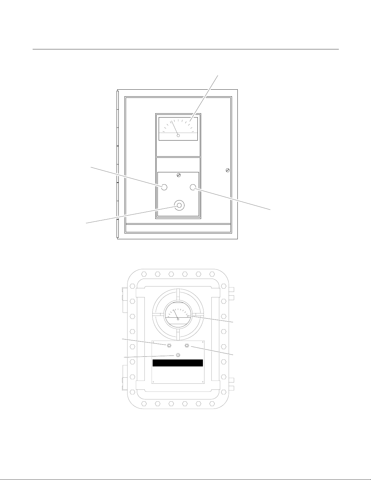
A. General Purpose Enclosure
ZERO Adjust
RANGE Switch
Rosemount Analytical
Meter
Model 755
Oxygen Analyzer
SPAN Adjust
B. Explosion-Proof Enclosure
ZERO Control
RANGE Switch
Controls have slotted shafts for
screwdriver adjustment from
outside the enclosure.
Rosemount Analytical
Model 755
Oxygen Anal yzer
Figure 1-1. Model 755 - Front View
Meter
SPAN Adjust
1-2 Description and Specifications Rosemount Analytical Inc. A Division of Emerson Process Management

Model 755
Instruction Manual
748183-K
April 2002
RANGE
OPTION
01 0 to 1% 0 to 2.5% 0 to 5% 0 to 10%
02 0 to 5% 0 to 10% 0 to 25% 0 to 50%
03 0 to 10% 0 to 25% 0 to 50% 0 to 100%
04 0 to 1% 0 to 2.5% 0 to 5% 0 to 25%
06 90 to 100% 80 to 100% 60 to 100% 50 to 100%
b. Standard Zero-Suppressed Range
Options
With any zero-suppressed range the 0%
oxygen point lies off-scale below the lower
range-limit. In a zero-suppressed range
option the four ranges have the same upper
range-limit, but different lower range-limits.
There is a standard zero-suppressed range
option, as shown in Table 1-2 (page 1-3).
c. Special Range Options
On factory special order, the analyzer may
be provided with a special range option
incorporating any desired combination of
zero-based and zero-suppressed ranges,
arranged in ascending order according to
span.
SUB-RANGE A SUB-RANGE B SUB-RANGE C OVERALL RANGE
Table 1-2. Range Options
1-4 ALARM OPTION
If equipped with the alarm option:
1. On the Control Board there are two
comparator amplifiers, one each for the
ALARM l and ALARM 2 functions. Each
amplifier has associated set-point and
dead-band adjustments, set-point is
adjustable from l% to l00% of fullscale.
The dead-band is adjustable from l% to
20% of fullscale.
2. Alarm relay assembly, containing two
single-pole double-throw relays, one for
each of the alarm contacts. These
relays may be used to drive external,
customer-supplied alarm and/or control
devices.
1-3 ISOLATED CURRENT OUTPUT OPTIONS
An isolated current output is obtainable by
installation of the optional Current Output Board,
either during factory assembly or subsequently
in the field. The maximum load resistance for
this board is 850 ohms.
Rosemount Analytical Inc. A Division of Emerson Process Management Description and Specifications 1-3
1-5 CASE MOUNTING OPTIONS
General Purpose Enclosure, see drawing
632349.
Explosion Proof Enclosure, see drawing
643127.
1-6 ELECTRICAL OPTIONS
The analyzer is supplied, as ordered, for
operation on either 120 VAC, 50/60 Hz, or
240 VAC, 50/60 Hz.
Instruction Manual
G
748183-K
April 2002
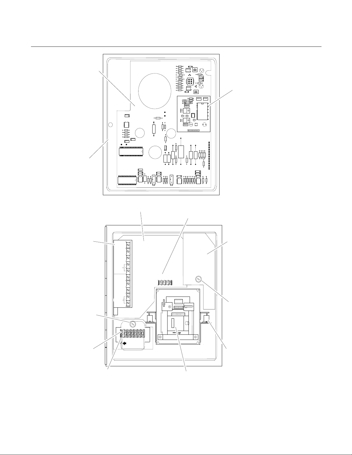
Control Board
Door
Model 755
Current Output
Board (Option)
R
R
R
1
U
I
Alarm Relay
Assembly
(Alarm Option)
Fuse
AC Power
AC Power
TB1
Transformer, Power
T1
(Behind TB1)
NO. 1
RESET
NO. 2
RESET
NO
COM
NC
NO
COM
NC
GND
Case Board
N
H
E
O
U
T
Recorder Output
TB2
Case Heater
Assembly
HOT
MA MV
+
-
+
COM
TB2
Fuse
Case
Heater
TB1
Detector/Magnet
Assembly Shock
Mount
Detector/Magnet
Assembly
General Purpose enclosure shown. Components mounted in same locations in Explosion-Proof enclosure.
Figure 1-2. Model 755 - Location of Major Components
1-4 Description and Specifications Rosemount Analytical Inc. A Division of Emerson Process Management

Model 755
1-7 SPECIFICATIONS
Instruction Manual
748183-K
April 2002
a. General
1
Catalog Number ............................ 191102 General Purpose for operation in non-hazardous locations
632440 Explosion-Proof for operation in hazardous locations
Standard Range Options
(% oxygen fullscale) 2.................... 0 to 1, 2.5, 5, and 10% fullscale
0 to 5, 10, 25, and 50% fullscale
0 to 10, 25, 50, and 100% fullscale
0 to 1, 2.5, 5 and 25% fullscale
0 to 1, 5, 10, and 25% fullscale
50 to 100, 60 to 100, 80 to 100, and 90 to 100% fullscale
Response Time (90% of fullscale) Factory set for 20 seconds; adjustable from 5 to 25 seconds.
Reproducibility............................... ±0.01% Oxygen or ±1% of fullscale, whichever is greater
Ambient Temperature Limits ......... Maximum: 49°C (120°F)
Minimum: -7°C (20°F)
Zero and Span Drift 3..................... ±1% of fullscale per 24 hours, provided that ambient temperature
does not change by more than 11.1°C (20°F).
±2.5% of fullscale per 24 hours with ambient temperature change
over entire range.
b. Sample
Dryness ......................................... Sample dewpoint below 43°C (110°F), sample free of entrained
liquids.
Temperature Limits ....................... Maximum: 66°C (150°F)
Minimum: 10°C (50°F)
Operating Pressure ....................... Maximum: 69 kPa (10 psig).
Minimum: 88.1 kPa absolute (660 mm Hg absolute pressure)
Flow Rate 4.................................... Maximum: 500 cc/min
Minimum: 50 cc/min
Recommended: 250 ±20 cc/min
Materials in Contact with
Sample Gas................................... 316 stainless steel, glass, titanium, Paliney No. 7, epoxy resin,
Viton-A, platinum, nickel.
1
Performance specifications based on recorder output.
2
For applications requiring suppressed ranges other than those provided, we recommend the Model 755A Oxygen Analyzer,
Catalog Number 617720. This instrument includes automatic correction for barometric pressure variations and provides
maximum accuracy for suppressed ranges. This particularly important at high level suppressed ranges such as 99 to 100%
where a barometric pressure change from standard 29.90 inches Hg (101 kPa) to 31.5 inches Hg (106 kPa) would result in
an actual oxygen change in the order of 5%. The Model 755A provides automatic barometric pressure correction and optimum accuracy for such suppressed ranges. The Model 755A also provides direct readout from 0.00% to 100.00% oxygen
on a digital display. Optimum resolution of the oxygen reading is provided.
3
Zero and span drift specifications based on following conditions: Operating pressure constant; ambient temperature change
from initial calibration temperature, less than 11.1 Celsius degrees (20 Fahrenheit degrees); deviation from set flow held to
within ±10% or ±20 cc/min, whichever is smaller.
4
Deviation from set flow would be held to within ±10% or ±20 cc/min, whichever is smaller. If so, zero and span drift will be
within specifications, provided that operating temperature remains constant.
Rosemount Analytical Inc. A Division of Emerson Process Management Description and Specifications 1-5

Instruction Manual
748183-K
April 2002
c. Electrical
Supply Voltage and Frequency
(selectable when ordered)............ Standard: 115 VAC ±10 VAC, 50/60 Hz
Power Consumption ...................... Maximum: 300 watts
Outputs.......................................... Standard: Field selectable voltage output of 0 to 10mV, 0 to
Alarm Option.................................. High-Low Alarm
Contact Ratings ..................... 5 amperes, 240V AC, resistive 3 amperes, 120 VAC inductive
Setpoint ......................................... Adjustable from 1% to 100% of fullscale
Deadband...................................... Adjustable from 1% to 20% of fullscale (Factory set at 10% of
d. Physical – General Purpose Enclosure
Mounting........................................ Standard: Panel mount
Enclosure Classification ................ Meets requirements for NEMA 3R
Refer to Installation Drawing 632349 in the rear of this manual.
Model 755
Optional: 230 VAC ±10 VAC, 50/60 Hz
100mV, 0 to 1V, or 0 to 5VDC
Optional: Isolated current output of 0 to 20mA or 4 to 20mA (with
Current Output Board)
1 amperes, 24V DC, resistive 5 amperes, 30 VDC resistive
5 amperes, 120V AC, resistive 3 amperes, 30 VDC inductive
fullscale)
Optional: Surface or stanchion mount accessory available
Air Purge Option1: NFPA 496 (1989) Type Z purge
e. Physical – Explosion-Proof Enclosure
Mounting........................................ Surface or wall
Enclosure Classification ................ Class I, Groups B, C, and D, Division 1 hazardous locations
(ANSI/NFPA 70)
Refer to Installation Drawing 643127 in the rear of this manual.
1
When installed with user supplied components, meets requirements for Class I, Division 2 locations per National Electrical
Code (ANSI/NFPA 70) for analyzers sampling nonflammable gases. Analyzers sampling flammable gases must be protected by a continuous dilution purge system in accordance with Standard ANSI/NFPA 496-1986, Chapter 8. Consult factory
for recommendations.
1-6 Description and Specifications Rosemount Analytical Inc. A Division of Emerson Process Management

Model 755
Instruction Manual
748183-K
April 2002
SECTION 2
INSTALLATION
2-1 UNPACKING
Carefully examine the shipping carton and
contents for signs of damage. Immediately
notify the shipping carrier if the carton or its
contents are damaged. Retain the carton and
packing materials until the instrument is
operational.
2-2 LOCATION
a. Location and Mounting
Shock and mechanical motion can reduce
instrument accuracy; therefore, mount the
instrument in an area that is as vibration
free as possible
General Purpose Enclosure
The analyzer is designed to meet NEMA
3R enclosure requirements and may be
mounted outdoors. Permissible ambient
temperature range is 20°F to 120°F (-7°C
to 49°C).
The analyzer is designed for either
surface or stanchion (optional kit)
mounting. Avoid mounting outside in
direct sunlight, or inside in a closed
building, where ambient temperature may
exceed the allowable maximum.
Explosion-Proof Enclosure
The analyzer can be either surface or wall
mounted and meets (ANSI/NFPA 70)
Class 1, Groups B, C, and D, Division 1
Hazardous Locations.
2-3 VOLTAGE REQUIREMENTS
DANGER
ELECTRICAL SHOCK HAZARD
For safety and proper performance this
instrument must be connected to a
properly grounded three-wire source of
power.
DANGER
ELECTRICAL SHOCK HAZARD
Do not operate without doors and covers
secure. Servicing requires access to live
parts which can cause death or serious
injury. Refer servicing to qualified
personnel.
CAUTION
ENCLOSURE INTEGRITY
With reference to Installation Drawing
632349 or 643127, any unused cable
conduit openings must be securely sealed
by permanent closures in order to provide
enclosure integrity in compliance with
personnel safety and environmental
protection requirements. The plastic
closures provided are for shipping
protection only.
NOTE
Refer to Installation Drawing 632349 or
643127 at the rear of this manual for
recommended cable conduit openings.
Rosemount Analytical Inc. A Division of Emerson Process Management Installation 2-1

Instruction Manual
748183-K
April 2002
Model 755
NOTE
For NEMA 3R service, all conduit must be
connected through approved fittings.
The analyzer is supplied, as ordered, for
operation on 120 VAC or 240 VAC, 50/60 Hz.
Make sure that the power source conforms to
the requirements of the individual instrument,
as noted on the name-rating plate.
2-4 ELECTRICAL CONNECTIONS
a. Line Power Connections
Electrical power is supplied to the
analyzer via a customer-supplied threeconductor cable, type SJT, minimum wire
size 18 AWG. Route power cable through
conduit and into appropriate opening in
the instrument case. Refer to Installation
Drawing (632349 or 643127). Connect
power leads to HOT, NEUT, and GND
terminals on TB1, Figure 2-1. Connect
analyzer to power source via an external
fuse or breaker, in accordance with local
codes.
NOTE
Cable connections and output selection
for potentiometric and current-actuated
devices are explained below.
NOTE
Do not allow internal cable service
loop to touch the shock-mounted
detector assembly or associated
sample inlet and outlet tubing. This
precaution ensures against possible
transmission of mechanical vibration
through the cable to the detector,
which could cause noisy readout.
Potentiometric Output
1. Insert RECORDER OUTPUT Selector
Plug (Figure 2-2, page 2-4) in position
appropriate to the desired output: 10
mV, 100 mV, 1 V, or 5 V.
2. On TB2 (Figure 2-1, page 2-3)
connect leads of shielded recorder
cable to MV+ and COM terminals.
3. Connect free end of output cable to
appropriate terminals of recorder or
other potentiometric device:
Do not draw power for associated
equipment from the analyzer power
cable.
b. Recorder Output Selection and Cable
Connections
If a recorder, controller, or other output
device is used, connect it to the analyzer
via a 22 or 24 AWG two-conductor
shielded cable. Route the cable through
conduit to the analyzer, and into the case
through the appropriate opening shown in
Installation Drawing (632349 or 643127).
Connect the shield only at the recorder
end.
NOTE
Route recorder cable through a
separate conduit, not with power cable
or alarm output cable.
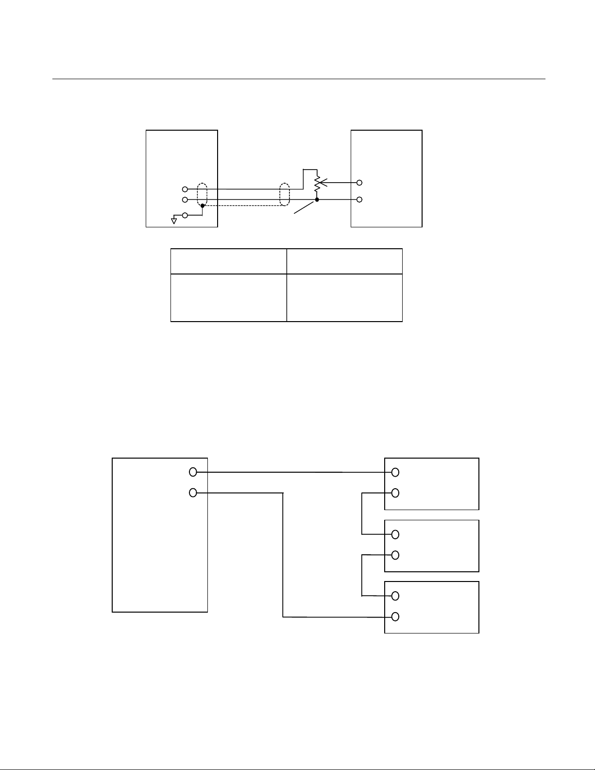
a. For device with a span of 0 to
10mV, 0 to 100mV, 0 to 1V, or 0 to
5V, connect cable directly to input
terminals of the device, making
sure polarity is correct.
b. For device with intermediate span,
i.e., between the specified values,
connect cable to device via a
suitable external voltage divider, as
shown in Figure 2-3, page 2-5.
Isolated Current Output (Option)
The isolated current output board (Figure
2-2, page 2-4) is optional, and can be
adjusted for either 0 to 20 mA or 4 to 20
mA. The adjustments made on this board
are for zero and span. To set output:
1. With analyzer meter at zero, adjust
R1 for desired zero level (typically 0
for 0 to 20 mA, 4 for 4 to 20 mA).
2-2 Installation Rosemount Analytical Inc. A Division of Emerson Process Management

Model 755
Instruction Manual
748183-K
April 2002
2. With analyzer at fullscale, adjust R2
for desired fullscale current (typically
20 mA).
3. To connect current activated output
devices:
4. On TB2 (Figure 2-1, page 2-3)
connect leads of shielded recorder
cable to MA+ and " - " terminals.
5. Connect free end of output cable to
input terminals of recorder or other
current-actuated device, making sure
that polarity is correct. If two or more
current-actuated devices are to be
used, they must be connected in
series, see Figure 2-4, page 2-5. Do
not exceed the maximum load
resistance (see Section 1-3, page 1-
3).
Explosion-Proof
Enclosure
6. For the set up of optional boards, the
isolated current output board
(optional) can be adjusted for either
0 to 20 mA or 4 to 20 mA. The
adjustments made on this board are
for zero and span.
a. With analyzer meter at zero, adjust
R1 for desired zero level, typically
0 for 0 to 20 mA, and 4 for 4 to 20
mA..
b. With analyzer meter at fullscale,
adjust R2 for desired fullscale
current (typically 20 mA).
7. Current and voltage outputs may be
utilized simultaneously, if desired.
Optional Alarm Kit
Power Connections
(see detail)
NO
NC
RESET
NO. 2
RESET
COM
NC
TB1
N
H
E
O
U
T
T
COM
-
TB2
Figure 2-1. Electrical Interconnection
General Purpose
Enclosure
+
mV Recorder
-
+
mA Recorder
-
120 VAC CONFIGURATION
Jumpers
N
GND
240 VAC CONFIGURATION
Jumper
GND
H
E
O
U
T
T
N
H
E
O
U
T
T
Rosemount Analytical Inc. A Division of Emerson Process Management Installation 2-3
Instruction Manual
748183-K
April 2002
Model 755
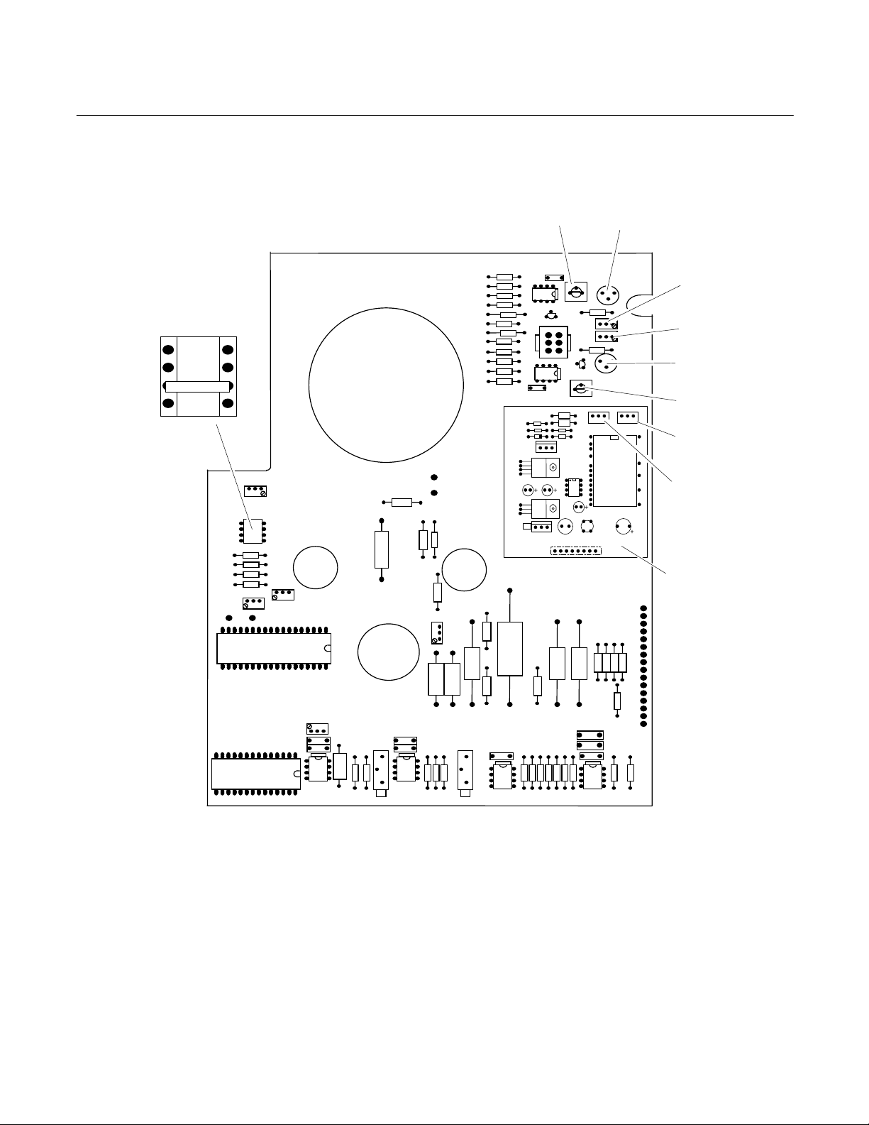
RECORDER OUTPUT
Selector Plug
5V
1V
100mV
10mV
R63
R64
R73
R78
R68
R3
I G O
U6
C4
R4
R2 R1
R5
R6
U3
U2
C2
U4
C3 CR1 C1
U1
J1
R8
R9
CR2
1
2
3
4
C5
I
G
O
I G O
R67
R1
R2
Current Output Board
Figure 2-2. Control Board – Adjustment Locations
2-4 Installation Rosemount Analytical Inc. A Division of Emerson Process Management
Model 755
Instruction Manual
748183-K
April 2002
755
Analyzer
Position of Recorder Output
Selector Plug
10 mV 1K Ohm
100 mV 10K Ohm
1 V 100K Ohm
5 V 2K Ohm
Voltage Divider
(Customer Supplied)
Minimum Permissible
Resistance for R1 + R2
Potentiometric
Recorder
Input
Terminals
(Make sure polarity
is correct)
Figure 2-3. Potentiometric Recorder with Non-Standard Span
+
Recorder
-
mA
+
-
755
Analyzer
+
Controller
-
+
Remote
Indicator
Figure 2-4. Model 755 Connected To Drive Current Output-Activated Output Devices
Rosemount Analytical Inc. A Division of Emerson Process Management Installation 2-5

Instruction Manual
748183-K
April 2002
Model 755
c. Output Connections, Initial Setup for
Dual Alarm Option
If so ordered the analyzer is factoryequipped with alarm output. Alternatively
the alarm feature is obtainable by
subsequent installation of the Alarm Kit.
Alarm Output Connections
The alarm output provides two sets of
relay contacts for actuation of alarm or
process-control functions. Leads from the
customer-supplied external alarm system
connect to terminals on the Alarm
Assembly, see Figure 2-1 page 2-3.
Note the following recommendations:
1. A fuse should be inserted into the line
between the customer-supplied power
supply and the alarm relay terminals
on the Alarm Relay Assembly.
2. If the alarm contacts are connected to
any device that produces radio
frequency interference (RFI), it should
be arc-suppressed. The 858728 Arc
Suppressor is recommended.
3. If at all possible, the analyzer should
operate on a different AC power
source, to avoid RFI.
Alarm Relay Characteristics
The Alarm 1 and Alarm 2 outputs of the
638245 Alarm Relay Assembly are
provided by two identical single-pole
double-throw relays. Relay contacts are
rated at:
5 amperes, 240 VAC resistive
1 ampere, 240 VAC inductive
5 amperes, 120 VAC resistive
3 amperes, 120 VAC inductive
5 amperes, 30 VDC resistive
3 amperes, 30 VDC inductive
Removal of AC power from the analyzer,
as in power failure, de-energizes both
relays, placing them in alarm condition.
Switching characteristics of the Alarm 1
and Alarm 2 relays are as follows:
Alarm 1 Relay
The Alarm I relay coil is de-energized
when the meter needle moves downscale
through the value that corresponds to
setpoint minus dead-band. This relay coil
is energized when the needle moves
upscale through the value that
corresponds to setpoint plus dead-band.
See Figure 2-5A, page 2-7.
Alarm 2 Relay
Relay The Alarm 2 relay coil is deenergized when the meter needle moves
upscale through the value that
corresponds to the setpoint plus deadband. This relay coil is energized when
needle moves downscale through the
value that corresponds to setpoint minus
dead-band, see Figure 2-5B, page 2-7.
Alarm Reset
Normally both the ALARM 1 and ALARM
2 functions incorporate automatic rest.
When the meter reading goes beyond the
selected limits, the corresponding relay is
de-energized; when the meter reading
returns within the acceptable range, the
relay is turned on.
The desired ALARM 1 or ALARM 2 alarm
function may be converted to manual
reset. The conversion consists of
substituting an external push-button or
other momentary-contact switch for the
jumper that normally connects the RESET
terminals on the Alarm Relay Assembly,
see Figure 2-1 page 2-3. If the
corresponding relay is now de-energized,
i.e., in alarm condition, the relay remains
de-energized until the operator
momentarily closes the switch.
2-6 Installation Rosemount Analytical Inc. A Division of Emerson Process Management
Model 755
Instruction Manual
748183-K
April 2002
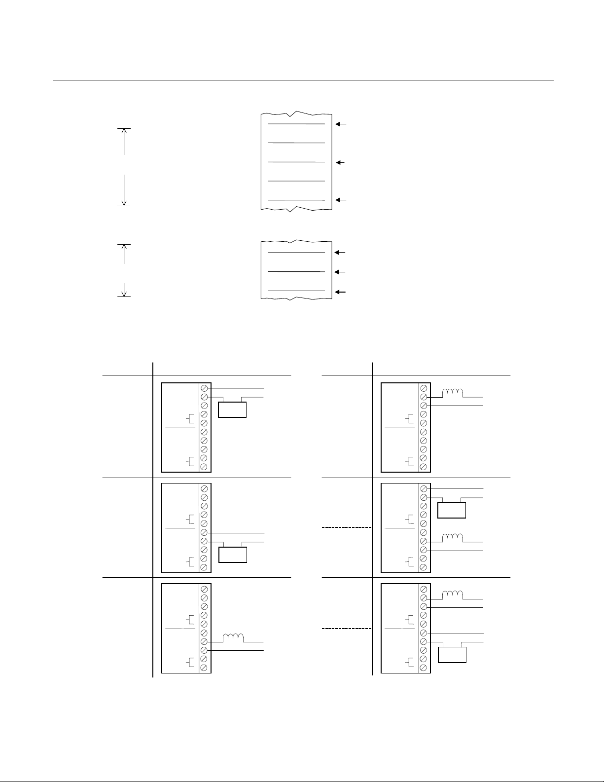
A. Typical ALARM 1 Setting
DEADBAND SET FOR
20% OF FULLSCALE
B. Typical ALARM 2 Setting
DEADBAND SET FOR
10% OF FULLSCALE
Low Alarm,
Fail-Safe
Percent of Fullscale
No. 1
COM
RESET
COM
RESET
No. 2
INPUT SIGNAL
Percent of Fullscale
INPUT SIGNAL
Figure 2-5. Typical Alarm Settings
NO
NC
NO
NC
Alarm Bell
or Lamp
40
30
20
55
50
45
115 VAC
When input signal moves upscale through this point, the coil of
ALARM 1 relay (K1) is energized, providing continuity between the
common and normally-closed contacts of the relay.
ALARM 1 Setpoint
When input signal moves downscale through this point, the coil of
ALARM 1 relay (K1) is de-energized, providing continuity between the
common and normally-open contacts of the relay.
When input signal moves upscale through this point, the coil of
ALARM 2 relay (K2) is de-energized, providing continuity between the
common and normally-open contacts of the relay.
ALARM 2 Setpoint
When input signal moves upscale through this point, the coil of ALARM
2 relay (K2) is energized, providing continuity between the common
and normally-closed contacts of the relay.
REQUIREMENT TYPICAL CONNECTIONSREQUIREMENT TYPICAL CONNECTIONS
Solenoid
No. 1
RESET
RESET
No. 2
NO
COM
NC
NO
COM
NC
N
H
Low Control
Limit,
Fail-Safe
Valve
115 VAC
H
N
High Alarm,
Fail-Safe
Low Control
Limit,
Fail-Safe
No. 1
RESET
RESET
No. 2
No. 1
RESET
RESET
No. 2
COM
COM
COM
COM
NO
NC
NO
NC
NO
NC
NO
NC
Alarm Bell
or Lamp
Solenoid
Valve
115 VAC
115 VAC
N
H
H
N
Lower
Low Alarm
Indicator,
Fail-Safe
Low Control,
Fail-Safe
High Control,
Fail-Safe
Higher
High Alarm
Indicator,
Fail-Safe
No. 1
RESET
RESET
No. 2
No. 1
RESET
RESET
No. 2
COM
COM
COM
COM
NO
NC
NO
NC
NO
NC
NO
NC
Alarm Bell
or Lamp
Solenoid
Valve
Solenoid
Valve
Alarm Bell
or Lamp
115 VAC
115 VAC
115 VAC
115 VAC
N
H
H
N
H
N
N
H
Figure 2-6. Relay Terminal Connections
Rosemount Analytical Inc. A Division of Emerson Process Management Installation 2-7

Instruction Manual
748183-K
April 2002
Model 755
Fail-Safe Applications
By appropriate connection to the doublethrow relay contacts, it is possible to
obtain either a contact closure or a
contact opening for an energized relay.
Also either a contact closure or a contact
opening may be obtained for a deenergized relay. It is important that for failsafe applications, the user understand
what circuit conditions are desired in
event of power failure and the resultant
relay de-energization. Relay contacts
should then be connected accordingly,
see Figure 2-6 page 2-7.
Alarm Setpoint Adjustment
The ALARM 1 and ALARM 2 circuits have
independent setpoint and dead-band
adjustments. Before the ALARM 1 and
ALARM 2 setpoints can be set, the alarm
dead-band must be calibrated according
to the following procedure.
1. Set the front panel TEST switch to
position 1.
2. Introduce upscale span gas through
analyzer at a flow rate of 50 to 500
cc/min.
3. Verify that ALARM 1 and ALARM 2
dead-band adjustments, R73 and R78
(Figure 2-2, page 2-4) are turned fully
counter-clockwise to set the deadband at minimum. Normally these
potentiometers are factory-set for
minimum dead-band. Both
potentiometers must remain at this
setting throughout calibration of the
alarm setpoint adjustments.
b. Adjust SPAN control to give a
display or recorder reading exactly
fullscale. If the fullscale setting
cannot be reached, set to a reading
higher than the desired alarm
setpoint.
c. Set ALARM 1 calibration
adjustment, R63, to its clockwise
limit (Figure 2-2, page 2-4). Rotate
R63 counter-clockwise the
minimum amount required to
energize ALARM 1, relay K1. Verify
that the alarm has been energized
with the ohmmeter on the relay
contacts (Figure 2-7, page 2-9).
6. Calibration of ALARM 2, LOW.
a. Rotate setpoint adjustment, R68,
fully counter-clockwise.
b. Adjust SPAN control for display or
recorder reading exactly fullscale. If
the fullscale setting cannot be
reached, then set to a reading
higher than the desired alarm
setpoint.
c. Set ALARM 2 calibration
adjustment, R67, to its clockwise
limit. Rotate R67 counterclockwise, the minimum amount
required to energize ALARM 2,
relay K2. Verify that the alarm has
been energized with the ohmmeter
on the relay contacts (Figure 2-7,
page 2-9).
7. Setpoint adjustment of ALARM 1,
HIGH.
4. Connect an ohmmeter to relay
terminals on 638254 Alarm Relay
Assembly to verify when alarms have
been energized.
5. Calibration of ALARM 1, HIGH.
a. Rotate setpoint adjustment, R64,
fully counter-clockwise.
2-8 Installation Rosemount Analytical Inc. A Division of Emerson Process Management
a. With span gas flowing, adjust SPAN
control to read desired alarm
setpoint on display or recorder.
b. Rotate setpoint adjustment, R64,
clockwise to energize relay.
c. Check this setting by adjusting the
SPAN control to lower the output
below the setpoint. This will deenergize the relay. Rotating R64
Model 755
Instruction Manual
748183-K
April 2002
above the setpoint will energize the
relay.
8. Setpoint adjustment of ALARM 2,
LOW.
a. With span gas flowing, adjust the
SPAN control to read desired alarm
setpoint on display or recorder.
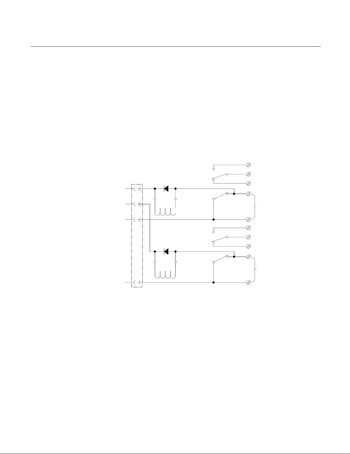
+15V
-15V
ALARM 1
ALARM 2
J5
1
14
2
4
-
14
6
-
CR1
CR2
K1
K2
13
13
b. Rotate setpoint adjustment, R68,
c. Check setting by adjusting the
1
5
12 8
1
5
12 8
clockwise to energize relay.
SPAN control to lower the output
below the setpoint. This will
energize the relay. Rotating R68
above the setpoint will de-energize
the relay.
NO
9
COM
NC
ALARM 1
RESET
NO
9
COM
NC
ALARM 2
RESET
2. RELAYS SHOWN IN ENERGIZED POSITION.
1. CR1 AND CR2 ARE ANY 600 V, 1 AMP DIODE.
NOTES:
Figure 2-7. Alarm Relay Option Schematic Diagram
Rosemount Analytical Inc. A Division of Emerson Process Management Installation 2-9

Instruction Manual
748183-K
April 2002
Model 755
2-5 CALIBRATION GASES
WARNING
HIGH PRESSURE GAS CYLINDERS
Calibration gas cylinders are under
pressure. Mishandling of gas cylinders
could result in death, injury, or property
damage. Handle and store cylinders with
extreme caution and in accordance with
manufacturer instructions. Refer to
General Precautions for Handling and
Storing High Pressure Gas Cylinders, page
P-4.
Analyzer calibration consists of establishing a
downscale calibration point and an upscale
calibration point.
Downscale calibration may be performed on a
range that will be used during sample
analysis. For maximum precision, however, it
should be performed on the range of highest
sensitivity, i.e., most narrow span.
Preferably upscale calibration should be
performed on a range to be used in sample
analysis. In some applications, however, it
may be desirable to perform upscale
calibration on a range of higher sensitivity,
i.e., more narrow span, and then move the %
RANGE switch to the desired operating range.
For example, if the operating range is to be 0
to 50% oxygen, upscale calibration may be
performed on the 0 to 25% range to permit
use of air as the upscale standard gas.
Recommendations on calibration gases for
various operating ranges are tabulated in
Table 2-1, page 2-10, and are explained in
Sections 2-5a (page 2-11) and 2-5b (page 2-
11).
Each standard gas should be supplied from a
cylinder equipped with dual-stage metaldiaphragm type pressure regulator, with
output pressure adjustable from 0 to 50 psig
(0 to 34.5 kPa).
A. ZERO BASED RANGES
RANGE % O
0 to 1 Nitrogen 0.9% O2, balance N2
0 to 2.5 Nitrogen 2.3% O2, balance N2
0 to 5 Nitrogen 4.5% O2, balance N2
0 to 10 Nitrogen 9% O2, balance N2
0 to 25 Nitrogen Air (20.93% O2)
0 to 50 Nitrogen 0.45% O2, balance N2
0 to 100 Nitrogen 100% O2
RANGE % O
90 to 100 91% 0.5% O2, balance N2 High-purity O2
80 to 100 82% 1% O2, balance N2 100% O2
60 to 100 62% 1% O2, balance N2 100% O2
50 to 100 52% 1% O2, balance N2 100% O2
Each standard gas used should have a composition within the specified limits, and should have a
certified analysis provided by the supplier.
2
2
RECOMMENDED DOWNSCALE
STANDARD GAS
B. ZERO SUPPRESSED RANGES
RECOMMENDED DOWNSCALE
STANDARD GAS
NOTE
Table 2-1. Calibration Range for Various Operating Ranges
RECOMMENDED UPSCALE
STANDARD GAS
RECOMMENDED UPSCALE
STANDARD GAS
2-10 Installation Rosemount Analytical Inc. A Division of Emerson Process Management
 Loading...