


R
OSEMOUNT ANALYTICAL
M
ODEL
XYGEN MONITOR
O
I
NSTRUCTION MANUAL
7003D
748054-K

OTICE
N
The information contained in this document is subject to change without notice.
Ryton® is a registered trademark of Phillips Petroleum Co.
Teflon® is a registered trademark of E.I. duPont de Nemours and Co., Inc.
Manual Part Number 748054-K
October 2000
Printed in USA
Rosemount Analytical Inc.
4125 East La Palma Avenue
Anaheim, California 92807-1802 US A

C
PREFACE
SAFETY SUMMARY ..........................................................................................P1
SPECIFICATIONS - PERFORMANCE...............................................................P4
SPECIFICATIONS - ELECTRICAL ....................................................................P4
SPECIFICATIONS - ALARM..............................................................................P5
SPECIFICATIONS - PHYSICAL.........................................................................P5
SPECIFICATIONS - SENSOR ...........................................................................P6
CUSTOMER SERVICE, TECHNICAL ASSISTANCE AND FIELD SERVICE............P7
RETURNING PARTS TO THE FACTORY.........................................................P7
TRAINING ......................................................................................................P7
DOCUMENTATION............................................................................................P7
ONTENTS
COMPLIANCES .................................................................................................P8
S
ECTION
1.1 OXYGEN MONITOR ...................................................................................1
1.2 SENSORS...................................................................................................2
S
ECTION
2.1 UNPACKING AND FACILITY PREPARATION ...........................................5
2.2 LOCATION AND MOUNTING.....................................................................5
2.3 ELECTRICAL CONNECTIONS...................................................................6
1. I
2. I
2.3.1 Line Power Connection..................................................................6
2.3.2 System Grounding Connection......................................................6
2.3.3 Sensor Cable Connection..............................................................7
2.3.4 Output Cable Connection...............................................................7
2.3.5 Output Connections for Alarms......................................................10
NTRODUCTION
NSTALLATION
748054-K Rosemount Analytical October 2000
Model 7003D Oxygen Monitor
i

ONTENTS
C
SECTION 2. (CONTINUED)
2.4 SENSORS - RECHARGEABLE.................................................................. 12
2.4.1 Installation of Sensor and Fast-Response Flow Kit....................... 12
2.4.2 Installation of Sensor and In-Line Flow Kit.................................... 14
2.4.3 Installation of Sensor and Submersion Kit .................................... 17
2.5 SENSORS - NON-RECHARGEABLE......................................................... 20
2.5.1 Conversion Of Oxygen Monitor From Use With Rechargeable
Sensor To Use With Non-Rechargeable Sensor.......... 20
2.5.2 Installation of Sensor and In-Line Flow Assembly......................... 20
2.5.3 Installation of Sensor with Submersion Assembly......................... 21
SECTION 3. STARTUP AND CALIBRATION
3.1 SYSTEM STARTUP ................................................................................... 25
3.2 CALIBRATION............................................................................................ 25
3.2.1 Calibration with Air ........................................................................ 26
3.2.2 Calibration with Span Gas............................................................. 26
3.3 SELECTION OF ALARM RANGE, SETPOINT, AND DEADBANDS.......... 26
3.4 CURRENT OUTPUT RANGE..................................................................... 29
SECTION 4. OPERATION
4.1 ROUTINE OPERATION.............................................................................. 31
4.2 RECOMMENDED CALIBRATION FREQUENCY....................................... 31
4.3 FREQUENCY OF SENSOR RECHARGING.............................................. 31
S
ECTION
5.1 ELECTROCHEMICAL THEORY................................................................. 33
5.2 VARIABLES INFLUENCING OXYGEN MEASUREMENT.......................... 34
5. T
HEORY
ii
October 2000 Rosemount Analytical 748054-KModel 7003D Oxygen Monitor

SECTION 6. ROUTINE SERVICE AND TROUBLESHOOTING
6.1 RECHARGEABLE SENSORS.....................................................................35
6.1.1 Recharging Sensor........................................................................36
6.1.2 Rejuvenating Cathode .................................................................38
6.1.3 Cell Separator Kit...........................................................................39
6.2 NON-RECHARGEABLE SENSORS ...........................................................39
6.3 TROUBLESHOOTING ................................................................................39
6.3.1 Checking Rechargeable Sensor and Cable...................................40
6.3.2 Checking Non-Rechargeable Sensor and Cable...........................42
ONTENTS
C
S
ECTION
7. R
EPLACEMENT PARTS
7.1 CIRCUIT BOARD REPLACEMENT POLICY ..............................................43
7.2 REPLACEMENT PARTS.............................................................................43
7.3 REPLACEMENT PARTS - SENSORS........................................................44
7.3.1 Rechargeable Sensors..................................................................44
7.3.2 Non-Rechargeable Sensors...........................................................45
748595 M
G
ENERAL PRECAUTIONS FOR HANDLING
W
ARRANTY
F
IELD SERVICE AND REPAIR FACILITIES
ATERIAL SAFETY DATA SHEET (ELECTROLYTE
& S
TORING HIGH PRESSURE CYLINDERS
)
748054-K Rosemount Analytical October 2000
Model 7003D Oxygen Monitor
iii

ONTENTS
C
FIGURES
1-1. Model 7003D Oxygen Monitor ................................................................... 1
1-2. Rechargeable Sensor................................................................................ 3
1-3. Non-Rechargeable Sensor........................................................................ 3
2-1. Power Supply Board.................................................................................. 7
2-2. Connections for Potentiometric Recorder with Non-Standard Span.......... 9
2-3. Typical Example of Oxygen Monitor Connected in Series with Several
Current Actuated Devices............................................................. 9
2-4. Rechargeable Sensor with Fast Response Flow Assembly....................... 13
2-5. Mounting Rechargeable Sensor in Fast Response Flow Assembly........... 13
2-6. Typical Installation Orientation of Rechargeable Sensor and Fast
Response Flow Assembly............................................................ 14
2-7 Rechargeable Sensor with Gland and In-Line Flow Assembly................... 16
2-8. Preferred Installation Orientation of Rechargeable Sensor and
In-Line Flow Assembly.................................................................. 16
2-9. Rechargeable Sensor with Submersion Assembly.................................... 18
2-10. Typical Installation of Rechargeable Sensor and Submersion
Assembly...................................................................................... 18
2-11. Typical Permanent Installation of Rechargeable Sensor with
Submersion Assembly During Plant Construction........................ 19
2-12. Typical Installation of Sensor/Submersion Assembly in an
Existing Plant................................................................................ 19
2-13. Dimensions and Components of Non-Rechargeable Sensor with
In-Line Flow Kit............................................................................. 22
2-14. Typical Installation of Non-Rechargeable Sensor with In-Line Flow Kit... 23
2-15. Dimensions and Components of Non-Rechargeable Sensor with
Submersion Kit............................................................................. 23
2-16. Typical Installation of Non-Rechargeable Sensor with Submersion Kit... 24
3-1. Display Board............................................................................................. 28
3-2. Isolated Current Output Board................................................................... 29
5-1. Rechargeable Oxygen Sensor - Sectional View........................................ 33
6-1. Rechargeable Sensor - Exploded View ..................................................... 36
T
ABLES
6-1. Rechargeable Sensor Troubleshooting Guide........................................... 41
6-2. Non-Rechargeable Sensor Troubleshooting Guide................................... 42
iv
October 2000 Rosemount Analytical 748054-KModel 7003D Oxygen Monitor

DRAWINGS (LOCATED IN REAR OF MANUAL)
620434 Schematic Diagram, Isolated V/I Board
622228 Interconnect Diagram, Model 7003D Oxygen Monitor
622530 Schematic Diagram, Display Board
622538 Schematic Diagram, Power Supply Board
622617 Outline and Mounting Drawing, Model 7003D Oxygen Monitor
ONTENTS
C
748054-K Rosemount Analytical October 2000
Model 7003D Oxygen Monitor
v

ONTENTS
C
NOTES
vi
October 2000 Rosemount Analytical 748054-KModel 7003D Oxygen Monitor

P
REFACE
SAFETY SUMMARY
To avoid explosion, loss of life, personal injury and damage to this equipment and on-site
property, all personnel authorized to install, operate and service the Model 7003D Oxygen
Monitor should be thoroughly familiar with and strictly follow the instructions in this manual.
Save these instructions.
If this equipment is used in a manner not specified in these instructions, protective
systems may be impaired.
DANGER is used to indicate the presence of a hazard which will cause severe
personal injury, death, or substantial property damage if the warning is ignored.
WARNING is used to indicate the presence of a hazard which can cause severe
personal injury, death, or substantial property damage if the warning is ignored.
CAUTION is used to indicate the presence of a hazard which will or can cause minor
personal injury or property damage if the warning is ignored.
NOTE is used to indicate installation, operation or maintenance information which is
important but not hazard-related.
WARNING: ELECTRICAL SHOCK HAZARD
Do not operate without doors and internal circuit panel secure. Servicing
requires access to live parts which can cause death or serious injury. Refer
servicing to qualified personnel.
For safety and proper performance this instrument must be connected to a
properly grounded three-wire source of power. Electrical installation must be
made in accordance with any applicable national or local codes.
Alarm switching relay contacts wired to separate power source must be
disconnected before servicing.
748054-K Rosemount Analytical October 2000
Model 7003D Oxygen Monitor
P1
REFACE
P
WARNING: PARTS INTEGRITY
Tampering or unauthorized substitution of components may adversely affect
safety of this product. Use only factory documented components for repair.
WARNING: HIGH PRESSURE GAS CYLINDERS
This analyzer requires periodic calibration with known zero and standard gases.
Refer to General Precautions for Handling and Storing High Pressure Cylinders,
at the rear of this manual.
WARNING: ENCLOSURE INTEGRITY
Unused cable conduit entries must be securely sealed by flameproof closures to
provide enclosure integrity in compliance with personnel safety and
environmental protection requirements. The plastic closures provided are for
shipping protection only. When installing instrument, observe all notes on
drawing 622617 (in rear of this manual).
WARNING: ELECTRICAL SHOCK HAZARD
To avoid shock hazard and AC pickup, do not route potentiometric output or
current output cables through the same conduit as power cable or alarm output
cable.
WARNING: CORROSIVE MATERIAL
Concentrated nitric acid is used in rejuvenating the sensor cathode (Section
6.1.2). This material is highly corrosive.
P2
October 2000 Rosemount Analytical 748054-KModel 7003D Oxygen Monitor

REFACE
P
CAUTION: CONDUIT GROUNDING
The non-metallic enclosure does not provide grounding between conduit
connections. Use grounding-type bushings and jumper wires.
748054-K Rosemount Analytical October 2000
Model 7003D Oxygen Monitor
P3

REFACE
P
SPECIFICATIONS - PERFORMANCE
OPERATING RANGE
0 - 19.99% to 0 to 25% oxygen by volume
S
AMPLE TEMPERATURE
32°F to 110°F (0°C to 44°C)
A
MBIENT TEMPERATURE
-20°F to 122°F (-29°C to 50°C) for in strument
A
MBIENT HUMIDITY
Up to 95% relative humidity, non-condensing
S
YSTEM LINEARITY
For constant sample temperature after correction for sensor zero offset:
±1% of fullscale
SPECIFICATIONS - ELECTRICAL
P
OWER REQUIREMENTS
107 to 127 VAC, 50/60 Hz, 0.2 A or 214 to 254 VAC, 50/60 Hz, 0.1
P
OTENTIOMETRIC OUTPUT
Selectable: 0-25%, 0-10%, 0-5% or 0-1% oxygen fullscale
Minimum load: 2K ohms
V
OLTAGE OUTPUT
Selectable: 0-10V, 0-5V, or 0-1V fullscale
C
URRENT OUTPUT (OPTION
Isolated 0-20mA or 4-20mA over same range as potentiometric output.
Minimum load: 600 ohms.
)
P4
October 2000 Rosemount Analytical 748054-KModel 7003D Oxygen Monitor

REFACE
P
S
PECIFICATIONS
R
ANGE
- A
LARM
Selectable: 0-25%, 0-10%, 0-5%, or 0-1% oxygen fullscale
C
ONTACTS
Two independently adjustable SPDT relay contact actuations
C
ONTACT RATING (RESISTIVE LOAD
)
Maximum switching voltage: 250 VAC, 30 VDC
Maximum switching current: 3A
D
EADBAND
Adjustable from less than 2% to 20% of range at any setpoint
R
EPEATABILITY
±0.1% of range
SPECIFICATIONS - PHYSICAL
M
OUNTING
Standard: Panel mount
Optional: Surface mount, pipe mount
D
IMENSIONS
10.4 x 8.9 x 8.3 inches (265 x 225 x 210 mm) HxWxD
W
EIGHT
4.2 lbs (1.9 kg)
E
NCLOSURE
NEMA-4X general purpose.
Optional air purge designed to NFPA-496 Type Z.
S
ENSOR CABLE
1
1000 ft (305 m) Maximum length between instrument and sensor.
1
The optional air purge, when installed along with user supplied components, is designed to equip the instrument
enclosure with Type Z purge protection per Standard ANSI/NFPA 496-1986. This reduces the classification within the
enclosure from Class I, Division 2 (normally non-hazardous) to non-hazardous, thus permitting installation in a location
classified Class I, Groups A, B, C, D, Division 2. This method of protection is recognized in Article 500-1 of the National
Electrical Code (NEC)< ANSI/NFPA 70.
748054-K Rosemount Analytical October 2000
Model 7003D Oxygen Monitor
P5

REFACE
P
SPECIFICATIONS - SENSOR
TYPE
Rechargeable, non-rechargeable (disposable)
STABILITY
±1% of fullscale at any given temperature per 24 hours, for an equilibrated
sensor
T
EMPERATURE COMPENSATIONS
32°F to 110°F (0°C to 44°C) ±6% of reading
60°F to 90°F (15°C to 32°C) ±3% of reading
For any other 30°F (16°C) ±4% of reading
R
ESPONSE TIME
90% in 20 seconds for a step change, using an equilibrated sensor at 25°C
S
AMPLE PRESSURE
0 to 50 psig (0 to 345 kPa)
P6
October 2000 Rosemount Analytical 748054-KModel 7003D Oxygen Monitor

REFACE
P
CUSTOMER SERVICE, TECHNICAL ASSISTANCE AND FIELD SERVICE
For order administration, replacement Parts, application assistance, on-site or factory
repair, service or maintenance contract information, contact:
Rosemount Analytical Inc.
Process Analytical Division
Customer Service Center
1-800-433-6076
RETURNING PARTS TO THE FACTORY
Before returning parts, contact the Customer Service Center and request a Returned
Materials Authorization (RMA) number. Please have the following information when
you call: Model Number, Serial Number, and Purchase Order Number or Sales Order
Number.
Prior authorization by the factory must be obtained before returned materials will be
accepted. Unauthorized returns will be returned to the sender, freight collect.
When returning any product or component that has been exposed to a toxic, corrosive
or other hazardous material or used in such a hazardous environment, the user must
attach an appropriate Material Safety Data Sheet (M.S.D.S.) or a written certification
that the material has been decontaminated, disinfected and/or detoxified.
Return to:
Rosemount Analytical Inc.
4125 East La Palma Avenue
Anaheim, California 92807-1802
USA
T
RAINING
A comprehensive Factory Training Program of operator and service classes is
available. For a copy of the Current Operator and Service Training Schedule contact
the Technical Services Department at:
Rosemount Analytical Inc.
Phone: 1-714-986-7600
FAX: 1-714-577-8006
D
OCUMENTATION
The following Model 7003D Oxygen Monitor instruction materials are available.
Contact Customer Service or the local representative to order.
748054 Instruction Manual (this document)
748054-K Rosemount Analytical October 2000
Model 7003D Oxygen Monitor
P7

REFACE
P
COMPLIANCES
The Model 7003D Oxygen Monitor is designed to comply with applicable American
standards for protection against electrical shock, mechanical and fire hazards in nonhazardous (ordinary) locations. The instrument must be installed in accordance with
the provisions of the National Electrical Code (NEC), ANSI/NFPA 70, and/or any
applicable national or local code(s), and operated and maintained in the
recommended manner.
The oxygen sensors and interconnecting cable used with the Model 7003D Oxygen
Monitor are non-incendive in normal operation and comply with the requirements of
Articles 501-3 (b)(1) c and 501-4 (b), Exception, of the National Electrical Code,
ANSI/NFPA 70-1987, for installations in Class I, Groups A, B, C, D Division 2
classified locations.
P8
October 2000 Rosemount Analytical 748054-KModel 7003D Oxygen Monitor
I
NTRODUCTION
1
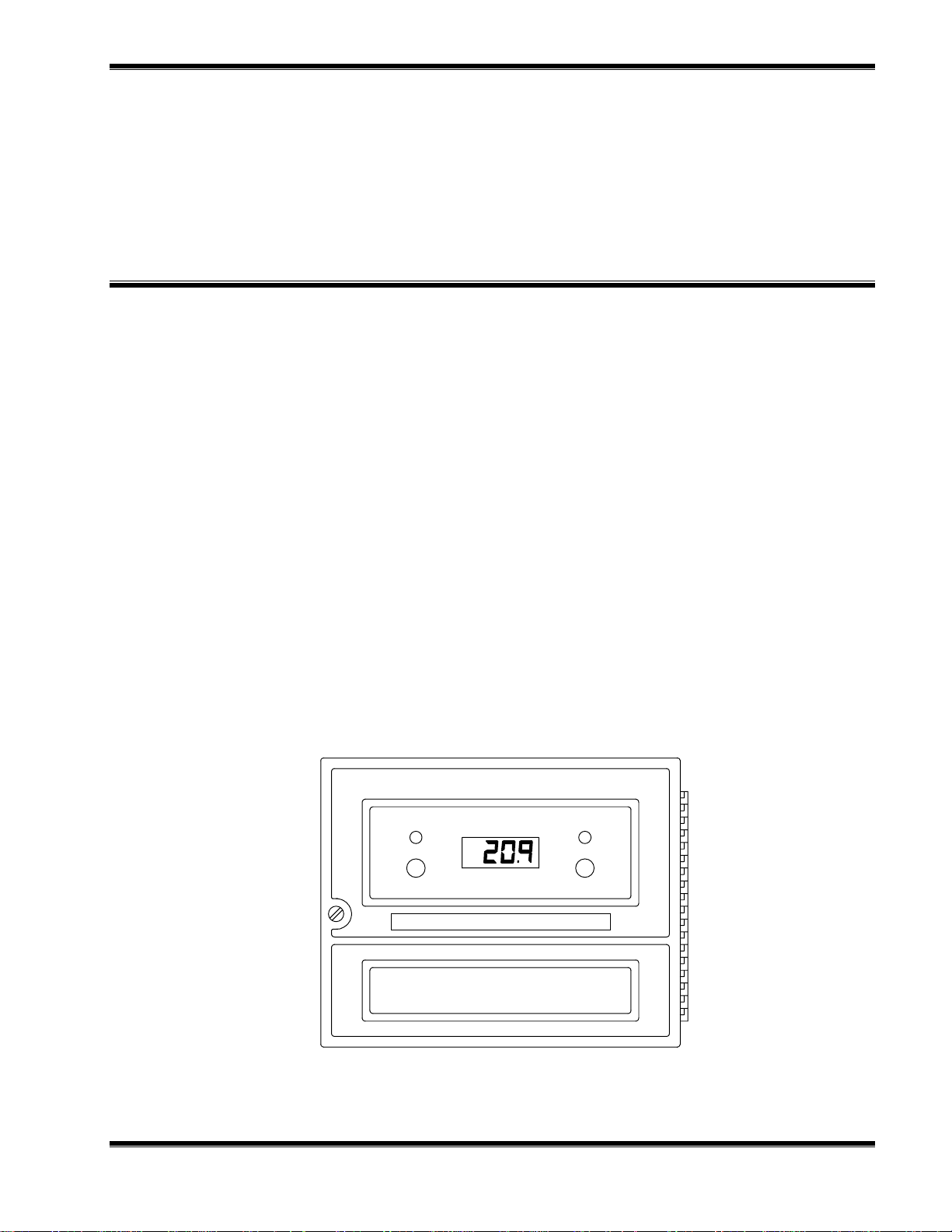
The Model 7003D Oxygen Monitor (Figure 1-1) automatically and continuously
measures the oxygen concentration in gaseous samples. The determination is based
on measurement of the electrical current developed by an amperometric sensor in
contact with the sample.
The monitor provides direct readout of concentration in % by volume. Alarms and a
potentiometric output are provided as standard. The fullscale range of the alarms and
the potentiometric output are each independently selectable. Thus, the range of the
potentiometric output may be changed without the need to readjust alarm setpoints.
The Model 7003D is used with a sensor which is housed in a submersion assembly or
flow assembly and is connected to the monitor by a multi-conductor shielded cable.
1.1 OXYGEN MONITOR
The oxygen monitor conditions the sensor output signal to provide direct readout of
oxygen in % by volume. It also contains current-measuring circuitry, operating
controls, digital display, alarms, and signal outputs provisions.
LOW
SET PT
Model 7003D Oxygen Monitor
IGURE
F
748054-K Rosemount Analytical October 2000
1-1. M
ODEL
7003D O
XYGEN MONITOR
LOW
%
SET PT
Model 7003D Oxygen Monitor
1

NTRODUCTION
I
The monitor is designed for panel mounting. Accessory Pipe Mounting Kit permits the
oxygen monitor to be mounted on a vertical or horizontal pipe. Accessory Wall
Mounting Kit permits wall (surface) mounting. An optional air purge kit is designed to
meet requirements for NFPA-496 Type Z air purge (see specifications) .
An accessory Isolated Current Output Board provides a field-selectable 0 to 20 mA, or
4 to 20 mA isolated current output.
1.2 SENSORS
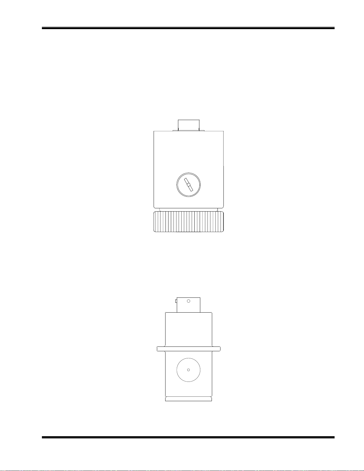
Rosemount Analytical offers rechargeable and disposable oxygen sensors which can
be used with the Model 7003D. See Figures 1-2 and 1-3. These sensors are supplied
alone or in kits: Submersion, in-line flow, and fast response.. Sensors are available
constructed of polypropylene or Ryton. See Sections 2.4 - Sensors, Rechargeable,
2.5 - Sensors - Non-Rechargeable and 7.3 - Sensors, Replacement Parts for
additional information.
ECHARGEABLE
R
The fast-response flow assembly allows minimum volume gas flow that permits
mounting the sensor in a flowing gas stream. Sample is supplied at slightly above
atmospheric pressure, flows through the assembly and discharges to atmospheric
pressure. Internal volume of the assembly is low to minimize system response time.
ECHARGEABLE
R
The in-line pressure compensated flow assembly permits mounting the sensor in a
variable pressure gas stream at pressures up to 50 psig (345 kPa). The typical
application is in-line monitoring with the flow assembly connected directly into the
process stream pipeline. An alternative application involves discharge to atmospheric
pressure where discharge rates are high.
ECHARGEABLE
R
The submersion assembly permits placing the sensor at depth, in an open or closed
vessel, at a maximum pressure of 50 psig (345 kPa). The submersion assembly
provides a convenient means of mounting the sensor, and also affords protection for
the sensor cable connection a feature particularly desirable in high humidity
environments.
AST-RESPONSE FLOW
- F
- IN-L
- S
INE FLOW
UBMERSION ASSEMBLY
NON-R
The in-line flow assembly permits mounting the sensor in a flowing gas stream. Also
included is a universal mounting bracket and a cable assembly for connecting the
disposable oxygen sensor to the monitor.
2
ECHARGEABLE
- IN-L
INE FLOW
October 2000 Rosemount Analytical 748054-KModel 7003D Oxygen Monitor
NTRODUCTION
I
NON-R
ECHARGEABLE
UBMERSION
- S
The submersion assembly adapts the oxygen sensor so that it may be inserted
through the wall of a vessel or pipe to monitor the oxygen concentration existing in the
vessel or pipe.
IGURE
F
IGURE
F
1-2. R
ECHARGEABLE SENSOR
1-3. NON-R
ECHARGEABLE SENSOR
748054-K Rosemount Analytical October 2000
Model 7003D Oxygen Monitor
3
 Loading...