

Rosemount Manual: 6081-C Wireless Contacting Conductivity Analyzer Abridged | Rosemount Manuals & Guides
Instruction Manual 6081-C
LIQ_MAN_ABR_6081-C February 2014
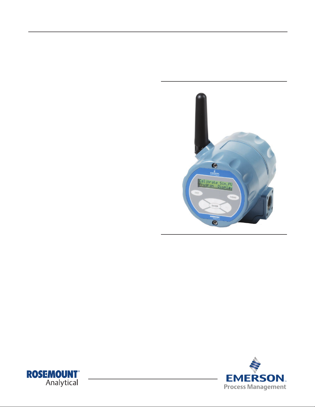
6081-C
Contacting Conductivity Transmitter
Figure 1. 6081-C
Essential Instructions – Read this before proceeding
Rosemount Analytical designs, manufactures, and tests its products to meet many national and international standards.
Because these instruments are sophisticated technical products, you must properly install, use, and maintain them to
ensure they continue to operate within their normal specications. The following instructions must be adhered to and
integrated into your safety program when installing, using, and maintaining Rosemount Analytical products. Failure
to follow the proper instructions may cause any one of the following situations to occur: Loss of life; personal injury;
property damage; damage to this instrument; and warranty invalidation.
• Read all instructions prior to installing, operating, and servicing the product. If this Instruction Manual is not the correct
manual, telephone 1-800-654-7768 and the requested manual will be provided. Save this Instruction Manual for future
reference.
• If you do not understand any of the instructions, contact your Rosemount representative for clarication.
• Follow all warnings, cautions, and instructions marked on and supplied with the product.
• Inform and educate your personnel in the proper installation, operation, and maintenance of the product.

6081-C Instruction Manual
February 2014 LIQ_MAN_ABR_6081-C
Essential Instructions (continued)
• Install your equipment as specied in the Installation Instructions of the appropriate Instruction Manual and per
applicable local and national codes. Connect all products to the proper electrical and pressure sources.
• To ensure proper performance, use qualied personnel to install, operate, update, program, and maintain the product.
• When replacement parts are required, ensure that qualied people use replacement parts specied by Rosemount.
Unauthorized parts and procedures can affect the product’s performance and place the safe operation of your process
at risk. Look alike substitutions may result in re, electrical hazards, or improper operation.
• Ensure that all equipment doors are closed and protective covers are in place, except when maintenance is being
performed by qualied persons, to prevent electrical shock and personal injury.
Note
The Rosemount 6081 and all other wireless devices should be installed only after the 1420 Wireless Gateway has been installed
and is functioning properly. Wireless devices should also be powered up in order of proximity from the 1420 Wireless Gateway,
beginning with the closest. This will result in a simpler and faster network installation.
Note
Shipping considerations for wireless products (Power Modules):
The unit was shipped to you without the power module installed. Please remove the power modules from the unit prior to
shipping.
Primary lithium power modules are regulated in transportation by the U. S. Department of Transportation, and are also covered
by IATA (International Air Transport Association), ICAO (International Civil Aviation Organization), and ARD (European Ground
Transportation of Dangerous Goods). It is the responsibility of the shipper to ensure compliance with these or any other local
requirements. Please consult current regulations and requirements before shipping.
The power module with the wireless unit contains two “C” size primary lithium/thionyl chloride power sources.
Each power module contains approximately 5 grams in each pack. Under normal conditions, the power module
materials are self-contained and are not reactive as long as the power modules and the pack integrity are maintained.
Care should be taken to prevent thermal, electrical or mechanical damage. Contacts should be protected to prevent
premature discharge.
Power module hazards remain when cells are discharged. Power modules should be stored in a clean and dry area. For
maximum power module life, storage temperature should not exceed 30 °C
WARNING
Use only with Rosemount Smart Power Module PN 701PBKKF or PN 00753-9220-0001
WARNING
Potential Electrostatic Hazard – The plastic antenna may present a potential electrostatic ignition hazard and must not be rubbed
or cleaned with a dry cloth.
WARNING
Mechanical Spark Hazard – The 6081 enclosure is made of aluminum alloy and given a protective polyurethane paint nish.
However, care should be taken to protect it from impact or abrasion if located in Zone 0.
This applies to any Intrinsically Safe installation, whether the Class, Division or Zone system is used.
2

Instruction Manual 6081-C
LIQ_MAN_ABR_6081-C February 2014
Quick Start Guide - 6081 Contacting Conductivity Transmitter
1. Install the Power Module inside the rear enclosure. Follow the installation instructions on p.9 “Power Module
Installation”.
2. Wire the sensor to the transmitter. Refer to the sensor instruction sheet for details.
3. Once the connections are secure and veried, install the Power Module to power to the transmitter.
4. When the transmitter is powered up for the rst time, Quick Start screens appear. Using Quick Start is easy.
a. A blinking eld shows the position of the cursor.
b. Use the ◄ or ► key to move the cursor left or right. Use the▲ or ▼ key to move the cursor up or down or to
increase or decrease the value of a digit. Use the ▲ or ▼ key to move the decimal point.
c. Press ENTER to store a setting. Press EXIT to leave without storing changes. Pressing EXIT also returns the display
to the previous screen.
5. Choose a local language.
6. Choose measurement: Sensor type: 2-Electrode, 4-Electrode.
7. Select measurement: conductivity, resistivity, TDS, salinity or one of the % concentration choices.
8. Enter cell constant: for the sensor. Refer to the tag attached to the sensor.
9. Select wireless update rate. Select ENTER to choose the default update rate of 60 seconds or enter a value from 1
second to 3,600 seconds (60 minutes).
10. Choose temperature units: °C or °F
11. Choose Yes to Setup the Wireless Network or No if the Network ID and the Join Key have already been entered.
12. Enter the 5-digit Wireless Network ID. This ID number must match the Network ID of the 1420 Wireless Gateway.
13. Enter the 8-digit Network Join Key number 1 of 4 to match the 1420 Wireless Gateway. See the Note below for
clarication.
14. Enter the 2nd, 3rd, and 4th set of Network Join Key numbers, to match the Model 1420 Wireless Gateway.
15. The transmitter will exit Quick Start and display the live measurement screen.
16. To change the Network ID or Join Key, HART address, or measurement-related settings from the default values, and to
set security codes, press MENU. Select Program and follow the prompts. Refer to the appropriate menu tree.
17. To return the transmitter to default settings, choose Reset Analyzer in the Program menu.
Note regarding Wireless Device Configuration
In order to communicate with the 1420 Wireless Gateway, and ultimately the Information System, the transmitter must
be congured to communicate with the wireless network. This step is the wireless equivalent of connecting wires from a
transmitter to the information system. Using a Field Communicator or AMS, or the local keypad on the device, enter the
Network ID and Join Key so that they match the Network ID and Join Key of the gateway and other devices in the network.
The Network Join Key consists of four (4) blocks, each with an eight digit code. The code of each block must match
its corresponding block in the 1420 in order for the 6081 to join the network. If the Network ID and Join Key are not
identical, the transmitter will not communicate with the network. The Network ID and Join Key may be obtained from the
1420 Wireless Gateway on the Setup>Network>Settings page on the web server. The nal device network conguration
piece is the Update Rate. This is 60 seconds by default. This may be changed at commissioning, or at any time via AMS
or the 1420 Wireless Gateway’s web server. The Update Rate should be between 1 second and 3,600 seconds. When
device conguration is completed, remove the power module and replace the rear cover of the transmitter until the time
of actual live installation in the process. Properly tighten the screws and install plugs or cable gland ttings in the conduit
openings to prevent the entry of moisture during storage.
Note
For installation and operation at high elevations, slight convex bulging of the front keypad overlay is possible. If bulging occurs, it
is recommended to unscrew the two Philips head screws that faster the front cover to the central housing to release any internal
pressure. This will equalize the device’s internal pressure to the ambient atmospheric pressure. Re-tighten the two Philips head
screws to secure the front cover before device installation or operation. Make sure to perform the pressure equalization in a clean,
dry area.
3

6081-C Instruction Manual
February 2014 LIQ_MAN_ABR_6081-C
Figure 2. Menu Tree for 6081 Contacting Conductivity Wireless Transmitter
4

Instruction Manual 6081-C
LIQ_MAN_ABR_6081-C February 2014
Product Description
When used with appropriate sensors, the 6081-C can measure conductivity, resistivity, total dissolved solids or custom curve variables
in the range of 0–600 mS/cm of a liquid and transmit data wirelessly with a radio transceiver which uses HART 7 communication
protocol. The instrument has a local operator interface consisting of a keyboard and LCD display which can be used to observe process
parameters or to congure the 6081. This instrument is available with approvals for use in hazardous areas.
General Specifications
Enclosure: Cast aluminum. NEMA 4X. IP66
Dimensions: 6.55” x 5.40” x 5.15” (166mm x 137mm x 131mm).
Conduit Openings: 3/4” FNPT
Ambient Temperature: -4 to 149 °F (-20 to 65 °C)
Storage Temperature: -22 to 158 °F (-30 to 70 °C)
Relative Humidity: 0 to 95% (non-condensing)
Weight/Shipping Weight: 7 lbs/8 lbs (3.2/3.6 kg)
Digital Communications: HART 7 Wireless HART
TM
Wireless Specifications
Output: Wireless HART V7
Transmit Rate: User selectable, 1/sec. to 1/60 min (via Smart Wireless Gateway or AMS™)
Measurement update rate: 1/sec. to 1/60 min
Antenna: PBT/PC integrated omni-directional antenna
Radio Frequency: 2.4 GHz DSSS
Transmission distance - line of sight: about 600 ft (ideal RF conditions and power module condition)
Power: Lithium thionyl chloride long life power module
Power Module Life (estimated): Four years at once per minute update rate, 25 °C ambient, and minimum display usage.
Functional Specifications
Measurements: conductivity in the range 0 to 600,000 μS/cm (600mS/cm). Measurement choices are conductivity,
resistivity, total dissolved solids, salinity, and %concentration. The % concentration selection includes the choice of ve common
solutions (0–12% NaOH, 0–15% HCl, 0–20% NaCl, and 0–25% or 96–99.7% H2SO4).
Input filter: time constant 1–999 sec, default 2 sec.
Response time: 3 seconds to 100% of nal reading
Salinity: uses Practical Salinity Scale
Information and Status: Information screens display cell constant, zero offset in air, zero offset in water, RTD offset, faults and
warnings, ambient temperature, radio transmission status, network ID number, Power Module voltage and estimated life,
transmitter model, and software version.
The conductivity concentration algorithms for these solutions are fully temperature compensated. Three temperature
compensation options are available: manual slope (X%/°C), high purity water (dilute sodium chloride), and cation conductivity (dilute
hydrochloric acid). Temperature compensation can be disabled, allowing the analyzer to display raw conductivity.
Note
Selected 4-electrode, high range contacting conductivity sensors are compatible with 6081-C.
Display: 2-line, 16 character display supports display of μS/cm, mS/cm, MΩ-cm, % concentration, and ppm units. Display shows
temperature.
Recommended Sensors:
140 Retractable Conductivity
141 Insertion High Conductivity
142 Insertion Low Conductivity
150 Insertion/Submersion Conductivity
400/VP Screw-In Low Conductivity
401 Screw-In High Conductivity
402/VP Retractable Conductivity
403/VP Sanitary Conductivity
404 Low Flow Conductivity
410/VP Four Electrode Sensor
5
 Loading...