

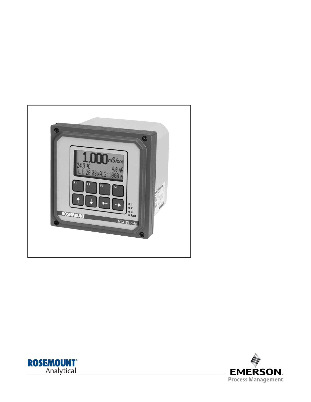
Model 54eC
Conductivity/Resistivity HART
®
Analyzer/Controller
Instruction Manual
51-54eC/rev.F
May 2006
ESSENTIAL INSTRUCTIONS
READ THIS PAGE BEFORE PRO-
CEEDING!
Rosemount Analytical designs, manufactures, and tests its
products to meet many national and international standards. Because these instruments are sophisticated technical products, you must properly install, use, and maintain
them to ensure they continue to operate within their normal
specifications. The following instructions must be adhered
to and integrated into your safety program when installing,
using, and maintaining Rosemount Analytical products.
Failure to follow the proper instructions may cause any one
of the following situations to occur: Loss of life; personal
injury; property damage; damage to this instrument; and
warranty invalidation.
• Read all instructions prior to installing, operating, and
servicing the product. If this Instruction Manual is not the
correct manual, telephone 1-800-654-7768 and the
requested manual will be provided. Save this Instruction
Manual for future reference.
• If you do not understand any of the instructions, contact
your Rosemount representative for clarification.
• Follow all warnings, cautions, and instructions marked
on and supplied with the product.
• Inform and educate your personnel in the proper installation, operation, and maintenance of the product.
• Install your equipment as specified in the Installation
Instructions of the appropriate Instruction Manual and
per applicable local and national codes. Connect all
products to the proper electrical and pressure sources.
• To ensure proper performance, use qualified personnel
to install, operate, update, program, and maintain the
product.
• When replacement parts are required, ensure that qualified people use replacement parts specified by
Rosemount. Unauthorized parts and procedures can
affect the product’s performance and place the safe
operation of your process at risk. Look alike substitutions may result in fire, electrical hazards, or improper
operation.
• Ensure that all equipment doors are closed and protective covers are in place, except when maintenance is
being performed by qualified persons, to prevent electrical shock and personal injury.
WARNING
ELECTRICAL SHOCK HAZARD
Making cable connections to and servicing this
instrument require access to shock hazard level
voltages which can cause death or serious injury,
therefore, disconnect all hazardous voltage
before accessing the electronics.
Relay contacts made to separate power sources
must be disconnected before servicing.
Electrical installation must be in accordance
with the National Electrical Code (ANSI/NFPA-
70) and/or any other applicable national or local
codes.
Unused cable conduit entries must be securely
sealed by non-flammable closures to provide
enclosure integrity in compliance with personal
safety and environmental protection requirements. Use NEMA 4X or IP65 conduit plugs supplied with the instrument to maintain the ingress
protection rating (IP65).
For safety and proper performance this instrument must be connected to a properly grounded
three-wire power source.
Proper relay use and configuration is the
responsibility of the user. No external connection to the instrument of more than 60VDC or
43V peak allowed with the exception of power
and relay terminals. Any violation will impair the
safety protection provided.
Do not operate this instrument without front
cover secured. Refer installation, operation and
servicing to qualified personnel.
WARNING
This product is not intended for use
in the residential, commercial or
light industrial environment per
certification to EN50081-2.
Emerson Process Management
Liquid Division
2400 Barranca Parkway
Irvine, CA 92606 USA
Tel: (949) 757-8500
Fax: (949) 474-7250
http://www.raihome.com
© Rosemount Analytical Inc. 2006

About This Document
This manual contains instructions for installation and operation of the Model 54eC
Conductivity/Resitivity HART Analyzer/Controller.
The following list provides notes concerning all revisions of this document.
Rev. Level
Date Notes
0 9/99 This is the initial release of the product manual. The manual
has been reformatted to reflect the Emerson documentation
style and updated to reflect any changes in the product offering.
0 11/01 Added trim output info
A 12/01 Revised spec and temp slope info
B 6/02 updated drawings on page 8
C 2/03 Removed Figure 3-2 (sensor wiring photo)
D 4/03 Updated CE info
E 4/05 Added note re ordering circuit board stack on page 63.
F 5/06 Noted 0-20 mA limitation for HART versions on pp. 21, 26, & 32.

MODEL 54eC TABLE OF CONTENTS
MODEL 54eC
MICROPROCESSOR ANALYZER
TABLE OF CONTENTS
Section Title Page
1.0 DESCRIPTION AND SPECIFICATIONS ................................................................ 1
1.1 General Description................................................................................................. 1
1.2 Description of Controls ............................................................................................ 1
1.3 Specifications........................................................................................................... 2
1.4 Ordering Information................................................................................................ 4
2.0 INSTALLATION....................................................................................................... 5
2.1 Locating the Controller ............................................................................................ 5
2.2 Unpacking and Inspection ....................................................................................... 5
2.3 Mechanical Installation ............................................................................................ 5
3.0 WIRING ................................................................................................................... 7
3.1 General.................................................................................................................... 7
3.2 Power Input Wiring .................................................................................................. 7
3.3 Analog Output Wiring .............................................................................................. 7
3.4 Alarm Relay Output Wiring...................................................................................... 7
3.5 Sensor Wiring.......................................................................................................... 9
3.6 Final Electrical Check.............................................................................................. 9
4.0 CALIBRATION ........................................................................................................ 11
4.1 Initial SetUp ............................................................................................................. 12
4.2 Entering the Cell Constant ...................................................................................... 13
4.3 Zeroing the Controller.............................................................................................. 14
4.4 Selecting the Temperature Compensation Type ..................................................... 15
4.5 Temperature Calibration .......................................................................................... 16
4.6 Calibrating the Sensor............................................................................................. 17
4.7 Temperature Compensation Options....................................................................... 18
4.8 Hold Mode ............................................................................................................... 19
4.9 Output Trim.............................................................................................................. 19
5.0 SOFTWARE CONFIGURATION ............................................................................. 20
5.1 Changing Output Setpoints (PID only) .................................................................... 24
5.2 Changing Alarm Setpoints....................................................................................... 25
5.3 Changing Output Setpoints (Normal) ...................................................................... 26
5.4 Testing Outputs and Alarms .................................................................................... 27
5.5 Choosing Display Options ....................................................................................... 29
5.6 Changing Output Parameters.................................................................................. 31
5.7 Changing Alarm Parameters ................................................................................... 34
6.0 THEORY OF OPERATION ..................................................................................... 40
6.1 Conductivity ............................................................................................................. 40
6.2 Temperature Correction........................................................................................... 40
6.3 Interval Timer........................................................................................................... 41
6.4 Alarm Relays ........................................................................................................... 42
6.5 Time Proportional Control (TPC) Mode................................................................... 42
6.6 Normal Mode........................................................................................................... 43
6.7 Analog Outputs........................................................................................................ 43
6.8 Controller Mode Priority........................................................................................... 44
6.9 PID Control.............................................................................................................. 45
i

MODEL 54eC TABLE OF CONTENTS
TABLE OF CONTENTS (Continued)
Section Title Page
7.0 SPECIAL PROCEDURES AND FEATURES ......................................................... 49
7.1 Password Protection................................................................................................ 49
7.2 Configuring Security ................................................................................................ 50
7.3 Temperature Slope Procedure (Linear Compensation) ........................................... 51
7.4 Determining Unknown Temperature Slopes (Linear Compensation)...................... 52
7.5 Changing the Reference Temperature..................................................................... 53
7.6 Special Substance Calibration................................................................................. 54
8.0 TROUBLESHOOTING ........................................................................................... 55
8.1 Displaying Diagnostic Parameters........................................................................... 58
8.2 Troubleshooting Guidelines..................................................................................... 59
8.3 Replacement Parts .................................................................................................. 63
9.0 RETURN OF MATERIALS ..................................................................................... 64
LIST OF FIGURES
Figure No. Title Page
1-1 Main Display Screen............................................................................. 1
2-1 Wall Mounting....................................................................................... 5
2-2 Pipe Mounting....................................................................................... 6
2-3 Panel Mounting..................................................................................... 6
3-1 Power Input and Relay Output Wiring for Model 54eC......................... 8
3-2 Sensor Wiring Diagram ........................................................................ 10
5-1 Outline of Menu Levels......................................................................... 23
5-2 Interval Timer Examples....................................................................... 38
6-1 Time Proportional Control..................................................................... 42
6-2 The Process Reaction Curve................................................................ 47
LIST OF TABLES
Table No. Title Page
4-1 Typical Temperature Slopes ................................................................. 15
5-1 Conductivity Settings List ..................................................................... 20
6-1 Controller Mode Priority Chart .............................................................. 44
8-1 Diagnostic Messages ........................................................................... 56
8-2 Quick Troubleshooting Guide ............................................................... 57
8-3 Troubleshooting Guide ......................................................................... 60
ii

1
MODEL 54eC SECTION 1.0
DESCRIPTION AND SPECIFICATIONS
SECTION 1.0
DESCRIPTION AND SPECIFICATIONS
1.1 GENERAL DESCRIPTION
The Model 54eC conductivity controller is a device
used to measure conductivity in chemical processes.
Conductivity is a function of ion concentration, ionic
charge, and ion mobility. Ions in water conduct current
when an electrical potential is applied across electrodes immersed in the solution. A controller system
consists of a microprocessor-based controller, a conductivity probe, and mounting hardware.
The controller can use an electrodeless toroidal probe
or a contacting probe with metal electrodes. Electrodeless (also called inductive) conductivity measurement
is especially useful for solutions containing abrasive
solids, highly conductive, or highly corrosive materials.
The contacting probe is used where conductivity is
below 200 micromhos, such as water rinses in metal
finishing or ultrapure boiler water applications. It uses
an electrode design for greater sensitivity because
these water solutions tend to be non-fouling.
All adjustments to the current outputs, alarm relays,
and calibration of the pH and temperature inputs can
be made using the controller's membrane keypad.
1.2 DESCRIPTION OF CONTROLS
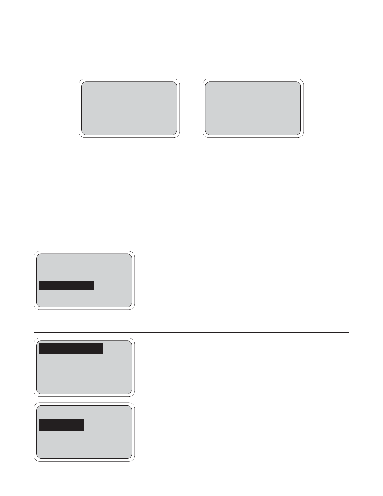
Figure 1-1 shows a diagram of the main display
screen. Similar diagrams are used throughout this
manual. The primary variable is continuously displayed in large numerals. The process temperature
and primary current output value are always displayed
on the second line of the main display screen. The
third line can be configured to read several different
items, as desired. In this case, it is displaying setpoints for alarms 1 and 2.
The F1-F4 keys are multifunction. The active operation
for that key is displayed as a label just above each
function key as needed. For example, F1 is usually
labeled Exit and F4 may be labeled Edit, Save, or
Enter. Pressing Enter 4 will access sub-menus, while
pressing Edit allows changing values and Save stores
the values in memory. Esc 3 can be used to abort
unwanted changes. Exit 1 returns to the previous
screen. Other labels may appear for more specialized
tasks.
The up t and down b keys are used to:
1. Move the cursor (shown in reverse video) up and
down on the menu screens.
2. Scroll through the list of options available for the
field shown in reverse video. When the last item
of a menu has been reached, the cursor will
rest on the third line of the display. If the cursor
is on the second line, there are more items to
see with the down arrow key.
3. Scroll through values when a highlighted numerical
value is to be set or changed.
The right and left keys are used to move the cursor to
the next digit of a number.
Green LEDs (labeled 1, 2, and 3) indicate when alarm
relays 1, 2, and 3 are energized. The fourth relay
indicates a fault condition. When a fault occurs, the
red LED (labeled FAIL) lights up, a descriptive error
message is displayed, and the action of the outputs
and relays will be as described in Section 5.6 and
Section 5.7 under fault value (e.g. 22 mA).
The red LED also indicates when the interval timer routine is activated and when the time limit has been
reached on a feed limit timer. For more information on
these subjects, see Section 5.7.
FIGURE 1-1. Main Display Screen
500
µS/cm
26.2°C. 12.0 mA
AL1: 2000μS AL2: 500μS

MODEL 54eC SECTION 1.0
DESCRIPTION AND SPECIFICATIONS
1.3 SPECIFICATIONS
PHYSICAL SPECIFICATIONS - GENERAL
Enclosure: Epoxy-painted cast aluminum
NEMA 4X (IP65),144 X 144 X 132mm, DIN size
(5.7 X 5.7 X 5.2 in.)
Front Panel: Membrane keyboard with tactile feed
back and user selectable security. Light gray, blue
and white overlay. Light gray enclosure, dark gray
bezel.
Display: Back-lit dot matrix LCD (7.0 x 3.5 cm), blue
on gray-green. The display contrast is compensated for ambient temperature.
Process Variable Character Height: 16mm (0.6 inch)
Electrical Classification:
Class I, Division 2, Groups A, B, C, & D.
T5 Ta=50°C. Dust ignition proof: Class II,
Division 1, Groups E, F, & G; Class III.
CSA-LR34186:
Max. relay contact rating: 28 Vdc; 110 Vac;
230 Vac; 6 amps resistive
FM: Max. relay contact rating: 28 Vdc resistive
150 mA - Groups A & B;
400 mA - Group C;
540 mA - Group D
Power:
Code -01: 100 - 127 VAC, 50/60 Hz ± 6%, 6.0 W;
200 - 253 VAC, 50/60 Hz ± 6%, 6.0 W
Code -02: 20 - 30 VDC, 6.0 W
Current Outputs:
Output 1: Process, Raw conductivity, or
Temperature
Output 2: Process, Raw conductivity, or
Temperature
Each output is galvanically isolated, 0-20 mA or 420 mA into 500 ohms maximum load at 115/230
Vac or 24 Vdc (Code -02) or 500 ohms maximum
load at 100/200 Vac. Output 1 includes digital signal 4-20 mA superimposed HART (Code -09 only).
EMI/RFI :EN61326
LVD (Code -01 only) : EN61010-1
Ambient Temperature:
0 to 50°C (32 to 122°F)
NOTE: The analyzer is operable from
-20 to 60°C (-4 to
140°F) with some degradation in display performance.
Relative Humidity: 95%, non-condensing
Alarms:
Relay 1 - Process, Temperature, or Interval Timer
Relay 2 - Process, Temperature, or Interval Timer
Relay 3 - Process, Temperature, or Interval Timer
Relay 4 - Fault alarm
Each relay has a dedicated LED on the front panel.
Relay Contacts: Relays 1-3: Epoxy sealed form A
contacts, SPST, normally open.
Relay 4: Epoxy sealed form C, SPDT.
Resistive Inductive
28 Vdc 5.0 Amps 3.0 Amps
115 Vac 5.0 Amps 3.0 Amps
230 Vac 5.0 Amps 1.5 Amps
Weight/Shipping Weight: 1.1 kg/1.6 kg (2.5 lb/3.5 lb)
2
MODEL 54eC SECTION 1.0
DESCRIPTION AND SPECIFICATIONS
3
INSTRUMENT SPECIFICATIONS @ 25°C
Measurement Range: –15 to 200°C (5 to 392°F)
Contacting: 0-20,000 µS/cm
Toroidal: 0-2 S/cm
Accuracy of Analyzer: (Analyzer connected to simulated sensor input)
Contacting Sensors: ±0.5% of reading, ± .005 µS/cm
Inductive Sensors: ±1% of reading, 200 µS/cm to 2 S/cm, ± 5 µS/cm
Repeatability: ±0.25% of reading
Stability: ±0.25% of output range/month, noncumulative
Ambient Temperature Coefficient: ± 0.01% of reading/°C
Temperature Compensation: -15 to 200°C (5 to 392°F) (automatic or manual)
Temperature Correction: High purity water (dilute sodium chloride), cation conductivity (dilute hydrochloric
acid), linear temperature coefficient (0.0 to 5.00%/°C), or none. High purity water and cation conductivity
temperature correction apply between 0 and 100°C. Linear temperature coefficient can be applied between
-5 and 200°C (23 to 392°F).
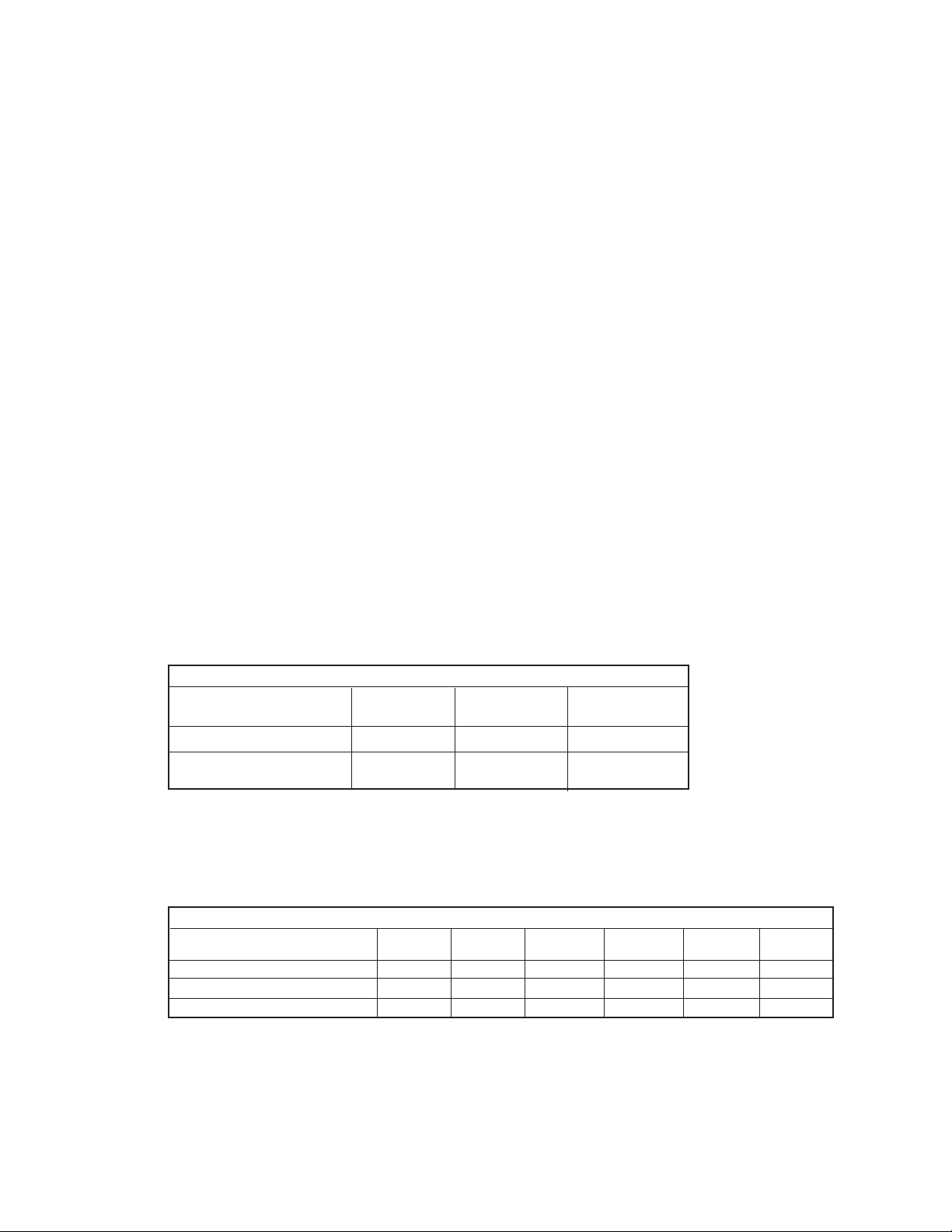
CONTACTING SENSORS
Conductivity Sensor 142, 400 142, 400 140, 141
Model Number 402, 403, 404 402, 403, 404 400, 402, 403
Cell Constant (/cm) 0.01 0.1 1.0
Recommended Conductivity 0-25 1-2000 10-10,000**
Range* (μS/cm)
INDUCTIVE SENSORS
Conductivity Sensor
Model Number 226 228 225 222 (1in.) 222 (2 in.) 242
Nominal Cell Constant 1.0 3.0 3.0 6.0 4.0 *
Minimum Conductivity (μS/cm) 50 200 200 500 500 100*
Maximum Conductivity (μS/cm) 1,000,000 2,000,000 2,000,000 2,000,000 2,000,000 1,500,000*
* Model 242 values depend on sensor configuration and wiring.
* For sensor linearity equal to or better than 1% with ENDURANCE series.
** ENDURANCE sensors with cell constant of 1.0/cm may be used for conductivity up to
20,000 μS/cm with linearity equal to or better than 2%.
SENSOR CHOICE GUIDELINES
The Model 54eC is compatible with both contacting and inductive conductivity sensors. The best sensor for an
application depends on many factors, among them are the conductivity to be measured, the compatibility of the
sensor's wetted materials with the process chemicals and conditions, and the mounting arrangement. The tables
below are provided as an aid for choosing an appropriate sensor.

MODEL 54eC SECTION 1.0
DESCRIPTION AND SPECIFICATIONS
4
1.4 ORDERING INFORMATION
The Model 54eC Conductivity Microprocessor Analyzer is housed in a rugged, NEMA 4X (IP65) epoxy-
painted cast aluminum enclosure and is compatible with both contacting and inductive conductivity sensors.
Standard features include a back-lit dot-matrix liquid crystal display, sensor diagnostics, dual isolated outputs,
and four relays. The analyzer can measure conductivity, resistivity, or percent (%) concentration as configured by
the user.
CODE OPTIONS
01 115/230 VAC, 50/60 Hz Power
02 24 VDC, 50/60 Hz Power
MODEL
54eC MICROPROCESSOR ANALYZER
CODE OPTIONS
09 HART Communications Protocol
20 Controller Outputs - PID and TPC
ACCESSORIES
PART NO. DESCRIPTION
2002577 Wall and two inch pipe mounting kit
23545-00 Panel mounting kit
23554-00 Cable glands, kit (Qty 5 of PG 13.5)
9240048-00 Stainless steel tag (specify marking)
54eC -01 -20 EXAMPLE
5
MODEL 54eC SECTION 2.0
INSTALLATION
SECTION 2.0
INSTALLATION
This section is for installation of the controller.
WARNING
All electrical installation must conform to the
National Electrical Code, all state and local
codes, and all plant codes and standards for
electrical equipment. All electrical installations
must be supervised by a qualified and responsible plant electrician.
2.1 LOCATING THE CONTROLLER
Position the Model 54eC controller to minimize the effects of temperature extremes and to avoid vibration
and shock. Locate the controller away from your
chemical process to protect it from moisture and
fumes.
Select an installation site that is more than 2 ft from
high voltage conduit, has easy access for operating
personnel, and is not exposed to direct sunlight.
2.2 UNPACKING AND INSPECTION
Inspect the exterior of the shipping container for any
damage. Open the container and inspect the controller
and related hardware for missing or damaged parts.
If there is evidence of damage, notify the carrier immediately. If parts are missing, contact Rosemount
Analytical customer support.
2.3 MECHANICAL INSTALLATION
2.3.1 Mounting the Controller
The Model 54eC controller may be supplied with a
mounting bracket accessory. If you use the mounting
bracket on wall or pipe installations, avoid mounting
on pipes which vibrate or are close to the process.
The bracket may be modified to mount the controller
on I-beams or other rigid members. You can also fabricate your own bracket or panel mount the controller
using the bracket as an example.
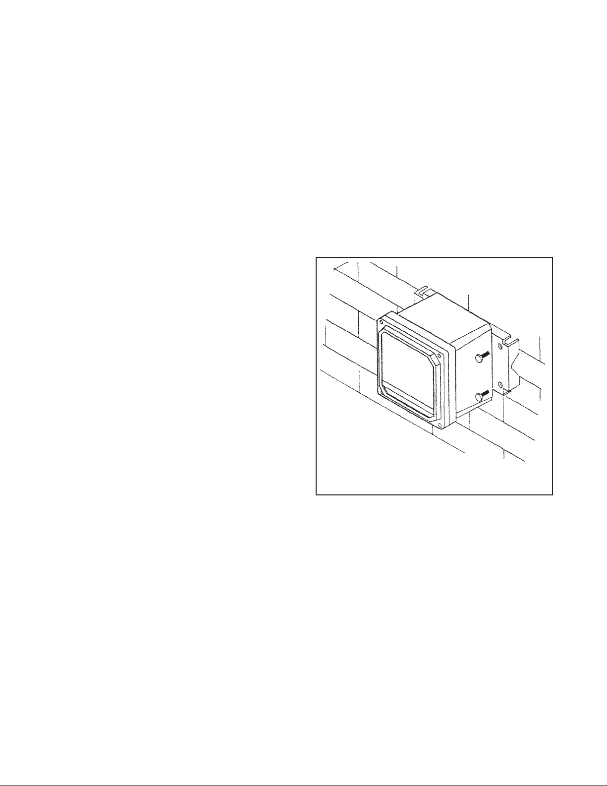
2.3.2 Wall or Surface Mounting:
1. Mount the bracket to the controller using the supplied four screws as shown in Figure 2-2.
2. Mount controller mounting bracket to wall using
any appropriate fastener such as screws, bolts,
etc (see Figure 2-1 below).
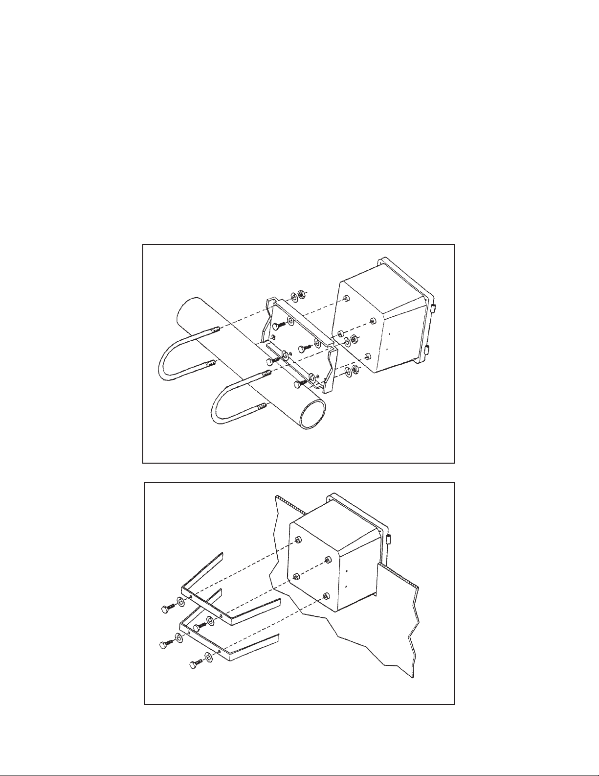
2.3.3 Pipe Mounting:
1. Attach the mounting bracket to the rear of the controller and tighten the four screws as shown in
Figure 2-2.
2. Place supplied U bolts around the mounting pipe
and through the pipe mounting bracket and
mounting bracket. Tighten the U bolt nuts until the
controller is securely mounted to the pipe.
FIGURE 2-1. Wall Mounting
6
FIGURE 2-2. Pipe Mounting
MODEL 54eC SECTION 2.0
INSTALLATION
FIGURE 2-3. Panel Mounting
2.3.4 Panel Mounting:
The controller is designed to fit into a 5.43 x 5.43 inch (DIN standard 137.9 x 137.9 mm) panel cutout (Figure
2-3). Installation requires both front and rear access.
1. Install the controller as shown in Figure 2-3. Insert the instrument enclosure through the front of the panel
cutout and align the panel mounting brackets as shown.
2. Insert two mounting bracket screws through each of the two mounting brackets and into the tapped holes in
the rear of the controller enclosure and tighten each screw.
3. Insert four panel mounting screws through each hole in the mounting brackets. Tighten each screw until the
mounting bracket holds controller firmly in place. To avoid damaging the controller mounting brackets, do not
use excessive force.

MODEL 54eC SECTION 3.0
WIRING
SECTION 3.0
WIRING
3.1 GENERAL
WARNING
All electrical installation must conform to the
National Electrical Code, all state and local
codes, and all plant codes and standards for
electrical equipment. All electrical installations must be supervised by a qualified and
responsible plant electrician.
NOTE
Wire only the analog and alarm outputs
required for your application. Be sure to read
the warning at the beginning of Section 2.0.
The Model 54eC has five access holes in the bottom of
the instrument housing which accept ½-in. strain relief
connectors or conduit fittings. Be sure to seal any
unused access holes. As you face the front of the unit,
the rear openings are for input power, and alarm relay
signals. The opening on the front left is for sensor
wiring only (DC). The front right is for analog output
wiring.
NOTE
For best EMI/RFI protection, the output
cable should be shielded and enclosed in an
earth grounded, rigid, metal conduit.
Connect the output cable's outer shield to
the earth ground connection on TB2 (Figure
3-1).
3.2 POWER INPUT WIRING
Figure 3-1 depicts the wiring detail for the Model 54eC.
Code -01: connect AC power to TB3, terminals 1 and
2 for 115 VAC (terminals 2 and 3 for 230 VAC). Code
-02: connect DC power to TB3 terminals 1, 2, and 3.
Connect earth ground to the nearby ground lug. A
good earth ground is essential for proper operation of
the controller. Be sure to provide a means of disconnecting the main power to the controller.
CAUTION
Do not apply power to the controller until all
electrical connections are made.
WARNING
Electrical connections to this equipment
must be made in accordance with the current National and Local Electrical Codes
in effect for the installation location.
3.3 ANALOG OUTPUT WIRING
The analog output wiring consists of two 4-20 mA signals: output one from terminals 4 and 5, output 2
from 1 and 2 on TB2, as shown in Figure 3-1. These
signals can be used for chart recorder, computer
monitoring, or PID control output. The analog outputs
can be programmed for 4-20 mA or for 0-20 mA,
direct or reverse acting. Current output 1 includes
superimposed HART (code -09 only).
3.4 ALARM RELAY OUTPUT WIRING
The controller has 3 "dry" alarm relay contacts which
are normally open. Alarm 1 is across terminals 4 and 5
on TB3. This alarm is typically used to control the pump
in a chemical feed system. Alarm 2 across terminals 6
and 7 on TB3 is usually used to operate a light or horn
as a means of alerting the chemical process operator
when conductivity/resistivity/%concentration is outside
the control range. Alarm 3 is across terminals 8 and 9
on TB3. All 3 of these alarms may be activated on conductivity/resistivity/%concentration or temperature.
They can also be used to control other pumps or valves
provided they are programmed to do so. Refer to
Section 5.0 to set up these functions.
All three alarm contacts on the Model 54eC are rated
for a maximum of 3 A, 115 VAC (1.5A, 230 VAC). If
your associated pump or valve exceeds this, use a
separate contact or relay rated for the external
device.
To use a contact output to control a pump, valve, or
light, the contact must be wired into a circuit together with a source of power for the device to be controlled. The power can be jumpered from the main
power into the controller and the circuit can be wired
as shown on the wiring diagrams, Figure 3-1.
7

8
MODEL 54eC SECTION 3.0
WIRING
FIGURE 3-1. Power Input and Relay Output Wiring for Model 54eC
NOTE: Maximum inductive load is 3.0 A at 115 V, 1.5 A at 230V. External power must be brought to relay contact. HART
communications superimposed on Output 1.
DWG. NO. REV.
4054EC03 C

9
MODEL 54eC SECTION 3.0
WIRING
3.5 SENSOR WIRING
Be sure that the conductivity sensor has been properly installed and mounted. Wire the sensor to the junction box
(if so equipped) and/or Model 54eC according to Figure 3-2, or use the wiring diagram drawing included inside the
controller.
The wiring diagrams show connections between the Model 54eC and the junction box used where distance
from the sensor to the controller exceeds the integral sensor cable length and interconnecting wire is
required. The interconnecting sensor wire recommended for contacting sensors is PN 9200275. Use of this
cable provides EMI/RFI protection and complete sensor diagnostics (for sensors so equipped). The maximum interconnecting wire length is 180 ft. For toroidal sensors, please see sensor manual for recommended interconnecting cable.
IMPORTANT
All interconnecting sensor cable ends must be properly dressed to prevent the individual sensor
and shield wires from shorting. All shields must be kept electrically separate all the way back to
the terminals on the Model 54eC. Check that there is no continuity between the shield wires and
any other sensor conductors or shields prior to connecting the sensor wiring to the terminals on
the Model 54eC. FAILING TO FOLLOW THESE INSTRUCTIONS WILL RESULT IN CONTROLLER
MALFUNCTION.
3.6 FINAL ELECTRICAL CHECK
CAUTION
To prevent unwanted chemical feed into the process and to prevent injury to operating personnel, disconnect the chemical feed pump and other external devices until the controller
is checked out, programmed, and calibrated.
When all wiring is completed, apply power to the controller. Observe the controller for any questionable behavior
and remove power if you see a problem. With the sensor in the process, the display will show a conductivity
although it may not be accurate.

MODEL 54eC SECTION 3.0
WIRING
10
FIGURE 3-2. Sensor Wiring Diagram

11
MODEL 54eC SECTION 4.0
CALIBRATION
SECTION 4.0
CALIBRATION
The following procedures are described in this section:
• Initial Setup (Section 4.1)
• Entering the cell constant (Section 4.2)
• Zeroing the controller (Section 4.3)
• Entering the temperature slope (Section 4.4)
• Standardizing temperature (Section 4.5)
• Standardizing conductivity (Section 4.6)
• Manual Temperature Compensation (Section 4.7)
• Hold Mode (Section 4.8)
NOTE
First Time Users should perform ALL of the
procedures in Sections 4.1 to 4.6.
INTRODUCTION
Calibration is the process of adjusting or standardizing the controller to a lab test (such as free acid titration) or a calibrated laboratory instrument, or standardizing to some known reference (such as a commercial chemical standard). Calibration ensures that
the controller reads an accurate, and therefore,
repeatable reading of conductivity and temperature.
This section contains procedures for the first time
use and for routine calibration of the Model 54eC
controller.
Since conductivity measurements are affected by
temperature, the Model 54eC reads the temperature
at the probe and compensates for the changing temperature by referencing all conductivity measurements to 25°C (77°F).
To ensure the controller's accuracy, it is important to
perform all the calibration procedures provided in this
section if you are:
• installing this unit for the first time
• changing or replacing a probe
• troubleshooting
After the initial calibration, the accuracy of the conductivity reading should be checked periodically against
some known standard of conductivity and temperature. This is described here and in Section 6.0,
Operating Procedures.
WARNINGS
Before performing any of these procedures, be sure to disable or disconnect the chemical feed
pumps or other external devices. (see placing controller in hold mode, Section 4.8)
Perform the calibration procedures in this section only in the order they are given. For an introduction to the controller keypad functions, see Section 1.0, Description and Specifications.
Do not attempt to calibrate the controller if the fault LED is lit or the display is showing fault messages. If either of these conditions exist, refer to Section 8.0, Troubleshooting.
12
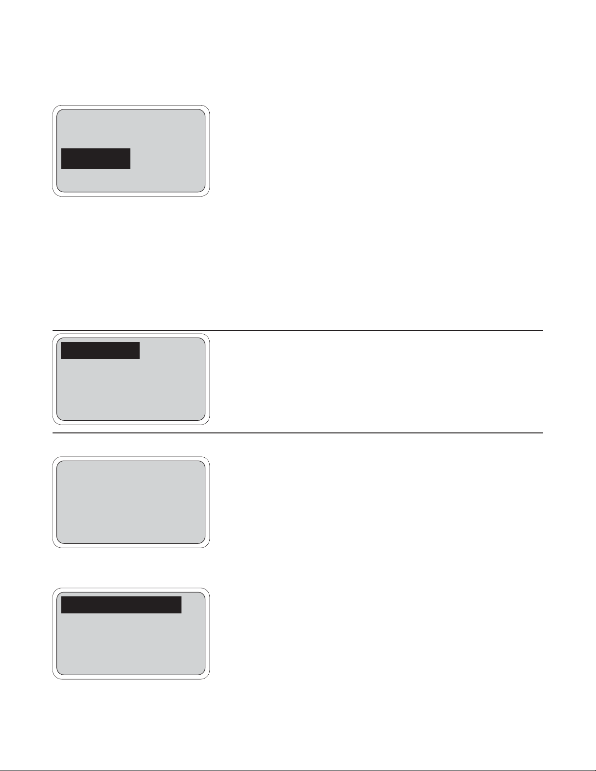
4.1 INITIAL SETUP
MODEL 54eC SECTION 4.0
CALIBRATION
1000
µS/cm
Hold mode: Off
Exit Cont Edit
500
µS/cm
26.2°C. 12.0 mA
AL1: 2000μS AL2: 500μS
NOTE
The controller has been configured at the factory for a toroidal
sensor ("inductive" mode). If the contacting conductivity probe is
used instead, go to Section 5.5 and change the Display Type to
"Contacting", BEFORE continuing with Initial Setup here.
The initial setup procedure should be used when first commissioning the
controller and when changing the conductivity probe. Some menu headers may appear that are not discussed here, but are included in Section
7.0 as advanced features of the controller that most new users will not
need. Initial setup should be conducted with the conductivity probe wired
to the controller with full length of extension cable (if any) for best results.
1. From the main display, press any key to obtain the main menu. With
the cursor on "Calibrate", press Enter 4.
NOTE
The hold mode screen (top left) will appear if the hold mode was
enabled in Section 5.6. Activate hold mode by pressing Edit 4,
using the arrow key to change Off to On, and then pressing Save
4. The hold mode holds the outputs and relays in a fixed state
to avoid process upsets to a control system. To leave the hold
mode in it's current state, press Cont 3.
2. The display will appear as on the left. Press the down arrow key 3
times to obtain the screen below and press Enter 4 to access the
menu for initial setup.
Note that the menu item shown in reverse video is at the bottom of
the display. This is the visual cue that you have reached the last
menu selection at this level.
Continue the initial setup procedure in Section 4.2
3. To return to the Main Display, keep pressing Exit until the main display appears.
Calibrate sensor
Adjust temperature
Temp compensation
Exit Enter
Temp compensation
Initial setup
Output Trim
Exit Enter
MAIN DISPLAY
Calibrate
Diagnostic variables
Program
Exit Enter
MAIN MENU
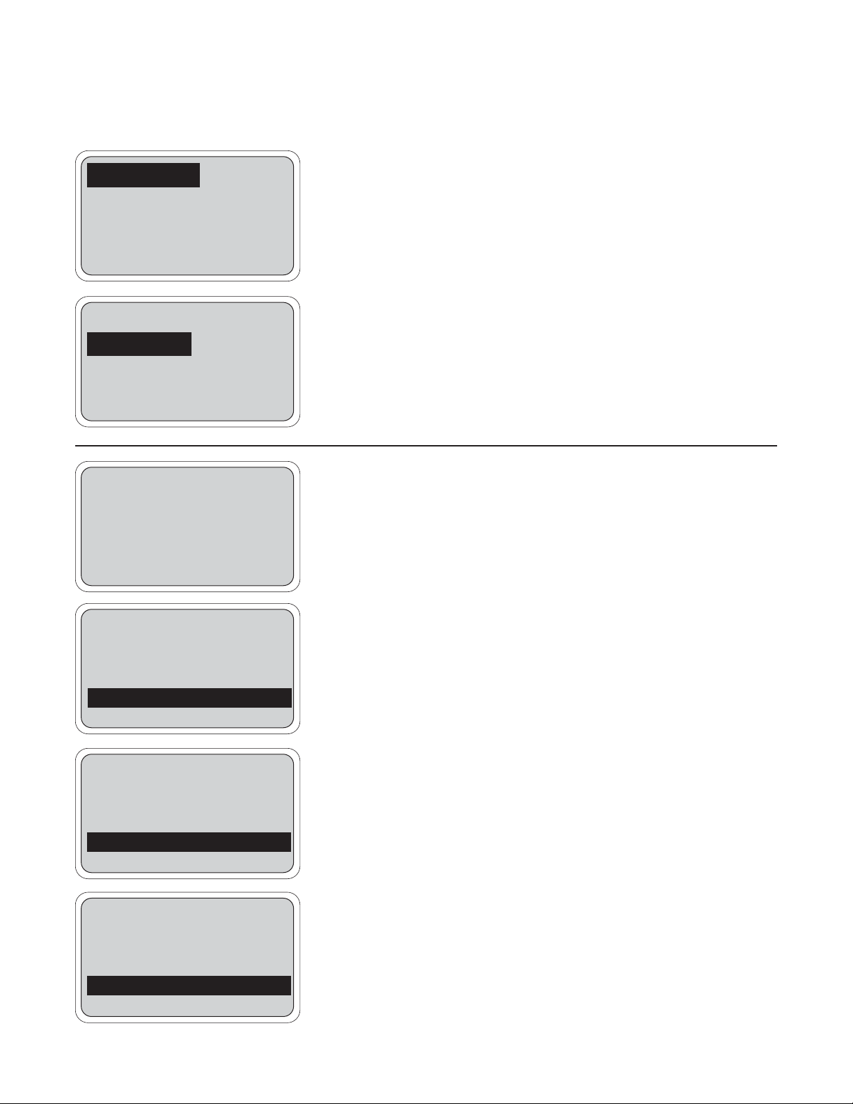
4.2 ENTERING THE CELL CONSTANT
MODEL 54eC SECTION 4.0
CALIBRATION
Adjust temperature
Temp compensation
Initial setup
Exit Enter
The cell constant should be entered:
• When the unit is installed for the first time
• When the probe is replaced
• During troubleshooting
This procedure sets up the controller for the probe type connected to the
controller. Each type of probe has a specific cell constant:
• Small toroidal (Model 228 or 225) = 3.0
• Large toroidal (Model 226) = 1.0
• Flow-through toroidal (Model 222): 1-inch = 6.0; 2-inch = 4.0
• Low conductivity (contacting sensors) = 0.01 to 10.0
All cell constants can be located on the cable label of the conductivity
probe.
1. With the above screen showing on the display, press Enter 4. To get
to the above screen, see Section 4.1. Some of the following screens
will depend on how the controller was configured in Section 5.5.
2. The screen to the left will be shown.
Press Enter 4 to display or change the cell constant.
3. The display changes as shown on the left. Press Edit 4 to change
the indicated cell constant. If the value is correct, press Exit 1.
NOTE
The cell constant you are about to enter is changed after
the Standardizing Conductivity procedure is performed
(Section 3.6). For inductive sensors and contacting
sensors that only show nominal cell constants, do
not change it back to the value on the probe.
The Edit key changes to the Save key and the 3 key now has become
the Esc(ape) key. Numerical changes can now be made to the cell constant using the four arrow keys. Once the correct cell constant is shown,
press Save 4 to enter the value into memory.
Continue the initial setup by pressing Exit 1 and following directions in
Section 4.3.
NOTE
For sensors that show a "cal constant" on the label,
the actual cell constant can be calculated adding 500
to the cal constant, multiply this value by the nominal cell constant, then divide the result by 1000.
Cell constant
Sensor zero
Exit Enter
Cell constant 03.00
Exit Edit
Cell constant 01.00
Esc Save
13
14
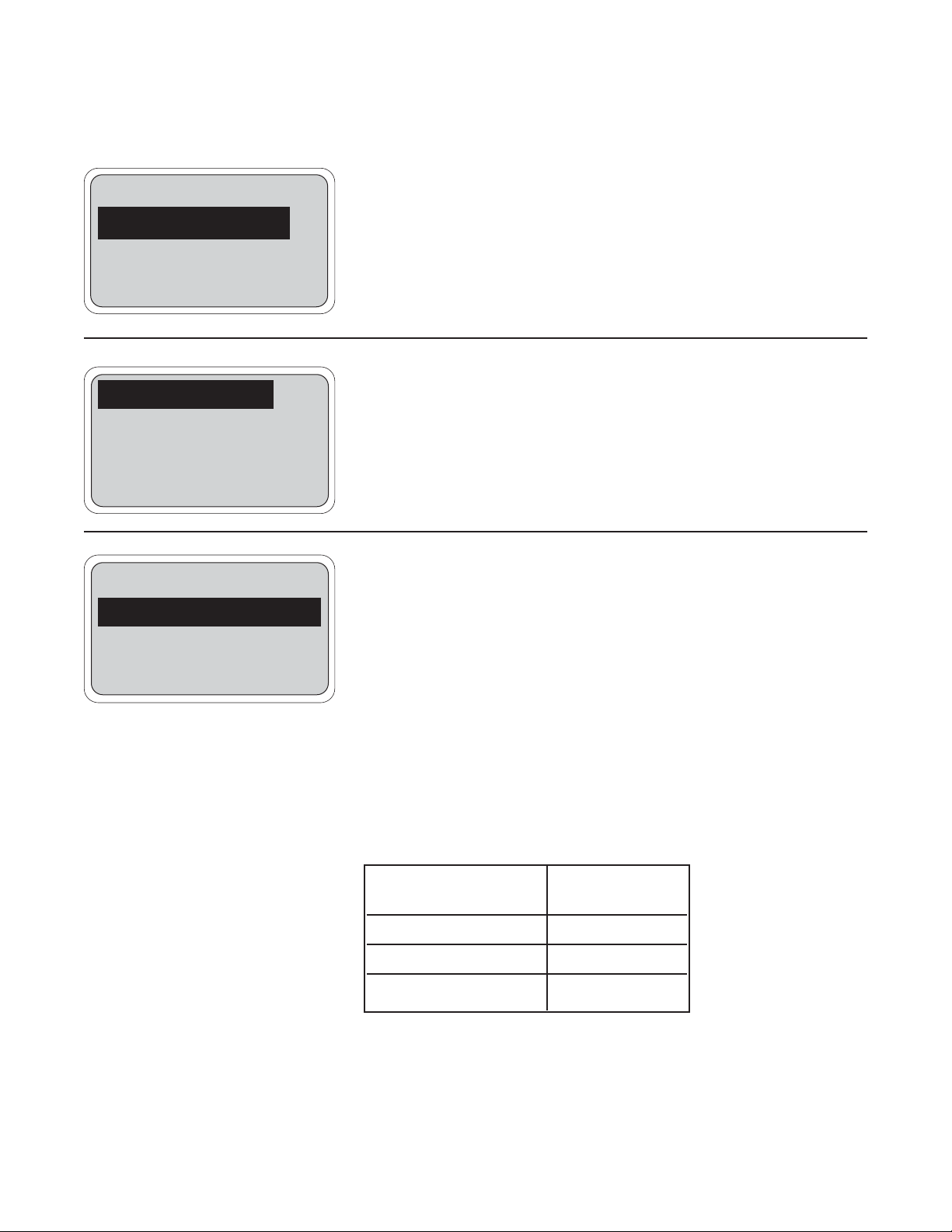
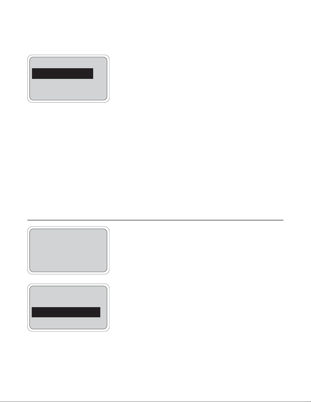
4.3 ZEROING THE CONTROLLER
MODEL 54eC SECTION 4.0
CALIBRATION
This procedure is used to compensate for small offsets to the conductivity signal that are present even when there is no conductivity to be measured. This procedure is affected by the length of extension cable and
should always be repeated if any changes in extension cable or sensor
have been made. Electrically connect the conductivity probe as it will
actually be used and place the measuring portion of the probe in air.
1. Obtain the screen above (see Section 4.2 for directions) and press
the down arrow key to highlight "Sensor Zero".
2. Press Enter 4 to access the zero routine.
3. This display indicates the conductivity reading in air. When in the
"Inductive sensor" mode, the reading is displayed to the nearest
µS/cm. When configured in the "Contacting sensor" mode, the
reading is shown to the nearest .001 µS/cm.
Verify that the sensor is actually in air. If the displayed value is not
very close to zero, then press Cont 3 and the controller will establish a
new zero. While setting the zero, the message "please wait" is displayed.
After a few seconds, the display will return to a value of 0 µS/cm and may
then change slightly. A slight variation from zero is to be expected, and
the procedure may be repeated several times, if necessary. A successful zero is indicated with a message of "Sensor zero completed"
An unsuccessful zero will result if the conductivity reading is more than
1000 µS/cm or if the reading is too unstable. The "Zero offset error" message indicates the reading is too high for the zero routine. If repeated
attempts do not result in an acceptable zero, there is a good chance that
there is a wiring problem. Check Section 8.0, Troubleshooting, for help.
Once the reading is close enough to zero, then press Exit 1 and continue initial setup by setting the temperature slope (Section 4.4) or calibrating the temperature reading (Section 4.5).
Cell constant
Sensor zero
Exit Enter
Cell constant
Sensor zero
Exit Enter
5 μS/cm
Sensor Zero
Sensor must be in air
Exit Cont
5 μS/cm
Sensor Zero
Sensor must be in air
please wait
Exit Cont
2 μS/cm
Sensor Zero
Sensor must be in air
Sensor zero completed
Exit Cont
1035 μS/cm
Sensor Zero
Sensor must be in air
Zero offset error
Exit Cont
4.4 SELECTING THE TEMPERATURE COMPENSATION TYPE
MODEL 54eC SECTION 4.0
CALIBRATION
Temperature has a significant effect on the conductivity signal. The size
of this effect depends on what kind of liquid is being measured. This procedure is used to adjust the type of compensation used by the controller.
1. Obtain the screen above (see Section 4.1 for procedure) and press
the down arrow key twice to highlight "Temp compensation".
2. Press Enter 4.
3. Press Edit 4 and use up & down arrow keys to select the appropri-
ate temperature compensation: "Linear", "Neutral Salt", or "Cation". If
"Linear" is selected, the linear slope may need adjusting (step 4).
Press 4 again to select.
For an explanation of the temperature compensation, refer to Section 6.0.
4. The compensation is in the form of a constant slope of 0-5%/°C.
Table 4-1 lists some representative values of temperature slopes.The
temperature slope currently being used by the controller is shown
here. If this value is acceptable, press Exit 1. 2%/°C is a good
value for natural waters. For more specialized applications, use the
representative values of Table 4-1. To change the temperature slope,
press Edit 4.
As before, the Edit key changes to the Save key and the F3 key now has
become the Esc(ape) key. Use the four arrow keys to change to the correct temperature slope for your process. Once the correct value is
shown, press Save 4 to enter it into memory. Press Esc 3 to cancel.
Adjust temperature
Temp compensation
Initial setup
Exit Enter
Comp type: Linear
Linear slope: 2.00%/°C
Auto temp: On
Exit Enter
Comp type: Linear
Linear slope: 2.00%/°C
Auto temp: On
Exit Enter
TABLE 4-1. Typical Temperature Slopes
Chemical Slope (%/°C)
Cleaner (alkaline) 2.25
Cleaner (acid) 1.4
Conversion coating 1.6
15
16
4.5 TEMPERATURE CALIBRATION
MODEL 54eC SECTION 4.0
CALIBRATION
This procedure is used to ensure an accurate temperature measurement
by the temperature sensor. It enables the controller to display process
temperature accurately as well as to compensate for the effect of temperature on the conductivity reading when the temperature in your
process changes. The following steps should be performed with the sensor in the process or in a grab sample near the operating temperature.
1. Check the controller temperature reading (main display) to make sure
the sensor has acclimated to the process temperature. Compare the
controller temperature to a calibrated temperature reading device.
Proceed to the next step if the reading requires adjustment.
2. From the main display, press any key and then press Enter 4 to
access the Calibrate menu.
NOTE
The hold mode screen may appear (as in Section 4.1) if
the hold mode was enabled in Section 5.6. See note on
Section 4.1 for instructions.
Press the arrow key once to bring up the screen to the left.
Then press Enter 4.
NOTE
(To verify that the controller is using automatic temperature compensation, highlight the "Temp compensation"
menu item and press Enter 4. For more details, see
Section 4.7)
3. Press Edit 4 with this display shown to adjust the temperature. The
screen below will then appear. Using the arrow keys, input the correct temperature value and press Save 4. The controller will enter
the value into memory. To abort the change, press Esc 3.
Afterwards, go to Section 4.6 to standardize the conductivity, otherwise press Exit 1 three times for the main display.
NOTE
If hold mode was turned ON, be certain to install the sensor back in the process and change the setting to OFF to
resume normal operation before leaving the controller.
The Hold screen will appear again before the main display is shown. Follow the same routine as in the Note for
Section 4.1 to turn the Hold Mode Off and then press Exit
1.
Calibrate sensor
Adjust temperature
Temp compensation
Exit Enter
25.1 °C
Adjust temp: 25.1°C
Exit Enter
25.1 °C
Adjust temp: +25.1°C
Exit Enter

4.6 CALIBRATING THE SENSOR
MODEL 54eC SECTION 4.0
CALIBRATION
This procedure is used to check and correct the conductivity reading of
the Model 54eC to ensure that the reading is accurate. This is done by
submerging the probe in the sample of known conductivity, then adjusting the displayed value, if necessary, to correspond to the conductivity
value of the sample.
This procedure must always be done after cleaning the probe. The temperature reading must also be checked and standardized if necessary,
prior to performing this procedure (see Section 4.5).
Important: If you are submerging the probe in the commercial conductivity standard solution, follow steps 1 through 3. If you are leaving the probe submerged in the bath and checking conductivity
against a laboratory instrument skip steps 1-3 and start at step 4.
1. Be sure that the probe has been cleaned of heavy deposits of dirt,
oils, or chemical residue.
2. Commercial standards are referenced to a known temperature, for
example, 4000 micromhos at 25°C (77°F). As the temperature of the
standard changes, the conductivity will change. Therefore it is recommended that this procedure be performed at a temperature
between 22 and 28 °C. Be sure the probe has reached a stable
temperature before standardizing.
3. Pour the standard into a clean container. Submerge the clean probe
in the standard solution. Place the probe so that a minimum of 1 in.
of liquid surrounds the probe. Do not allow the probe to be closer
than 1 in. to the sides or bottom of the container. Shake the probe
slightly to eliminate any trapped air bubbles. Observe the displayed
conductivity to determine if the sensor needs to be moved. Go to step
6.
4. Take a grab sample that is as close to the sensor as possible.
5. Using a calibrated laboratory instrument with automatic tempera-
ture compensation, determine the conductivity of the process or
grab sample (as close to actual process temperature as possible).
Continue with this procedure if an adjustment is needed.
Next, the steps below allow you to change the controller's displayed conductivity reading to match the known value of conductivity of your sample.
6. From the main display, press any key to obtain the main menu. With
the cursor on "Calibrate", press Enter 4. Press Enter 4 again
when the screen to the left appears.
NOTE
The Hold Mode screen may appear if the feature was
enabled in Section 5.6. Changing the Hold Mode to ON
holds the outputs in a fixed state, and avoids process
upsets during calibration. Remember to change the Hold
Mode back to OFF when calibration is completed.
Calibrate sensor
Adjust temperature
Temp compensation
Exit Enter
17
 Loading...