


Model 4081C
Remote Controlled FOUNDATION
™
Fieldbus
Two-Wire Conductivity Transmitter
Instruction Manual
PN 51-4081C/rev.C
June 2002

ESSENTIAL INSTRUCTIONS
READ THIS PAGE BEFORE PROCEEDING!
Rosemount Analytical designs, manufactures, and tests its products to meet
many national and international standards. Because these instruments are
sophisticated technical products, you must properly install, use, and maintain
them to ensure they continue to operate within their normal specifications. The
following instructions must be adhered to and integrated into your safety
program when installing, using, and maintaining Rosemount Analytical
products. Failure to follow the proper instructions may cause any one of the
following situations to occur: Loss of life; personal injury; property damage;
damage to this instrument; and warranty invalidation.
• Read all instructions prior to installing, operating, and servicing the product.
If this Instruction Manual is not the correct manual, telephone 1-800-6547768 and the requested manual will be provided. Save this Instruction
Manual for future reference.
• If you do not understand any of the instructions, contact your Rosemount
representative for clarification.
• Follow all warnings, cautions, and instructions marked on and supplied with
the product.
• Inform and educate your personnel in the proper installation, operation, and
maintenance of the product.
• Install your equipment as specified in the Installation Instructions of the
appropriate Instruction Manual and per applicable local and national codes.
Connect all products to the proper electrical and pressure sources.
• To ensure proper performance, use qualified personnel to install, operate,
update, program, and maintain the product.
• When replacement parts are required, ensure that qualified people use
replacement parts specified by Rosemount. Unauthorized parts and
procedures can affect the product’s performance and place the safe
operation of your process at risk. Look alike substitutions may result in fire,
electrical hazards, or improper operation.
• Ensure that all equipment doors are closed and protective covers are in
place, except when maintenance is being performed by qualified persons, to
prevent electrical shock and personal injury.
Emerson Process Management
Rosemount Analytical Inc.
2400 Barranca Parkway
Irvine, CA 92606 USA
Tel: (949) 757-8500
Fax: (949) 474-7250
http://www.RAuniloc.com
© Rosemount Analytical Inc. 2001

TABLE OF CONTENTS
Section Title Page
1.0 INSTALLATION................................................................................................................. 1-1
1.1 Overview .................................................................................................................. 1-1
1.2 Mechanical Installation............................................................................................. 1-2
1.3 Electrical Installation ................................................................................................ 1-4
2.0 OPERATION OVERVIEW ................................................................................................. 2-1
2.1 General .................................................................................................................... 2-1
2.2 Display ..................................................................................................................... 2-1
2.3 Infrared Remote Control (IRC)................................................................................. 2-2
2.4 Diagnostic Messages............................................................................................... 2-2
2.5 Menu Program Tree................................................................................................. 2-3
3.0 FACTORY PROGRAMMED SETTINGS ........................................................................... 3-1
4.0 TRANSMITTER PROGRAM SET-UP ............................................................................... 4-1
4.1 Program Menu ......................................................................................................... 4-1
4.2 Temperature Parameters ......................................................................................... 4-2
4.3 Display Units ............................................................................................................ 4-3
5.0 START-UP AND CALIBRATION....................................................................................... 5-1
5.1 Accessing The Calibrate Menu ................................................................................ 5-1
5.2 Calibrate Menu ........................................................................................................ 5-2
5.3 Calibrate Menu (Contacting) .................................................................................... 5-3
5.4 Branch Calibration Initial Start-Up............................................................................ 5-4
5.5 Calibrate Menu (Low Conductivity/Resistivity)......................................................... 5-5
5.6 On-line Calibration ................................................................................................... 5-6
6.0 DIAGNOSIS AND TROUBLESHOOTING ........................................................................ 6-1
6.1 Overview .................................................................................................................. 6-1
6.2 Fault Conditions ....................................................................................................... 6-3
6.3 Diagnostic Messages............................................................................................... 6-4
6.4 Quick Troubleshooting Guide................................................................................... 6-5
6.5 Systematic Troubleshooting..................................................................................... 6-6
6.6 RTD Resistance Values ........................................................................................... 6-7
7.0 MAINTENANCE ................................................................................................................ 7-1
7.1 Overview .................................................................................................................. 7-1
7.2 Preventative Maintenance ....................................................................................... 7-1
7.3 Corrective Maintenance ........................................................................................... 7-1
8.0 PRODUCT DATA............................................................................................................... 8-1
8.1 Features................................................................................................................... 8-1
8.2 Specifications........................................................................................................... 8-2
8.3 Transmitter Display .................................................................................................. 8-3
8.4 Infrared Remote Control Functions.......................................................................... 8-3
8.5 Ordering Information ................................................................................................ 8-4
9.0 OPERATION WITH REMOTE CONTROLLER ................................................................. 9-1
10.0 RETURN OF MATERIALS ................................................................................................ 10-1
i
MODELS 4081C TABLE OF CONTENTS
MODEL 4081C
MICROPROCESSOR ANALYZERS

ii
LIST OF FIGURES
Figure No. Title Page
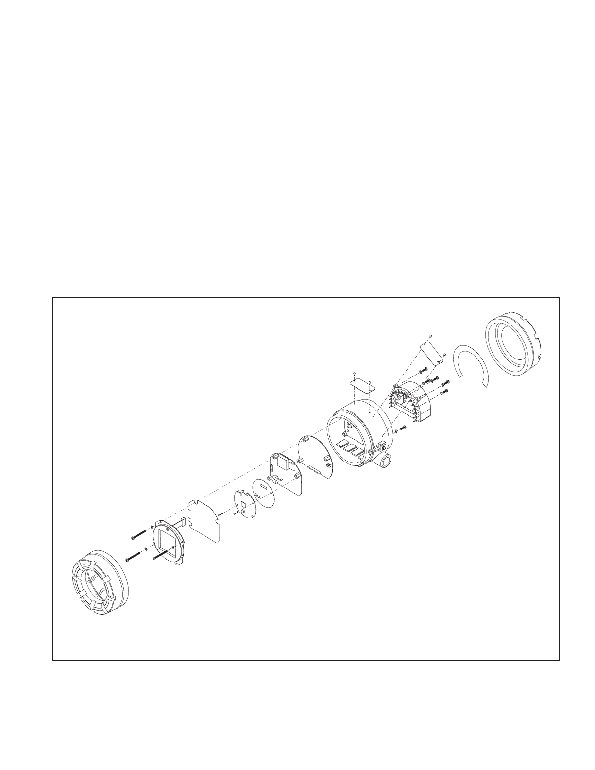
1-1 Exploded Drawing of Circuit Board Stack . . . . . . . . . . . . . . . . . . . . . . . . . . . . . . . . . 1-1
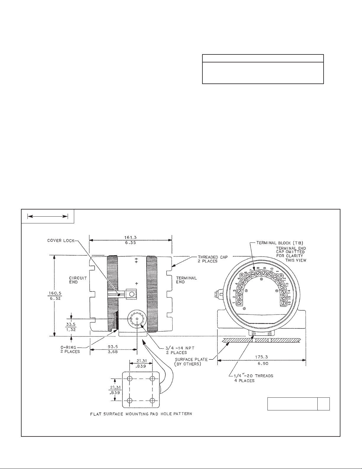
1-2 Dimensional Information - Model 4081C . . . . . . . . . . . . . . . . . . . . . . . . . . . . . . . . . . 1-2
1-3 Mounting Information - Model 4081C . . . . . . . . . . . . . . . . . . . . . . . . . . . . . . . . . . . . 1-3
1-4 Contacting Conductivity Sensor Wiring to Model 4081C Transmitter . . . . . . . . . . . . 1-6
1-5 Sensor Wiring with Pre-existing Conductivity Sensors . . . . . . . . . . . . . . . . . . . . . . . 1-7
1-6 Model 4081C Terminal Blocks . . . . . . . . . . . . . . . . . . . . . . . . . . . . . . . . . . . . . . . . . . 1-8
1-7 Typical Fieldbus Network Electrical Wiring Configuration . . . . . . . . . . . . . . . . . . . . . 1-8
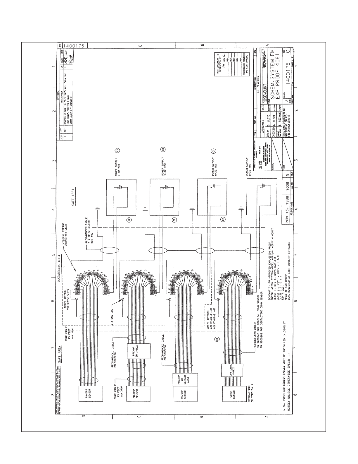
1-8 FM Explosion Proof Installation . . . . . . . . . . . . . . . . . . . . . . . . . . . . . . . . . . . . . . . . . 1-9
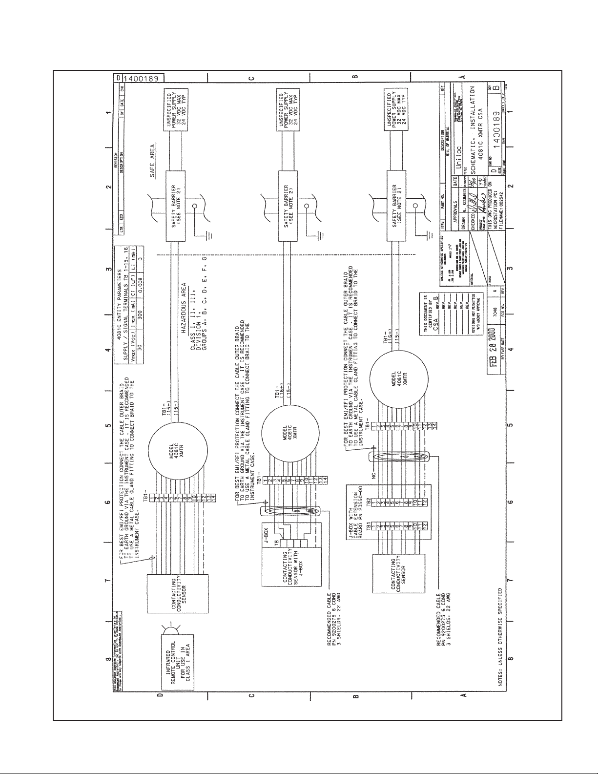
1-9 CSA Intrinsically Safe Installation . . . . . . . . . . . . . . . . . . . . . . . . . . . . . . . . . . . . . . . 1-11
1-10 FMRC Intrinsically Safe Installation . . . . . . . . . . . . . . . . . . . . . . . . . . . . . . . . . . . . . 1-13
2-1 Process Display Screen . . . . . . . . . . . . . . . . . . . . . . . . . . . . . . . . . . . . . . . . . . . . . . 2-1
2-2 Program Mode Display Areas . . . . . . . . . . . . . . . . . . . . . . . . . . . . . . . . . . . . . . . . . . 2-1
2-3 Infrared Remote Control . . . . . . . . . . . . . . . . . . . . . . . . . . . . . . . . . . . . . . . . . . . . . . 2-2
2-4 Menu Tree . . . . . . . . . . . . . . . . . . . . . . . . . . . . . . . . . . . . . . . . . . . . . . . . . . . . . . . . . 2-3
4-1 Program Menu and Menu Segments . . . . . . . . . . . . . . . . . . . . . . . . . . . . . . . . . . . . 4-1
4-2 RTD Sensor Connections . . . . . . . . . . . . . . . . . . . . . . . . . . . . . . . . . . . . . . . . . . . . . 4-2
4-3 Security Code Prompt . . . . . . . . . . . . . . . . . . . . . . . . . . . . . . . . . . . . . . . . . . . . . . . . 4-4
5-1 Calibration Menu Segments . . . . . . . . . . . . . . . . . . . . . . . . . . . . . . . . . . . . . . . . . . . 5-1
6-1 Diagnose Menu Segments . . . . . . . . . . . . . . . . . . . . . . . . . . . . . . . . . . . . . . . . . . . . 6-1
6-2 Diagnose Values . . . . . . . . . . . . . . . . . . . . . . . . . . . . . . . . . . . . . . . . . . . . . . . . . . . . 6-2
6-3 Disabling Fault Annunciation . . . . . . . . . . . . . . . . . . . . . . . . . . . . . . . . . . . . . . . . . . . 6-3
6-4 Non-disabling Warning Annunciation . . . . . . . . . . . . . . . . . . . . . . . . . . . . . . . . . . . . 6-3
6-5 Troubleshooting Flow Chart . . . . . . . . . . . . . . . . . . . . . . . . . . . . . . . . . . . . . . . . . . . 6-6
7-1 Hold Annunciation . . . . . . . . . . . . . . . . . . . . . . . . . . . . . . . . . . . . . . . . . . . . . . . . . . . 7-1
7-2 Exploded View of Model 4081C Transmitter . . . . . . . . . . . . . . . . . . . . . . . . . . . . . . . 7-2
8-1 Transmitter Display . . . . . . . . . . . . . . . . . . . . . . . . . . . . . . . . . . . . . . . . . . . . . . . . . . 8-3
8-2 Infrared Remote Control . . . . . . . . . . . . . . . . . . . . . . . . . . . . . . . . . . . . . . . . . . . . . . 8-3
8-3 Functional Block Diagram for Model 4081C Transmitter with F
OUNDATION Fieldbus . 8-3
9-1 Functional Block Diagram for Model 4081C Transmitter with FOUNDATION Fieldbus . 9-1
LIST OF TABLES
Table No. Title Page
1-1 Measurement Range . . . . . . . . . . . . . . . . . . . . . . . . . . . . . . . . . . . . . . . . . . . . . . . . . 1-4
1-2 Transmitter Range Limits (Ultra Pure) . . . . . . . . . . . . . . . . . . . . . . . . . . . . . . . . . . . . 1-4
1-3 Transmitter Range Limits (Resistivity) . . . . . . . . . . . . . . . . . . . . . . . . . . . . . . . . . . . . 1-5
1-4 Transmitter Range Limits (Conductivity) . . . . . . . . . . . . . . . . . . . . . . . . . . . . . . . . . . 1-5
3-1 Program Variables with Factory Settings . . . . . . . . . . . . . . . . . . . . . . . . . . . . . . . . . 3-1
4-1 Transmitter Settings . . . . . . . . . . . . . . . . . . . . . . . . . . . . . . . . . . . . . . . . . . . . . . . . . 4-3
4-2 Program Menu Mnemonics . . . . . . . . . . . . . . . . . . . . . . . . . . . . . . . . . . . . . . . . . . . . 4-4
5-1 Calibrate Menu Mnemonics . . . . . . . . . . . . . . . . . . . . . . . . . . . . . . . . . . . . . . . . . . . 5-6
6-1 Diagnostics Variables Mnemonics . . . . . . . . . . . . . . . . . . . . . . . . . . . . . . . . . . . . . . 6-2
6-2 Diagnostic Fault Messages . . . . . . . . . . . . . . . . . . . . . . . . . . . . . . . . . . . . . . . . . . . . 6-4
6-3 Quick Troubleshooting Guide . . . . . . . . . . . . . . . . . . . . . . . . . . . . . . . . . . . . . . . . . . 6-5
6-4 RTD Resistance Values . . . . . . . . . . . . . . . . . . . . . . . . . . . . . . . . . . . . . . . . . . . . . . 6-7
6-5 Conductivity Determination . . . . . . . . . . . . . . . . . . . . . . . . . . . . . . . . . . . . . . . . . . . . 6-7
7-1 Replacement Parts for Model 4081C Transmitter . . . . . . . . . . . . . . . . . . . . . . . . . . . 7-2
LIST OF APPENDICES
Section Title Page
A Glossary . . . . . . . . . . . . . . . . . . . . . . . . . . . . . . . . . . . . . . . . . . . . . . . . . . . . . . . . . . A-1
B 4081C Resource and Transducer Block Parameters. . . . . . . . . . . . . . . . . . . . . . . . . B-1
MODELS 4081C TABLE OF CONTENTS
MODELS 4081C SECTION 1.0
INSTALLATION
SECTION 1.0
INSTALLATION
FIGURE 1-1. Model 4081C Transmitter - Exploded Drawing of Circuit Board Stack
1.1 OVERVIEW
This conductivity transmitter has been designed for
easy installation and shipment. The purpose of this
section is to provide information on the electrical configurations and the physical mountings available. Prior
to discarding the packing case:
If it is damaged, the transmitter may have also
sustained damage. Contact the carrier at once.
Remove all items shown on the packing list and
note any exceptions.
1-1
The Model 4081C conductivity transmitter is designed
to make accurate measurements while the sensor is
submersed in the process stream. Measurements can
also be tailored to high temperature and/or high pressure streams. The specific ranges covered are controlled by both hardware and software.
1-2
FIGURE 1-2. Dimensional Information – Model 4081C
DWG. NO. REV.
44081C01 A
MILLIMETER
INCH
MODELS 4081C SECTION 1.0
INSTALLATION
1.2 MECHANICAL INSTALLATION
The Model 4081C Transmitter is suitable for installation in
harsh environments.
• For best operation, locate in an area where temperature extremes, vibrations, electromagnetic, and radio
frequency interferences are minimized or absent.
The transmitter is equipped with two 3/4 in. FNPT conduit
openings, one on each side of the transmitter housing.
• Remove the terminal end cap.
• With the transmitter positioned with the wiring terminal
side of the enclosure opened (as seen in Figure 1-2),
use the left conduit opening to bring in the sensor
wiring, and the right side conduit opening for power
supply/current loop wiring.
• To prevent moisture from entering the transmitter
housing, use weathertight cable glands supplied by
others.
NOTE
Moisture accumulation in the transmitter
housing can affect transmitter performance
and may void its warranty.
• If conduit is used, connections on the transmitter housing should be plugged and sealed (with tape, pipe compound, or sealant) to prevent moisture accumulation in
the terminal side of the housing.
• The transmitter must be installed so that the conduit
openings are not on the top, because moisture can
accumulate in that position.
• The transmitter should be easily accessed by operating
and maintenance personnel.
1.2.1 Flat Surface Mounting. The transmitter may be
mounted on a flat surface (see Figure 1-2) using the threaded mounting holes on the bottom of the transmitter.
1.2.2 Pipe Mounting Bracket. An optional pipe mounting
bracket is available. See Figure 1-3 for mounting information.

1-3
MODELS 4081C SECTION 1.0
INSTALLATION
FIGURE 1-3. Mounting Information - Model 4081C
DWG. NO. REV.
40408103 B
DWG. NO. REV.
40408104 F
MILLIMETER
INCH

1-4
MODELS 4081C SECTION 1.0
INSTALLATION
1.3 ELECTRICAL INSTALLATION
1.3.1 Conductivity Sensors
All Rosemount Analytical Inc.’s contacting conductivity
sensors with Pt100 RTD or Pt1000 RTD are compatible
with the Model 4081C transmitter.
NOTE
Optimum EMI/RFI immunity may be achieved on
sensors whose interconnecting cable has an outer
braided shield by utilizing a cable gland fitting that
provides for continuity between the braided shield
and the transmitter enclosure. An equivalent conduit connector may also be used if the sensor
cable is to be enclosed in conduit.
1.3.2 Contacting Loops.
The Model 4081C conductivity transmitter is designed to
make accurate measurements while in contact with the
process stream. Measurements can also be tailored to high
temperature and/or high pressure streams. The following
table shows the measurement ranges and linearity available for each range and cell constant.
TABLE 1-1. Measurement Ranges (µs/cm)
TABLE 1-2. Transmitter Range Limits (Ultra Pure [PV_HIGH_LOW_RANGE = Low])
CELL CONSTANT 0.01 0.10 1.0
Low Range 0-20 0-200 0-2,000
(linearity: ± 1.0%)
High Range 0-200 0-2,000 0-20,000
(linearity: ± 5.0%)
Wire Terminal
Connection
(11) or (12)
*NOTE: Values shown are the 25°C conductivity with a tem-
perature slope of 2% per degree C. The maximum
range value will be higher for solutions with a lower
temperature slope, and lower for solutions with a
higher temperature slope.
NOTE: Connect grey (or black) wire of sensor to TB-11 for
high conductivity ranges or to TB-12 for low conductivity ranges.
MANUAL_AUTO_RANGE RANGE_VALUE CELL_CONSTANT (0% FS) (100% FS)
Manrng (1/cm) EU0% µS/cm EU100% µS/cm
Auto N/A 0.01 0 20
Auto N/A 0.1 0 200
Auto N/A 1.0 0 2,000
Manual 1 0.01 0 0.0975
Manual 1 0.1 0 0.975
Manual 1 1.0 0 9.75
Manual 2 0.01 0 0.64
Manual 2 0.1 0 6.4
Manual 2 1.0 0 64
Manual 3 0.01 0 4.05
Manual 3 0.1 0 40.5
Manual 3 1.0 0 405
Manual 4 0.01 0 20
Manual 4 0.1 0 200
Manual 4 1.0 0 2,000

MODELS 4081C SECTION 1.0
INSTALLATION
1-5
TABLE 1-3. Transmitter Range Limits (Resistivity [PV_HIGH_LOW_RANGE = Low])
MANUAL_AUTO_RANGE RANGE_VALUE CELL_CONSTANT (0% FS) (100% FS)
Manrng (1/cm) EU0% (MΩ-cm) EU100% (MΩ-cm)
Auto N/A 0.01 0.05 50
Auto N/A 0.1 0.005 50
Auto N/A 1.0 0.0005 50
Manual 1 0.01 10.3 50
Manual 1 0.1 1.03 50
Manual 1 1.0 0.103 50
Manual 2 0.01 1.56 50
Manual 2 0.1 0.156 50
Manual 2 1.0 0.0156 50
Manual 3 0.01 0.247 50
Manual 3 0.1 0.0247 50
Manual 3 1.0 0.00247 50
Manual 4 0.01 0.05 50
Manual 4 0.1 0.005 50
Manual 4 1.0 0.0005 50
TABLE 1-4. Transmitter Range Limits (Linear Conductivity)
PV_HIGH_LOW_RANGE MANUAL_AUTO_RANGE RANGE_VALUE CELL_CONSTANT (0% FS) (100% FS)
Manrng
(1/cm) EU0% µS/cm EU100% µS/cm
Low Auto N/A 0.01 0 20
Low Auto N/A 0.1 0 200
Low Auto N/A 1.0 0 2,000
High Auto N/A 0.01 0 200
High Auto N/A 0.1 0 2,000
High Auto N/A 1.0 0 20,000
Low Manual 1 0.01 0 0.0975
Low Manual 1 0.1 0 0.975
Low Manual 1 1.0 0 9.75
Low Manual 2 0.01 0 0.64
Low Manual 2 0.1 0 6.40
Low Manual 2 1.0 0 64
Low Manual 3 0.01 0 4.05
Low Manual 3 0.1 0 40.5
Low Manual 3 1.0 0 405
Low Manual 4 0.01 0 20
Low Manual 4 0.1 0 200
Low Manual 4 1.0 0 2,000
High Manual 1 0.01 0 8
High Manual 1 0.1 0 80
High Manual 1 1.0 0 800
High Manual 2 0.01 0 52
High Manual 2 0.1 0 520
High Manual 2 1.0 0 5,200
High Manual 3 0.01 0 200
High Manual 3 0.1 0 2,000
High Manual 3 1.0 0 20,000

1-6
MODELS 4081C SECTION 1.0
INSTALLATION
*
Note: Connect grey wire of sensor to TB-11 for high conductivity ranges or to TB-12 for low conductivity ranges. See
Table 1-2 for range selection.
FIGURE 1-4. Contacting Conductivity Sensor to Model 4081C Transmitter

1-7
MODELS 4081C SECTION 1.0
INSTALLATION
FIGURE 1-5. Sensor Wiring with Pre-existing Conductivity Sensors

1-8
MODELS 4081C SECTION 1.0
INSTALLATION
FIGURE 1-6. MODEL 4081C TERMINAL BLOCKS
MODEL 4081C
FIGURE 1-7. TYPICAL FIELDBUS NETWORK ELECTRICAL WIRING CONFIGURATION

MODELS 4081C SECTION 1.0
INSTALLATION
LABEL, I.S. N.I. & EX CSA APPROVED FOR MODEL 4081C
1-9
1.3.3 Hazardous Area Installation
In order to maintain the hazardous area rating for installed transmitter, the following drawings must be used:
Figure 1-8. Wiring for FM Explosion-Proof Installation for Model 4081C (Drawing Number 1400175)
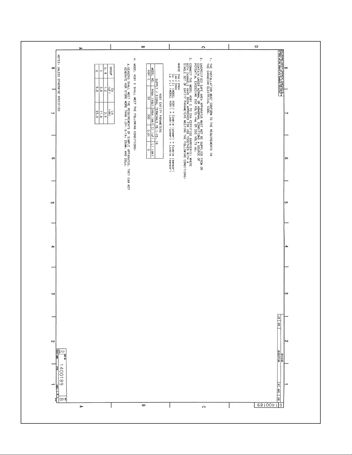
Figure 1-9. Wiring for CSA Intrinsic Safety for Model 4081C (Drawing Number 1400189). See also label below.
Figure 1-10. Wiring for FMRC Instrinsically Safe Installation for Model 4081C (Drawing Number 1400186).
1-10
MODELS 4081C SECTION 1.0
INSTALLATION
FIGURE 1-8. EXPLOSION-PROOF INSTALLATION
MODELS 4081C SECTION 1.0
INSTALLATION
FIGURE 1-9. CSA INTRINSICALLY SAFE INSTALLATION (1 of 2)
1-11
1-12
MODELS 4081C SECTION 1.0
INSTALLATION
FIGURE 1-9. CSA INTRINSICALLY SAFE INSTALLATION (2 of 2)

MODELS 4081C SECTION 1.0
INSTALLATION
FIGURE 1-10. FMRC INTRINSICALLY SAFE INSTALLATION (1 of 2)
1-13

1-14
MODELS 4081C SECTION 1.0
INSTALLATION
FIGURE 1-10. FMRC INTRINSICALLY SAFE INSTALLATION (2 of 2)

2-1
2.1 GENERAL
The Model 4081C transmitter operates in either the
Process or Program modes. The process mode screen
is illustrated in Figure 2-1 and the program mode screen
is illustrated in Figure 2-2.
2.2 DISPLAY
2.2.1 Process Mode (normal operating mode). When
operating in this mode:
• The primary process variable (the conductivity) is
continuously displayed (see 1 in Figure 2-1)
• Engineering units are determined by the process
display mode
• Temperature output is in °F or °C (see 2 in Figure 2-1)
2.2.2 Program Mode (programming or calibrating
mode — step-by-step instructions for programming
and calibrating the transmitter are given in Sections
4.0 and 5.0, respectively). When operating in this mode
the following information is provided on the instrument
display:
• Continuous display of the primary process variable
is still available.
• Menus are displayed below the process variable.
The active subset title is in bold print (see 1 in
Figure 2-2).
CALIBRATE PROGRAM DIAGNOSE
CALIbrAtE
EXIT NEXT ENTER
1000
mS/cm
F
A
U
L
T
H
O
L
D
5
4
1
3
MODELS 4081C SECTION 2.0
OPERATION OVERVIEW
SECTION 2.0
OPERATION OVERVIEW
2
FIGURE 2-1. Process Display Screen
11000000
mS/cm
25.0C
FIGURE 2-2. Program Mode Display Areas
• Security ID (see Section 4.3, step 10) and prompts
are displayed below the segments (see 2 and 3 in
Figure 2-2).
• FAULT is displayed (see 4 in Figure 2-2) when a
transmitter disabling condition occurs. When in the
fault mode, the fault indicator lights up and the
process variable flashes. The program mode must
be entered to see the descriptive fault message.
• HOLD (see 5 in Figure 2-2) becomes visible when-
ever the transmitter is placed in the hold, test, or
multidrop function. Hold is most often used when
servicing/cleaning the sensor.
2
1
 Loading...