

Manual: 4081FG 2-Wire In Situ O2 Analyzer (550° to 1600°C) with FOUNDATION Fieldbus Communications-Rev 1.2 | Rosemount
Table of contents
 Loading...
Rosemount Manual: 4081FG 2-Wire In Situ O2 Analyzer (550° to 1600°C) with FOUNDATION Fieldbus Communications-Rev 1.2 | Rosemount Manuals & Guides
Instruction Manual
IB-106-4081 Rev. 1.2
September, 2002
Model 4081FG
Two-Wire In Situ Oxygen Analyzer
(550° to 1600°C) with F
OUNDATION
Fieldbus Communications
http://www.processanalytic.com

ESSENTIAL INSTRUCTIONS
READ THIS PAGE BEFORE PROCEEDING!
Rosemount Analytical designs, manufactures and tests its products to meet many national and
international standards. Because these instruments are sophisticated technical products, you
MUST properly install, use, and maintain them to ensure they continue to operate within their
normal specifications. The following instructions MUST be adhered to and integrated into your
safety program when installing, using, and maintaining Rosemount Analytical products. Failure to
follow the proper instructions may cause any one of the following situations to occur: Loss of life;
personal injury; property damage; damage to this instrument; and warranty invalidation.
• Read all instructions prior to installing, operating, and servicing the product.
• If you do not understand any of the instructions, contact your Rosemount Analytical repre-
sentative for clarification.
• Follow all warnings, cautions, and instructions marked on and supplied with the product.
• Inform and educate your personnel in the proper installation, operation, and mainte-
nance of the product.
• Install your equipment as specified in the Installation Instructions of the appropriate In-
struction Manual and per applicable local and national codes. Connect all products to the
proper electrical and pressure sources.
• To ensure proper performance, use qualified personnel to install, operate, update, program,
and maintain the product.
• When replacement parts are required, ensure that qualified people use replacement parts
specified by Rosemount. Unauthorized parts and procedures can affect the product’s performance, place the safe operation of your process at risk, and VOID YOUR WARRANTY.
Look-alike substitutions may result in fire, electrical hazards, or improper operation.
• Ensure that all equipment doors are closed and protective covers are in place, except
when maintenance is being performed by qualified persons, to prevent electrical shock
and personal injury.
The information contained in this document is subject to change without notice.
Emerson Process Management
Rosemount Analytical Inc.
Process Analytic Division
1201 N. Main St.
Orrville, OH 44667-0901
T (330) 682-9010
F (330) 684-4434
e-mail: gas.csc@EmersonProcess.com
http://www.processanalytic.com

HIGHLIGHTS OF CHANGES
Effective April, 2001 Rev. 1.0
Page Summary
Throughout Changed all references of 38 in. (965 mm) probe to 34.625 in. (880 mm).
Page 11-2 Added drawing 1400175.
Effective December, 2001 Rev. 1.1
Page Summary
Page 1-3 Updated Product Matrix.
Effective September, 2002 Rev. 1.2
Page Summary
Page 1-8 Updated process temperature limits specification.


Model 4081FG
PREFACE........................................................................................................................ P-1
Definitions ........................................................................................................................P-1
Safety Instructions .......................................................................................................... P-2
1-0 DESCRIPTION AND SPECIFICATIONS........................................................................ 1-1
1-1 Component Checklist of Typical System (Package Contents) .................................. 1-1
1-2 System Overview............................................................................................................ 1-1
1-3 Specifications................................................................................................................... 1-8
2-0 INSTALLATION .............................................................................................................. 2-1
2-1 Pre-Installation................................................................................................................. 2-1
2-2 Mechanical Installation ................................................................................................... 2-1
2-3 Electrical Installation.....................................................................................................2-10
2-4 Pneumatic Installation .................................................................................................. 2-11
3-0 STARTUP........................................................................................................................ 3-1
3-1 General ............................................................................................................................ 3-1
3-2 Power Up........................................................................................................................ 3-1
3-3 Reestablishing Proper Calibration Check Gas Flow Rate......................................... 3-2
Instruction Manual
IB-106-4081 Rev. 1.2
September, 2002
TABLE OF CONTENTS
4-0 OPERATION ...................................................................................................................4-1
4-1 General ............................................................................................................................ 4-1
4-2 Program Menu ................................................................................................................4-4
4-3 Diagnostics Menu ........................................................................................................... 4-8
4-4 CALCHECK MENU ...................................................................................................... 4-12
4-5 SIMULATE SWITCH .................................................................................................... 4-15
4-6 SECURITY SWITCH .................................................................................................... 4-15
5-0 MAINTENANCE AND SERVICE .................................................................................. 5-1
5-1 MODEL 4081 ELECTRONICS REPLACEMENT ........................................................... 5-1
5-2 OXYGEN PROBE REPLACEMENT ............................................................................. 5-2
6-0 TROUBLESHOOTING .................................................................................................... 6-1
6-1 GENERAL........................................................................................................................ 6-1
6-2 PROBE LIFE.................................................................................................................... 6-1
6-3 FAULT INDICATIONS .................................................................................................... 6-2
6-4 IDENTIFYING AND CORRECTING FAULT INDICATIONS ....................................... 6-3
7-0 RETURN OF MATERIAL .............................................................................................. 7-1
8-0 REPLACEMENT PARTS ............................................................................................... 8-1
9-0 APPENDICES ................................................................................................................. 9-1
10-0 INDEX............................................................................................................................ 10-1
11-0 DRAWINGS AND SCHEMATICS............................................................................... 11-1
Rosemount Analytical Inc. A Division of Emerson Process Management i

Instruction Manual
IB-106-4081 Rev. 1.2
September, 2002
Figure 1-1. Typical System Package ....................................................................................... 1-2
Figure 1-2. Two-Wire In Situ Oxygen Analyzer Fieldbus Connections .................................... 1-7
Figure 1-3. Typical System Installation .................................................................................... 1-7
Figure 2-1. Probe Installation Details ....................................................................................... 2-2
Figure 2-2. Optional Adapter Plate........................................................................................... 2-2
Figure 2-3. Optional Probe Mounting Flange ........................................................................... 2-3
Figure 2-4. Horizontal Probe Installation .................................................................................. 2-4
Figure 2-5. Adjusting Probe Insertion Depth ............................................................................ 2-5
Figure 2-6. Flat Surface Mounting Dimensional Information.................................................... 2-7
Figure 2-7. Pipe Mounting Dimensional Information................................................................ 2-8
Figure 2-8. Display Positioning Assembly................................................................................ 2-9
Figure 2-9. Oxygen Probe Terminal Block ............................................................................. 2-11
Figure 2-10. Model 4081 Transmitter Terminal Block.............................................................. 2-11
Figure 2-11. Oxygen Probe Gas Connections ......................................................................... 2-12
Figure 2-12. Air Set, Plant Air Connection ............................................................................... 2-12
Figure 3-1. Normal Operation Display...................................................................................... 3-1
Figure 3-2. Faulted Operation Display ..................................................................................... 3-1
Figure 3-3. Proper Calibration Check Gas Flow Rate.............................................................. 3-2
Figure 4-1. Normal Operation Display...................................................................................... 4-1
Figure 4-2. Model 4081 Transmitter Menu Tree ...................................................................... 4-2
Figure 4-3. Infrared Remote Control (IRC)............................................................................... 4-3
Figure 4-4. CODE..................................................................................................................... 4-4
Figure 4-5. DISPLAY CODE ................................................................................................... 4-5
Figure 4-6. CELL T HI ............................................................................................................ 4-5
Figure 4-7. RESET MAX CELL T.......................................................................................... 4-6
Figure 4-8. SET O
Figure 4-9. SET HI BOTTLE O
Figure 4-10. SET LO BOTTLE O
Figure 4-11. SET CODE............................................................................................................ 4-8
Figure 4-12. SHOW FAULT ...................................................................................................... 4-8
Figure 4-13. T/C mV................................................................................................................... 4-9
Figure 4-14. O
Figure 4-15. CELL IMPEDANCE............................................................................................. 4-10
Figure 4-16. PREVIOUS SLOPE ............................................................................................ 4-10
Figure 4-17. PREVIOUS CONSTANT .................................................................................... 4-11
Figure 4-18. MAX CELL T ...................................................................................................... 4-11
Figure 4-19. IN MANUAL? ...................................................................................................... 4-12
Figure 4-20. ACCEPT HIGH O
Figure 4-21. ACCEPT LOW O
Figure 4-22. PURGING ............................................................................................................ 4-14
Figure 4-23. SLOPE ................................................................................................................. 4-14
Figure 4-24. CONSTANT ......................................................................................................... 4-14
Figure 4-25. Simulate and Security Switch Positions .............................................................. 4-15
Figure 5-1. Two-Wire In Situ Oxygen Analyzer Exploded View............................................... 5-0
Figure 5-2. Oxygen Probe Terminal Block ............................................................................... 5-3
Figure 6-1. Slope vs. Impedance ............................................................................................. 6-1
Figure 6-2. Speed of Response ............................................................................................... 6-2
Figure 6-3. Faulted Operation Display ..................................................................................... 6-2
Figure 6-4. Model 4081 Transmitter Terminal Block ................................................................ 6-3
Figure 6-5. Fault 1, Open Thermocouple ................................................................................. 6-4
Model 4081FG
LIST OF ILLUSTRATIONS
FILTER TIME......................................................................................... 4-6
2
CELL mV ........................................................................................................ 4-9
2
............................................................................................ 4-7
2
........................................................................................... 4-7
2
............................................................................................. 4-13
2
.............................................................................................. 4-13
2
ii Rosemount Analytical Inc. A Division of Emerson Process Management

Model 4081FG
LIST OF ILLUSTRATIONS (CONTINUED)
Figure 6-6. Fault 2, Reversed Thermocouple .......................................................................... 6-4
Figure 6-7. Fault 3, Shorted Thermocouple ............................................................................. 6-5
Figure 6-8. Fault 4, High Probe Temperature .......................................................................... 6-5
Figure 6-9. Fault 5, O
Figure 6-10. Fault 6, Cell Impedance Too High ......................................................................... 6-6
Figure 6-11. Fault 7, Reversed O
Table 1-1. Product Matrix........................................................................................................ 1-3
Table 1-2. Accessories............................................................................................................ 1-4
Table 1-3. Mounting Adapter................................................................................................... 1-4
Table 4-1. Model 4081 Transmitter Parameters ..................................................................... 4-8
Table 8-1. Replacement Parts List.......................................................................................... 8-1
Instruction Manual
IB-106-4081 Rev. 1.2
September, 2002
Cell Open............................................................................................. 6-6
2
Cell ...................................................................................... 6-7
2
LIST OF TABLES
Rosemount Analytical Inc. A Division of Emerson Process Management iii

Instruction Manual
IB-106-4081 Rev. 1.2
September, 2002
Model 4081FG
iv Rosemount Analytical Inc. A Division of Emerson Process Management

Model 4081FG
The purpose of this manual is to provide information concerning the components, functions, installation and maintenance of this particular NGA 2000 module.
Some sections may describe equipment not used in your configuration. The user should
become thoroughly familiar with the operation of this module before operating it. Read
this instruction manual completely.
The following definitions apply to WARNINGS, CAUTIONS, and NOTES found throughout this
publication.
Instruction Manual
IB-106-4081 Rev. 1.2
September, 2002
PREFACE
DEFINITIONS
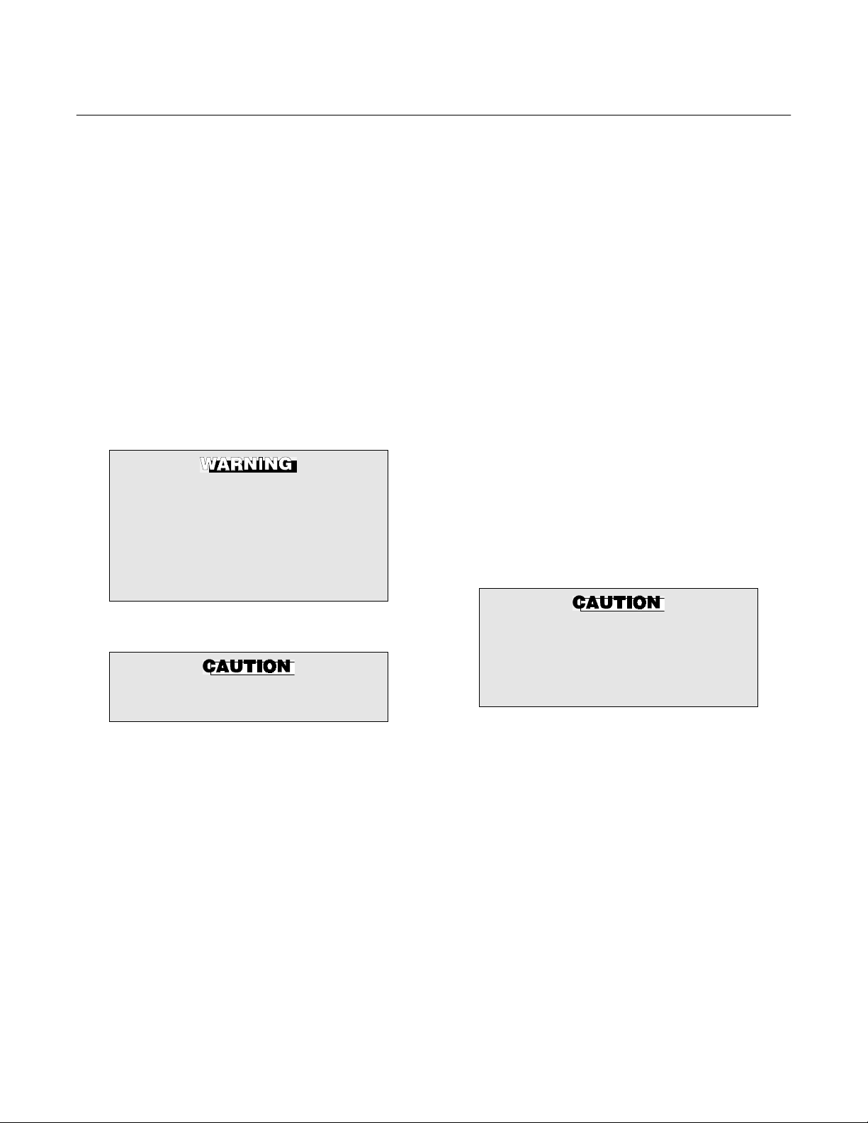
Highlights an operation or maintenance
procedure, practice, condition, statement, etc. If not strictly observed, could
result in injury, death, or long-term
health hazards of personnel.
Highlights an essential operating procedure,
condition, or statement.
: EARTH (GROUND) TERMINAL
: PROTECTIVE CONDUCTOR TERMINAL
: RISK OF ELECTRICAL SHOCK
: WARNING: REFER TO INSTRUCTION BULLETIN
NOTE TO USERS
Highlights an operation or maintenance
procedure, practice, condition, statement, etc. If not strictly observed, could
result in damage to or destruction of
equipment, or loss of effectiveness.
NOTE
The number in the lower right corner of each illustration in this publication is a manual illustration number. It is not a part number, and is not related to the illustration in any technical
manner.
Rosemount Analytical Inc. A Division of Emerson Process Management P-1

Instruction Manual
IB-106-4081 Rev. 1.2
September, 2002
FOR THE WIRING AND INSTALLATION
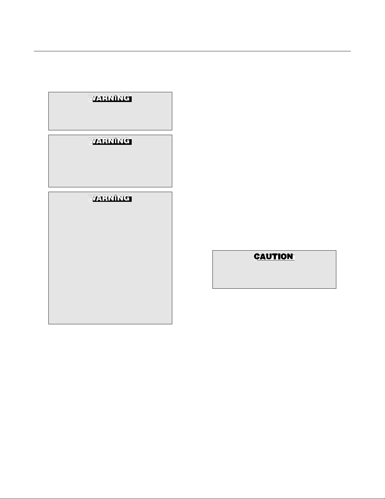
The following safety instructions apply specifically to all EU member states. They should
be strictly adhered to in order to assure compliance with the Low Voltage Directive. NonEU states should also comply with the following unless superseded by local or National
Standards.
1. Adequate earth connections should be made to all earthing points, internal and external,
where provided.
2. After installation or troubleshooting, all safety covers and safety grounds must be replaced.
The integrity of all earth terminals must be maintained at all times.
3. Mains supply cords should comply with the requirements of IEC227 or IEC245.
Model 4081FG
IMPORTANT
SAFETY INSTRUCTIONS
OF THIS APPARATUS
4. All wiring shall be suitable for use in an ambient temperature of greater than 75°C.
5. All cable glands used should be of such internal dimensions as to provide adequate cable
anchorage.
6. To ensure safe operation of this equipment, connection to the mains supply should only be
made through a circuit breaker which will disconnect all circuits carrying conductors during a
fault situation. The circuit breaker may also include a mechanically operated isolating switch.
If not, then another means of disconnecting the equipment from the supply must be provided
and clearly marked as such. Circuit breakers or switches must comply with a recognized
standard such as IEC947. All wiring must conform with any local standards.
7. Where equipment or covers are marked with the symbol to the right, hazard-
ous voltages are likely to be present beneath. These covers should only be
removed when power is removed from the equipment — and then only by
trained service personnel.
8. Where equipment or covers are marked with the symbol to the right, there is a
danger from hot surfaces beneath. These covers should only be removed by
trained service personnel when power is removed from the equipment. Certain surfaces may remain hot to the touch.
9. Where equipment or covers are marked with the symbol to the right, refer to
the Operator Manual for instructions.
10. All graphical symbols used in this product are from one or more of the follow-
ing standards: EN61010-1, IEC417, and ISO3864.
P-2 Rosemount Analytical Inc. A Division of Emerson Process Management

Model 4081FG
1
DESCRIPTION AND SPECIFICATIONS
Instruction Manual
IB-106-4081 Rev. 1.2
September, 2002
SECTION 1
1-1 COMPONENT CHECKLIST OF TYPICAL
SYSTEM (PACKAGE CONTENTS)
A typical Rosemount Two-Wire In Situ Oxygen
Analyzer should contain the items shown in
Figure 1-1. Record the part number, serial number, and order number for each component of
your system in the table located on the first
page of this manual. Also, use the product matrix in Table 1-1 to compare your order number
against your unit. The first part of the matrix defines the model. The last part defines the various options and features of the analyzer.
Ensure the features and options specified by
your order number are on or included with the
unit.
1-2 SYSTEM OVERVIEW
a. Scope
This Instruction Bulletin is designed to supply details needed to install, start up, operate, and maintain the Rosemount Two-Wire
In Situ Oxygen Analyzer. The analyzer consists of an oxygen probe and Model 4081
Transmitter. Integral signal conditioning
electronics outputs a digital F
fieldbus signal representing an O2 value. An
infrared remote control (IRC) allows access
to setup, calibration, and diagnostics. This
same information, plus additional details,
can be accessed via fieldbus digital
communications.
OUNDATION
OUNDATION
b. F
FOUNDATION fieldbus is an all digital, serial, two-way communication system that
inter-connects field equipment such as sensors, actuators, and controllers. Fieldbus is
a Local Area Network (LAN) for instruments
used in both process and manufacturing
automation with built-in capacity to distribute the control application across the network. The fieldbus environment is the base
level group of digital networks in the hierarchy of planet networks.
The fieldbus retains the desirable features
of the 4-20 mA analog system, including a
standardized physical interface to the wire,
bus powered devices on a single wire, and
intrinsic safety options, and enables additional capabilities, such as:
• Increased capabilities due to full digital
communications
• Reduced wiring and wire terminations
due to multiple devices on one set of
wires
• Increased selection of suppliers due to
inter-operability
• Reduced loading on control room
equipment with the distribution of some
control and input/output functions to field
devices
• Speed options for process control and
manufacturing applications
Fieldbus Technology
Rosemount Analytical Inc. A Division of Emerson Process Management Description and Specifications 1-1
Instruction Manual
IB-106-4081 Rev. 1.2
September, 2002
Model 4081FG
1
7
6
2
3
5
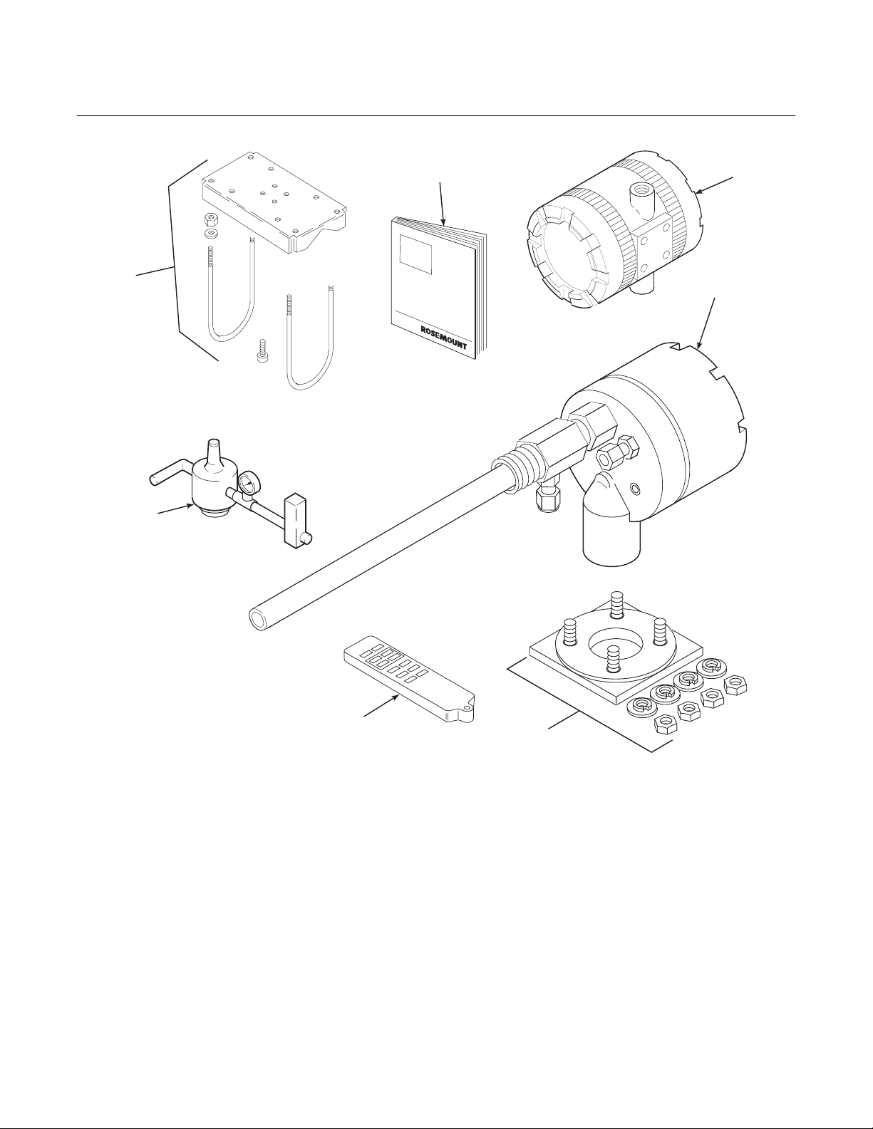
1. Instruction Bulletin
2. Model 4081 Transmitter
3. Oxygen Probe
4. Adapter Plate with Mounting Hardware
and Gasket (Optional)
5. Infrared Remote Control (IRC) (Optional)
6. Reference Air Set (Optional)
7. Pipe Mounting Kit (Optional)
4
29760001
Figure 1-1. Typical System Package
1-2 Description and Specifications Rosemount Analytical Inc. A Division of Emerson Process Management

Instruction Manual
1
IB-106-4081 Rev. 1.2
Model 4081FG
Table 1-1. Product Matrix
4081FG Model 4081FG In Situ Oxygen Analyzer with FOUNDATION Fieldbus Communications
Model 4081FG Oxygen Analyzer - Instruction Book
Code Sensing Probe Length
1 20 in. (508 mm) probe, 1/4 in. tube fittings
2 26 in. (660 mm) probe, 1/4 in. tube fittings
3 38 in. (965 mm) probe, 1/4 in. tube fittings
Code Probe Outer Tube Material - Maximum Operating Temperature
1 Alumina - 2912°F (1600°C) maximum - 1.25 NPT mounting
2 Inconel 600 - 1832°F (1000°C) maximum - 1.25 NPT mounting
Code Mounting Adapter - Stack Side
0 No adapter plate required uses 1.25 NPT (“0” must also be chosen under “Mounting Adapter” probe side)
1 New flanged installation - Square weld plate with studs (matches “Mounting Adapter” probe side)
2 Model 450 mounting (“4” must also be chosen under “Mounting Adapter” probe side)
3 Competitor's Mount (“5” must also be chosen under “Mounting Adapter” probe side)
Code Mounting Adapter - Probe Side
0 No adapter plate
1 ANSI 2 in. 150 lb flange to 1.25 NPT adapter
(6 in. dia. Flange, 4.75 in. BC with 4 x 0.75 in. dia. holes)
2 DIN to 1.25 NPT adapter (184 mm flange, 145 mm BC with 4 x 18 mm dia. holes)
3 JIS to 1.25 NPT adapter (155 mm flange, 130 mm BC with 4 x 13 mm dia. holes)
4 Model 450 to 1.25 NPT adapter
5 Competitor’s mounting flange
Code Electronics & Housing - Intrinsically Safe, NEMA 4X, IP65
1 4081 F
2 4081 F
3
4 4081 F
5 4081 F
6
4081FG2100111211 Example
OUNDATION
OUNDATION
OUNDATION
4081 F
Suite
OUNDATION
OUNDATION
4081 F
OUNDATION
Control Suite
Code Housing Mounting
0 Surface or wall mounting
1 1/2 to 2 in. pipe mounting
Fieldbus Electronics - CENELEC EEx ia IIC T5 with Control Suite
Fieldbus Electronics - CSA pending, with Control Suite
Fieldbus Electronics-FM Class I, Div. I, Groups B,C,D with Control
Fieldbus Electronics - CENELEC EEx ia IIC T5 without Control Suite
Fieldbus Electronics - CSA pending, without Control Suite
Fieldbus Electronics-FM Class I, Div. I, Groups B,C,D without
Code Communications
0 No remote control
1 Infrared Remote Control (IRC) (LCD display through cover)
Code Calibration Accessories
1 No hardware
2 Reference air flowmeters and pressure regulator
Code Armored Cable Length
00 No cable
11 20 ft (6 m)
12 40 ft (12 m)
13 60 ft (18 m)
14 80 ft (24 m)
15 100 ft (30 m)
16 150 ft (45 m)
17 200 ft (61 m)
18 300 ft (91 m)
19 400 ft (122 m)
20 500 ft (152 m)
September, 2002
Rosemount Analytical Inc. A Division of Emerson Process Management Description and Specifications 1-3

Instruction Manual
IB-106-4081 Rev. 1.2
September, 2002
Table 1-2. Accessories
Part No. Description
1A99135H01 Armored cable, bulk, uncut, no connectors 100’ minimum.
1A99135H02 Unarmored cable, bulk, uncut, no connectors 100’ minimum.
Order as separate items.
Table 1-3. Mounting Adapter
Type Description
Plate with studs Bolt circle diameter, number and arrangement of studs, stud thread, stud height
above mounting plate.
Plate without studs Bolt circle diameter, number and arrangement of holes, thread, depth of stud
mounting plate with accessories.
Where possible specify SPS number; otherwise provide details of the existing mounting plate.
Model 4081FG
c. System Description
The Rosemount Two-Wire In Situ Oxygen
Analyzer is designed to measure the net
concentration of oxygen in an industrial process; i.e., the oxygen remaining after all fuels have been oxidized. The oxygen probe
is permanently positioned within an exhaust
duct or stack and performs its task without
the use of a sampling system. The Model
4081 Transmitter is mounted remotely and
conditions the oxygen probe outputs.
The equipment measures oxygen percentage by reading the voltage developed
across an electrochemical cell, which consists of a small yttria-stabilized, zirconia
disc. Both sides of the disc are coated with
porous metal electrodes. The millivolt output
voltage of the cell is given by the following
Nernst equation:
EMF = KT log
10(P1/P2
) + C
Where:
1. P
is the partial pressure of the oxygen
2
in the measured gas on one side of the
cell.
2. P
is the partial pressure of the oxygen
1
in the reference air on the opposite side
of the cell.
3. T is the absolute temperature.
4. C is the cell constant.
5. K is an arithmetic constant.
NOTE
For best results, use clean, dry, instrument air (20.95% oxygen) as the
reference air.
NOTE
The probe uses a Type B thermocouple to measure the cell temperature.
When the cell is at 550°C to 1600°C
(1022°F to 2912°F) and there are unequal
oxygen concentrations across the cell, oxygen ions will travel from the high oxygen
partial pressure side to the low oxygen partial pressure side of the cell. The resulting
logarithmic output voltage is approximately
50 mV per decade.
The output is proportional to the inverse
logarithm of the oxygen concentration.
Therefore, the output signal increases as
the oxygen concentration of the sample gas
decreases. This characteristic enables the
Rosemount Two-Wire In Situ Oxygen Analyzer to provide exceptional sensitivity and
accuracy at low oxygen concentrations.
1-4 Description and Specifications Rosemount Analytical Inc. A Division of Emerson Process Management

Model 4081FG
1
Instruction Manual
IB-106-4081 Rev. 1.2
September, 2002
Oxygen analyzer equipment measures net
oxygen concentration in the presence of all
the products of combustion, including water
vapor. Therefore, it may be considered an
analysis on a “wet” basis. In comparison
with older methods, such as the portable
apparatus, which provides an analysis on a
“dry” gas basis, the “wet” analysis will, in
general, indicate a lower percentage of
oxygen. The difference will be proportional
to the water content of the sampled gas
stream.
d. System Configuration
The equipment discussed in this manual
consists of two major components: the oxygen probe and the Model 4081 Transmitter.
Oxygen probes are available in three length
options, providing in situ penetration appropriate to the size of the stack or duct. The
options on length are 20 in. (508 mm), 26
in. (660 mm), or 38 in. (965 mm).
The Model 4081 Transmitter is a two-wire
transmitter providing an output proportional
to the measured oxygen concentration. A
customer-supplied 24 VDC power source is
required to provide power to the electronics.
The transmitter accepts millivolt signals
generated by the probe and produces the
outputs to be used by other remotely connected devices. The output is a FOUNDATION fieldbus digital communication signal.
e. System Features
1. The cell output voltage and sensitivity
increase as the oxygen concentration
decreases.
2. High process temperatures eliminate
the need for external cell heating and
increase cell accuracy.
3. FOUNDATION fieldbus is standard.
4. Easy probe replacement due to the
lightweight, compact probe design.
5. Remote location of the Model 4081
Transmitter removes the electronics
from high temperature or corrosive
environments.
6. Power is supplied to the electronics
through the FOUNDATION fieldbus
digital signal line for intrinsic safety (IS)
purposes.
7. Infrared remote control (IRC) allows
inter-facing without exposing the
electronics.
8. An operator can operate and diagnostically troubleshoot the Two-Wire In
Situ Oxygen Analyzer in one of two
ways:
(a) Infrared Remote Control. The IRC
allows access to fault indication
menus on the Model 4081 Transmitter LCD display. Calibration can
be performed from the IRC keypad.
(b) FOUNDATION fieldbus Interface.
The transmitter’s output carries a
signal containing the oxygen level
encoded in digital format. This
digital output can also be used to
communicate with the oxygen
analyzer and access all of the oxygen analyzer status information.
9. Selected Distributed Control Systems The use of distributed control systems
requires input/output (I/O) hardware
and AMS Security codes are provided
(by infrared remote control) to prevent
unintended changes to analyzers adjacent to the one being accessed.
10. A calibration check procedure is provided to determine if the Rosemount
Two-Wire In Situ Oxygen Analyzer is
correctly measuring the net oxygen
concentration in the industrial process.
Rosemount Analytical Inc. A Division of Emerson Process Management Description and Specifications 1-5

Instruction Manual
IB-106-4081 Rev. 1.2
September, 2002
Model 4081FG
f. Handling the Analyzer
The probe was specially packaged to prevent breakage due to handling. Do not remove the padding material from the probe
until immediately before installation.
It is important that printed circuit
boards and integrated circuits are
handled only when adequate antistatic
precautions have been taken to prevent possible equipment damage.
The oxygen probe is designed for industrial applications. Treat with care
to avoid physical damage. The probe
contains components made from ceramic, which are susceptible to shock
when mishandled. THE WARRANTY
DOES NOT COVER DAMAGE FROM
MISHANDLING.
temperatures, environmental considerations, convenience, and serviceability
Figure 1-2 shows the FOUNDATION Fieldbus communications interface. A typical
system installation is illustrated in Figure
1-3.
A source of instrument air is required at the
oxygen probe for reference air use. Since
the Two-Wire In Situ Oxygen Analyzer is
equipped with an in-place calibration feature, provisions should be made for connecting calibration check gas tanks to the
oxygen probe during calibration.
If the calibration check gas bottles are to be
permanently connected, a check valve is
required next to the calibration fittings on
the integral electronics.
This check valve is to prevent breathing of
calibration check gas line and subsequent
flue gas condensation and corrosion. The
check valve is in addition to the stop valve
in the calibration check gas kit.
g. System Considerations
Prior to installing your Rosemount Two-Wire
In Situ Oxygen Analyzer, make sure you
have all the components necessary to make
the system installation. Ensure all the components are properly integrated to make the
system functional.
After verifying that you have all the components, select mounting locations and determine how each component will be placed in
terms of available line voltage, ambient
NOTE
The electronics of the Model 4081
Transmitter is rated NEMA 4X (IP65)
and is capable of operating at temperatures up to 65°C (149°F).
NOTE
Retain the packaging in which the
Rosemount Two-Wire In Situ Oxygen
Analyzer arrived from the factory in
case any components are to be
shipped to another site. This packaging has been designed to protect the
product.
1-6 Description and Specifications Rosemount Analytical Inc. A Division of Emerson Process Management

Model 4081FG
1
Instruction Manual
IB-106-4081 Rev. 1.2
September, 2002
TWO-WIRE IN SITU
OXYGEN ANALYZER
CALIBRATION CHECK
GAS LINE
Figure 1-2. Two-Wire In Situ Oxygen Analyzer Fieldbus Connections
GASES
STACK
REFERENCE
AIR LINE
OmV
2
SIGNAL
MODEL 4081
TRANSMITTER
TEMPERATURE
mV SIGNAL
DUCT
DIGITAL OUTPUT
FIELDBUS
(TWISTED PAIR)
INTRINSIC
SAFETY
BARRIER
(OPTIONAL)
FIELDBUS
COMPUTER TERMINAL
29760002
OXYGEN
PROBE
MODEL 4081
TRANSMITTER
OPTIONAL
ADAPTER
PLATE
FLOWMETER
FIELDBUS
DIGITAL SIGNAL
PRESSURE
REGULATOR
Figure 1-3. Typical System Installation
INSTRUMENT
AIR SUPPLY
(REFERENCE AIR)
29760003
Rosemount Analytical Inc. A Division of Emerson Process Management Description and Specifications 1-7

Instruction Manual
IB-106-4081 Rev. 1.2
September, 2002
1-3 SPECIFICATIONS
Net O
Range ...................................................... 0 to 25% O2 Fully Field Selectable via the FOUNDATION
2
Fieldbus Interface
Lowest Limit................................................... 0.05% O
Highest Limit.................................................. 25.00% O
2
2
Accuracy.............................................................. ±1.5% of reading or 0.05% O2, whichever is greater
System Response to Calibration Check Gas...... Initial response in less than 3 seconds
T90 in less than 10 seconds
Probe
Lengths................................................................ 20 in. (508 mm)
26 in. (660 mm)
34.625 in. (880 mm)
Temperature Limits
Process Temperature Limits ......................... 550° to 1400°C (1022° to 2552°F)
Operation to 1600°C (2912°F) with reduced cell life.
Ambient ......................................................... -40° to 149°C (-40° to 300°F) Ambient
Mounting and Mounting Position......................... Vertical or Horizontal
Materials of Construction - Process Wetted Parts
Inner Probe ............................................. Zirconia
Outer Protection Tube............................. Alumina [1600°C (2912°F) limit]
Inconel 600 [1000°C (1832°F) limit]
Probe Junction Box................................. Cast aluminum
Speed of Installation/Withdrawal......................... 1 in. (25.4 mm) per minute
Hazardous Area Certification .............................. Intrinsically safe per EN50 014 (1977), clause 1.3
(pending)
Reference Air Requirement................................. 100 ml per minute (0.2 scfh) of clean, dry instrument air;
1/4 in. tube fittings
Calibration Check Gas Fittings............................ 1/4 in. tube fittings
Cabling ................................................................ Two twisted pairs, shielded
Electronics
Enclosure ............................................................ IP65 (NEMA 4X), weatherproof, and corrosion-resistant
Materials of Construction .................................... Low copper aluminum
Ambient Temperature Limits ............................... -20° to 65°C (-4° to 149°F)
Relative Humidity ................................................ 95% with covers sealed
Inputs (from O
Probe) ........................................ Two wires - O2 signal, Two wires - type B thermocouple
2
Output ................................................................ FOUNDATION Fieldbus digital signal
Fieldbus Logic Function Blocks
Two AI Blocks: Execution Rate .................... 75mS
PID Block: Execution Rate ........................... 150mS
Fieldbus Segment Power Consumption ............. 30mA max, 30VDC max
Hazardous Area Certification .............................. Cenelec EEx ia IIC T4 or T5(2) (pending)
NEC Class I Div.I Group B,C,D (pending)
Fisher-Rosemount has satisfied all obligations coming from the
European legislation to harmonize the product requirements in Europe.
Power Transient Protection ................................. IEC 801-4
Shipping Weight .................................................. 10 lbs (4.5 kg)
Infrared Remote Control
Power Requirements........................................... Three AAA batteries
Hazardous Area Certification .............................. Cenelec EEx ia IIC Class I, Div. I, Group A, B, C, D
(1)
Thermocouple and O2 probe cell are both unpowered, developing a millivolt emf, and are considered a “simple apparatus” by certifying agencies.
(2)
Dependent on ambient temperature limits.
Model 4081FG
(1)
1-8 Description and Specifications Rosemount Analytical Inc. A Division of Emerson Process Management
Model 4081FG
2
Instruction Manual
IB-106-4081 Rev. 1.2
September, 2002
SECTION 2
INSTALLATION
2-1 PRE-INSTALLATION
a. Inspect
Carefully inspect the shipping container for
any evidence of damage. If the container is
damaged, notify the carrier immediately.
b. Packing List
Confirm all items shown on the packing list
are present. Notify Rosemount Analytical
immediately if items are missing.
Before installing this equipment, read
the “Safety instructions for the wiring
and installation of this apparatus” at
the front of this Instruction Bulletin.
Failure to follow the safety instructions could result in serious injury or
death.
2-2 MECHANICAL INSTALLATION
Avoid installation locations near
steam soot blowers.
the process gas temperature falls within
a range of 550° to 1600°C (1022° to
2912°F). Figure 2-1 provides mechanical installation references.
2. Check the flue or stack for holes and
air leakage. The presence of this condition will substantially affect the accuracy of the oxygen reading. Therefore,
either make the necessary repairs or
install the probe up-stream of any
leakage.
3. Ensure the area is clear of internal and
external obstructions that will interfere
with installation and maintenance access to the probe. Allow adequate
clearance for probe removal (Figure
2-1).
b. Installing Oxygen Probe
The probe was specially packaged to
prevent breakage due to handling. Do
not remove the padding material from
the probe until immediately before installation.
1. Ensure all components are available to
a. Locating Oxygen Probe
1. The location of the oxygen probe in the
stack or flue is important for maximum
accuracy in the oxygen analyzing process. The probe must be positioned so
the gas it measures is representative of
the process. Best results are normally
obtained if the probe is positioned near
the center of the duct (40-60% insertion).
Longer ducts may require several analyzers since the O
stratification. A point too near the wall of
the duct, or the inside radius of a bend,
may not provide a representative sample
because of the very low flow conditions.
The sensing point should be selected so
Rosemount Analytical Inc. A Division of Emerson Process Management Installation 2-1
can vary due to
2
Leave the probe inner protective cover
in place until installation. This is required to protect the ceramic cell during movement.
install the probe.
NOTE
2. If using an optional adapter plate
(Figure 2-2) or an optional mounting
flange (Figure 2-3), weld or bolt the
component onto the duct. The through
hole in the stack or duct wall and refractory material must be 2 in. (50.8
mm) diameter, minimum.

Instruction Manual
IB-106-4081 Rev. 1.2
September, 2002
Model 4081FG
Figure 2-1. Probe Installation Details
A
B
C
NOTE: DIMENSIONS ARE
IN INCHES WITH
MILLIMETERS IN
PARENTHESES.
DIMENSION
“B” THREAD 0.625-11 M-16x2 M-12x1.75
“C” DIA. 4.75 (121) 5.71 (145) 5.12 (130)
METAL WALL
STACK OR DUCT
A
WELD OR BOLT ADAPTER
PLATE TO STACK OR DUCT.
JOINT MUST BE AIR TIGHT.
PLATE DIMENSIONS
ANSI
4512C34G01
“A” 6.00 (153) 7.5 (191) 6.50 (165)
2.50 (63.5)
MIN. DIA.
JOINT MUST
BE AIR TIGHT
DIN
4512C36G01
MASONRY WALL
STACK
3.00 SCHEDULE 40
PIPE SLEEVE
SUPPLIED BY CUSTOMER
JIS
4512C35G01
WELD PIPE TO
ADAPTER PLATE
3.50 (89)
O.D. REF
29750002
Figure 2-2. Optional Adapter Plate
2-2 Installation Rosemount Analytical Inc. A Division of Emerson Process Management

Model 4081FG
2
Instruction Manual
IB-106-4081 Rev. 1.2
September, 2002
TAP 1.25 NPT
B
A
C
FLANGE DIMENSIONS
ANSI
DIMENSION
“A” DIA. 6.00 (153) 7.28 (185) 6.10 (155) 9.00 (229)
“B” DIA. 0.75 (20) 0.71 (18) 0.59 (15) 0.50 (13)
“C” DIA. 4.75 (121) 5.71 (145) 5.12 (130) 7.68 (195)
5R10158H01
DIN
5R10158H02
0.50 (12.7)
NOTE: DIMENSIONS ARE IN
INCHES WITH MILLIMETERS
IN PARENTHESES.
JIS
5R10158H03
MODEL 450
5R10158H04
29750003
Figure 2-3. Optional Probe Mounting Flange
3. If the optional adapter plates are not
used, a 2 in. NPT, schedule 40, pipe
nipple (Figure 2-4) should be welded to
the stack or duct wall.
When a 2 in. NPT to 1.25 NPT adapter
is threaded to the welded pipe nipple,
the adapter provides the pipe threads
needed for the probe’s process fitting.
Rosemount Analytical Inc. A Division of Emerson Process Management Installation 2-3

Instruction Manual
IB-106-4081 Rev. 1.2
September, 2002
Model 4081FG
STACK OR DUCT
METAL WALL
WELD PIPE TO
METAL WALL
2.0 IN. (51 mm)
MIN. DIA.
REFRACTORY
SCHEDULE 40
STACK OR DUCT
METAL WALL
ADAPTER
2 IN. NPT
PIPE
1.25 NPT
CUSTOMER
SUPPLIED
ADAPTER
INSULATE IF EXPOSED
TO AMBIENT WEATHER
CONDITIONS
2 IN. NPT
SCHEDULE 40
PIPE
CALIBRATION
CHECK
GAS LINE
REFERENCE
AIR LINE
SYSTEM
CABLE
29750004
Figure 2-4. Horizontal Probe Installation
2-4 Installation Rosemount Analytical Inc. A Division of Emerson Process Management

Model 4081FG
2
REFRACTORY
STACK OR
DUCT METAL
PROBE LENGTH
A
WAL L
1.5 + A
Instruction Manual
IB-106-4081 Rev. 1.2
September, 2002
DIMENSION A -- 1-5/8, 2-1/2, 3, OR
4 IN. 1.25 NPT SCHEDULE 40
PIPE NIPPLE
2 IN., 1.25 NPT
PIPE COUPLING
29750005
Figure 2-5. Adjusting Probe Insertion Depth
Rosemount Analytical Inc. A Division of Emerson Process Management Installation 2-5

Instruction Manual
IB-106-4081 Rev. 1.2
September, 2002
Model 4081FG
4. Where high particulate or slag is in the
flue gas stream, it may be desirable to
inset the probe in the refractory as
shown in Figure 2-5. Use pipe couplings and nipples to adjust the probe
insertion depth.
5. Use rags or other material to seal
around the probe during insertion. This
prevents hot gases from escaping or
cold air from entering the stack or duct.
6. Initially insert the probe to a depth of 3
in. (76.2 mm) or ½ the depth of the
stack or duct refractory, whichever is
greater.
After initial insertion, do not insert the
probe at a rate exceeding 1 in. per minute (25.4 mm per minute) or damage
to the probe may result due to thermal
shock.
the probe. Ensure the electrical conduit
is routed below the level of the terminal
block housing. This drip loop minimizes
the possibility that moisture will accumulate in the housing.
9. If insulation was removed to access the
duct work for probe mounting, make
sure the insulation is replaced afterward. See Figure 2-4.
If the ducts will be washed down during outage, MAKE SURE to power
down the probes and remove them
from the wash area.
c. Locating Model 4081 Transmitter
1. Ensure the Model 4081 Transmitter is
easily accessible for maintenance and
service and for using the infrared remote control (if applicable).
7. After initial insertion, insert the probe at
a rate of 1 in. (25.4 mm) per minute
until the probe is fully inserted.
8. Install anti-seize compound on the pipe
threads and screw the probe into the
process flange or adapter.
NOTE
Use anti-seize compound on threads
to ease future removal of probe.
The electrical conduit port should be
facing down for a horizontal probe installation. See Figure 2-4. In vertical
probe installations, orient the probe so
the system cable drops vertically from
Do not allow the temperature of the
Model 4081 Transmitter to exceed
65°C (149°F) or damage to the unit
may result.
2. The ambient temperature of the transmitter housing must not exceed 65°C
(149°F). Locate the electronics in an
area where temperature extremes, vibration, and electromagnetic and radio
frequency interference are minimal.
3. Locate the Model 4081 Transmitter
within 150 ft (45.7 m) of the oxygen
probe due to wiring and signal
considerations.
2-6 Installation Rosemount Analytical Inc. A Division of Emerson Process Management

Model 4081FG
2
Instruction Manual
IB-106-4081 Rev. 1.2
September, 2002
d. Installing Model 4081 Transmitter
1. Ensure all components are available to
install the Model 4081 Transmitter.
2. Choose a method or location to mount
the transmitter.
(a) Flat Surface Mounting. The trans-
mitter may be mounted on a flat
COVER
LOCK
CIRCUIT
END
6.32
(160.5)
6.35
(161.3)
TERMINAL
END
THREADED CAP
(2 PLACES)
surface using the threaded mounting holes located on the bottom of
the transmitter housing. Refer to
Figure 2-6 for installation references.
(b) Pipe Mounting. An optional pipe
mounting bracket is available for
this type of installation. Refer to
Figure 2-7 for installation
references.
TERMINAL BLOCK (TB)
TERMINAL END
CAP OMITTED
FOR CLARITY
(THIS VIEW)
1.32
(33.5)
O-RING
(2 PLACES)
NOTE: DIMENSIONS ARE IN INCHES
WITH MILLIMETERS IN
PARENTHESES.
3.68
(93.5)
Figure 2-6. Flat Surface Mounting Dimensional Information
3/4-14 NPT
(2 PLACES)
SURFACE
BY OTHERS
0.839
(21.31)
FLAT SURFACE MOUNTING
PAD HOLE PATTERN
1/4-20 THREADS
(4 PLACES)
0.839
(21.31)
26020003
Rosemount Analytical Inc. A Division of Emerson Process Management Installation 2-7

Instruction Manual
IB-106-4081 Rev. 1.2
September, 2002
6.35
(161.3)
COVER LOCK
6.9
(175.3)
Model 4081FG
TERMINAL
BLOCK (TB)
CIRCUIT
6.32
(160.5)
1.00
(25.4)
0.375 (9.525) DIA.
(4 MOUNTING
HOLES)
1.405
(35.687)
2.81
(71.374)
END
1.32
(33.5)
C
L
3.87
(98.3)
3.25
(82.55)
7.5
(190.5)
6.5
(165.1)
C
L
TERMINAL
END
3/4 -14 NPT
2 PLACES
3/4-14 FNPT
(2 PLACES)
5/16-18 NUT
4.00
(101.6)
TERMINAL END CAP
OMITTED FOR CLARITY
IN THIS VIEW.
2 IN. PIPE/WALL
MOUNTING BRACKET
(OPTION)
U-BOLT
(2 PLACES)
%
1/4-20 THREADS
BRACKET HOLE PATTERN
FOR WALL MOUNTING
NOTE:
DIMENSIONS ARE IN INCHES WITH
MILLIMETERS IN PARENTHESES.
*SCREWS FURNISHED WITH
Figure 2-7. Pipe Mounting Dimensional Information
5/16 WASHER
U-BOLT
MOUNTING KIT ONLY. NOT
FURNISHED WITH
ANALYZER/TRANSMITTER.
BOTTOM VIEW
1/4-20 SCREW*
29760016
2-8 Installation Rosemount Analytical Inc. A Division of Emerson Process Management

Model 4081FG
2
Instruction Manual
IB-106-4081 Rev. 1.2
September, 2002
3. For correct viewing orientation, the display may be changed 90 degrees, using the following procedure:
(a) Refer to Figure 2-8. Loosen the
cover lock screw until the cover
lock is disengaged from the
knurled surface on the threaded
circuit end cap.
(b) Remove the circuit end cap.
(c) Remove the three screws retaining
the display board in place.
(d) Lift and rotate the display board 90
degrees either way.
(e) Reposition the display board on
the standoffs. Install and tighten all
three screws.
(f) Install the circuit end cap and
tighten the cover lock screw to secure the cover lock in place.
CIRCUIT
END CAP
SCREW
COVER LOCK
SCREW
DISPLAY
BOARD
90
O
90
O
Figure 2-8. Display Positioning Assembly
HOUSING
29760004
Rosemount Analytical Inc. A Division of Emerson Process Management Installation 2-9
Instruction Manual
IB-106-4081 Rev. 1.2
September, 2002
Model 4081FG
2-3 ELECTRICAL INSTALLATION
All wiring must conform to local and national
codes.
Disconnect and lock out power before
connecting the unit to the power
supply.
Install all protective equipment covers
and safety ground leads after installation. Failure to install covers and
ground leads could result in serious
injury or death.
To meet the Safety Requirements of
IEC 1010 (EC requirement), and ensure
safe operation of this equipment, connection to the main electrical power
supply must be made through a circuit
breaker (min 10 A) which will disconnect all current-carrying conductors
during a fault situation. This circuit
breaker should also include a mechanically operated isolating switch. If
not, then another external means of
disconnecting the supply from the
equipment should be located close by.
Circuit breakers or switches must
comply with a recognized standard
such as IEC 947.
a. General
The power supply and signal wiring should
be shielded. Also, make sure the signal
wiring is grounded at the Model 4081
Transmitter end only. Do not ground the
signal loop at more than one point. Twisted
pairs are recommended. Ground the transmitter housing to an earth ground to prevent
unwanted electromagnetic interference
(EMI) or radio frequency interference (RFI).
NOTE
For optimum EMI/RFI immunity, shield
the FOUNDATION fieldbus signal cable and enclose in an earth grounded
metal conduit.
Never run signal or sensor wiring in
the same conduit, or open tray, with
power cables. Keep signal or sensor
wiring at least 12 in. (0.3 m) away from
other electrical equipment and 6.5 ft (2
m) from heavy electrical equipment.
It is necessary to prevent moisture from
entering the Model 4081 Transmitter housing. The use of weather-tight cable glands is
required. If conduit is used, plug and seal
connections on the transmitter housing to
prevent moisture accumulation in the terminal side of the housing.
Moisture accumulation in the transmitter housing can affect its performance
and may void its warranty.
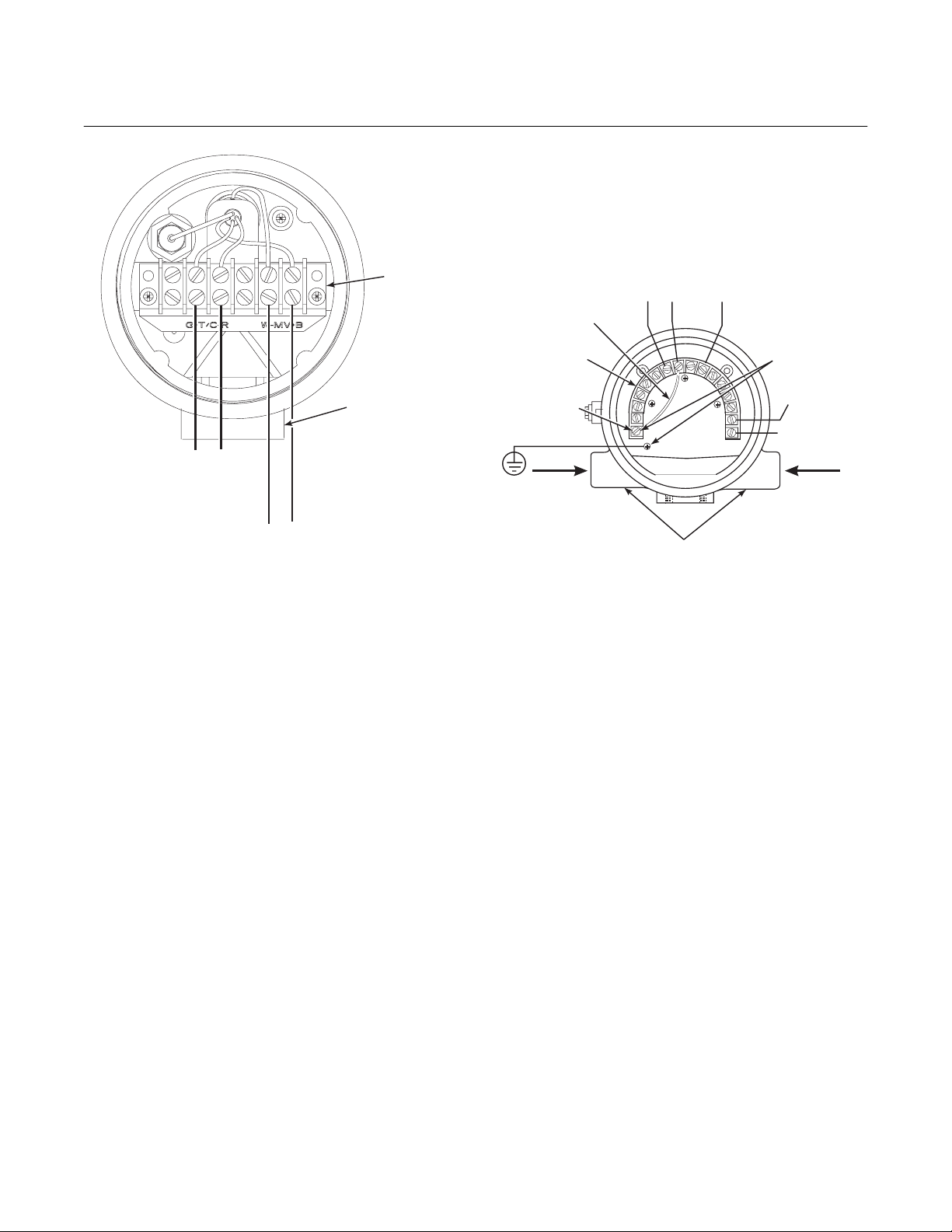
b. Oxygen Probe Signal Connections
1. Two signals represent the O
and the cell temperature. The probe
provides these values to the Model
4081 Transmitter for processing and
signal conditioning.
2. Wiring connections for the probe are
shown in Figure 2-9.
value
2
2-10 Installation Rosemount Analytical Inc. A Division of Emerson Process Management
Model 4081FG
2
TERMINAL
BLOCK
CONDUIT
FACTORY-INSTALLED
JUMPER
TERMINAL
BLOCK (TB1)
PROBE
CABLE
SHIELD
GROUND
4
3
12
Instruction Manual
IB-106-4081 Rev. 1.2
September, 2002
CELL - (WH)
THERMOCOUPLE - (RD)
CELL + (BK)
7
6
5
THERMOCOUPLE + (GY)
EARTH
GROUND
11
12
TERMINALS
FIELDBUS
13
DIGITAL (-)
14
15
FIELDBUS
16
DIGITAL (+)
8
9
10
THERMOCOUPLE + (GY)
THERMOCOUPLE - (RD)
CELL - (WH)
CELL + (BK)
26020004
Figure 2-9. Oxygen Probe Terminal Block
c. Model 4081 Transmitter and F
OUNDATION
Fieldbus Signal Connections
1. Two signals representing the O
value
2
and the cell temperature are supplied
to the Model 4081 Transmitter from the
oxygen probe.
2. Wiring connections for the Model 4081
Transmitter are shown in Figure 2-10.
NOTE
The ground arrangement shown in
Figure 2-10 limits the amount of noise
introduced into the electronics.
3. Connect wire shields to terminal 1.
Connect earth ground as shown.
CELL AND
THERMOCOUPLE
CONDUITS
NOTE:
RUN CELL AND THERMOCOUPLE SIGNALS IN
SEPARATE CONDUIT FROM .FIELDBUS
Figure 2-10. Model 4081 Transmitter
Terminal Block
2-4 PNEUMATIC INSTALLATION
a. General
Reference air is required for O
and calibration check gas is required during
a calibration check. Refer to Figure 2-11 for
the gas connections on the oxygen probe.
b. Reference Air Package
After the oxygen probe is installed, connect
the reference air set. Install the reference
air set according to Figure 2-12.
c. Instrument Air (Reference Air)
Instrument air is required for reference. Use
10 psig (68.95 kPa gage) minimum,
FIELDBUS
DIGITAL
29760005
calculation,
2
Rosemount Analytical Inc. A Division of Emerson Process Management Installation 2-11

Instruction Manual
IB-106-4081 Rev. 1.2
September, 2002
225 psig (1551.38 kPa gage) at 0.2 scfh
(100 ml/min.); less than 40 parts-per-million
total hydrocarbons. Regulator outlet pressure should be set at 5 psi (35 kPa).
d. Calibration Check Gas
Two calibration check gas concentrations
are used with the Two-Wire In Situ Oxygen
Analyzer: Low Gas - 0.4% O
- 8% O
Do not use 100% nitrogen. See Figure 2-11
for the probe connections. Set both calibration check gases at the same flow rate:
5 scfh (2.5 L/min).
, each with the balance in nitrogen.
2
and High Gas
2
Model 4081FG
1/4 TUBE FITTING
(REFERENCE AIR PORT)
1/4 TUBE FITTING
(CALIBRATION CHECK
Figure 2-11. Oxygen Probe Gas Connections
GAS PORT)
REFERENCE
AIR VENT
26020006
4.81 (122.17)
FLOW SET
POINT KNOB
0.125-27 NPT FEMALE
OUTLET CONNECTION
1
2
1.19
(30.22)
DRAIN VALVE
OUTLET
10.0
(254)
REF
3.12 (79.25) MAX
3
(SUPPLIED BY CUSTOMER)
1/4” TUBE
2.250 (57.15)
2.0
(50.80)
1.50
(38.10)
1 FLOWMETER 0.2-2.0 SCFH 771B635H08
2 2" PRESSURE GAGE 0-15 PSIG 275431-006
3 COMBINATION FILTER-REG. 0-30 PSIG 4505C21G01
TO PROBE
NOTE: DIMENSIONS ARE IN INCHES WITH
0.25-18 NPT FEMALE
INLET CONNECTION
2 MOUNTING HOLES
3.19 (81.03) LG
THROUGH BODY FOR
0.312 (7.92) DIA BOLTS
REF AIR SET
263C152G05
MILLIMETERS IN PARENTHESES.
8.50
(215.90)
MAX
INSTRUMENT
AIR SUPPLY
10-225 PSIG
MAX PRESSURE
SCHEMATIC HOOKUP FOR REFERENCE AIR SUPPLY ON OXYGEN PROBE.
26020034
Figure 2-12. Air Set, Plant Air Connection
2-12 Installation Rosemount Analytical Inc. A Division of Emerson Process Management
Loading...