

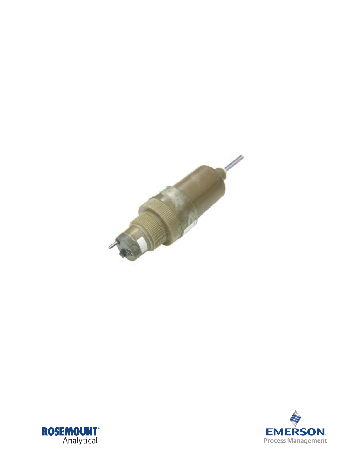
381+ Rebuildable
pH Sensor
Instruction Manual
LIQ_MAN_381+
January 2013

81+ pH Sensor Instruction Manual
3
January 2013 LIQ_MAN_381+
This page left blank intentionally

Essential Instructions
Read this page before proceeding
Emerson Process Management designs, manufactures and tests its products to meet many national
and international standards. Because these sensors are sophisticated technical products, you MUST
properly install, use, and maintain them to ensure they continue to operate within their normal spec-
fications. The following instructions MUST be adhered to and integrated into your safety program
i
when installing, using, and maintaining Rosemount Analytical products. Failure to follow the proper
instructions may cause any one of the following situations to occur: Loss of life; personal injury; property damage; damage to this sensor; and warranty invalidation.
• Read all instructions prior to installing, operating, and servicing the product.
• If you do not understand any of the instructions, contact your Emerson Process Management
representative for clarification.
• Follow all warnings, cautions, and instructions marked on and supplied with the product.
• Inform and educate your personnel in the proper installation, operation, and maintenance of the
product.
• Install your equipment as specified in the Installation Instructions of the appropriate Instruction
Manual and per applicable local and national codes. Connect all products to the proper electrical
and pressure sources.
• To ensure proper performance, use qualified personnel to install, operate, update, program, and
maintain the product.
• When replacement parts are required, ensure that qualified people use replacement parts specified by Emerson Process Management. Unauthorized parts and procedures can affect the
product's performance, place the safe operation of your process at risk, and VOID YOUR
WARRANTY. Look-alike substitutions may result in fire, electrical hazards, or improper operation.
• Ensure that all equipment doors are closed and protective covers are in place, except when
maintenance is being performed by qualified persons, to prevent electrical shock and personal
injury.
The information contained in this document is subject to change without notice.
DANGER: HAZARDOUS AREA INSTALLATION
Installations near flammable liquids or in hazardous area locations must be carefully evaluated by
qualified on site safety personnel. This sensor is not Intrinsically Safe or Explosion Proof.
To secure and maintain an intrinsically safe installation, the certified safety barrier, transmitter, and
sensor combination must be used. The installation system must comply with the governing approval
agency (FM, CSA or BASEEFA/CENELEC) hazardous area classification requirements. Consult your
analyzer/transmitter instruction manual for details.
Proper installation, operation and servicing of this sensor in a Hazardous Area Installation is entirely
the responsibility of the user.
CAUTION: SENSOR/PROCESS APPLICATION COMPATIBILITY
The wetted sensor materials may not be compatible with process composition and operating conditions. Application compatibility is entirely the responsibility of the user.
Essential Instructions I

bout This Document 381+ pH Sensor Instruction Manual
A
January 2013 LIQ_MAN_381+
About this document
This manual contains instructions for installation and operation of the 381+ High Performance
pH/ORP Sensor. The following list provides notes concerning all revisions of this document.
Rev. Level Date Notes
0 5/01 This is the initial release of the product manual. The manual
has been reformatted to reflect the Emerson documentation
style and updated to reflect any changes in the product offering.
A 6/02 Updated multiple drawings throughout.
B 7/02 Added 1055 wiring drawing and updated kPa references.
C 9/02 Revised drawing captions on page 9.
D 9/04 Add Xmt wiring drawings and delete Ultrasonic cleaner.
E 11/07 Added M certs on back page.
G 3/12 Update addresses - mail and web
H 1/2013 Update document format per new guidelines. Update of product
information.
II Table of Contents

81+ pH Sensor Instruction Manual Table of Contents
3
LIQ_MAN_381+ January 2013
Contents
Section 1: Description and Specifications
1.1 Features and Applications ............................................................................................1
1.2 Specifications ...............................................................................................................2
1.3 Ordering Information ...................................................................................................2
Section 2: Installation
2.1 Installation....................................................................................................................5
2.2 Submerssion Installation..............................................................................................5
2.3 Insertion Installation.....................................................................................................6
2.4 Flow-Through Installation.............................................................................................6
2.5 Flow Powered Cleaner Installation................................................................................9
2.6 Wiring...........................................................................................................................9
Section 3: Start-Up and Operation
3.1 Start-Up .....................................................................................................................19
3.2 pH Calibration ............................................................................................................19
3.3 ORP Standardization ..................................................................................................19
Section 4: Maintenance
4.1 General.......................................................................................................................21
4.2 Sensor Removal..........................................................................................................21
4.3 Monthly Maintenance ................................................................................................21
4.4 Annual Maintenance...................................................................................................22
4.5 Electrode Checking and Standardi zation....................................................................22
Section 5: Troubleshooting
5.1 Sensor Troubleshooting .............................................................................................23
5.2 T. C. Element Evaluation .............................................................................................24
Section 6: Return of Materials
6.1 General.......................................................................................................................25
6.2 Warranty Repair .........................................................................................................25
6.3 Non-Warranty Repair .................................................................................................25
Table of Contents III

able of Contents 381+ pH Sensor Instruction Manual
T
January 2013 LIQ_MAN_381+
IV

81+ pH Sensor Instruction Manual Section 1: Description and Specifications
3
LIQ_MAN_381+ January 2013
Section 1: Description and Specifications
1.1 Features and Applications
The Rosemount Analytical 381+ Sensor measures the pH or the Oxidation Reduction Potential
(ORP) of aqueous solutions in pipelines, open tanks or ponds. The sensor is used in most indus trial applications including water and waste treatment plants.
The 381+pH Sensor features continuous on-line advanced diagnostics that allow the user to
identify sensor failures such as coated reference junction or broken glass. Sensor diagnostics
result in time and money savings by reducing the guesswork in sensor maintenance and
replacement requirements. On-line sensor diagnostics are made possible by calculation of the
temperature corrected glass electrode impedance and by characterizing failure modes.
The sensor is housed in a molded PES body and has two O-ring seals with breach lock threads
which secure the PES cover. This provides a waterproof union for long operating life and easy
removal for routine maintenance.
The modular body design eliminates the need for internal mounting brackets, terminal brackets
and screws. All components are screw-type or plug-in-place, allowing for fast simple service.
The integral preamplifier conditions the high impedance glass elec trode signal at the sensor. The
Rosemount Analytical method of preampli fication has become the industry standard for reliable
pH measurement. In submersion applications at temperatures greater than 80°C, the preamplifier must be located in a remote junction box or in the instrument.
A double junction, gel-filled reference cell, a standard feature of the 381+, improves sensor life
when unknown reference cell contaminants, such as sulfides, may exist. The gel solution maintains its viscosity at high temperatures, and resists the effect of pumping and dilution, resulting
in an extended service life. A choice of wood or ceramic liquid junction allows the user to optimize performance by emphasizing reference lifetime (wood) or chemical resistance (ceramic).
In flow applications where crystalline or viscous coatings, such as calcium carbonate or
petroleum oils, may coat the electrode surfaces and impede the sensor’s performance, the flowpowered cleaning option may be used. A specially designed flow chamber directs the process
fluid in a circular path carrying four Teflon balls which clean the electrode surface, physically
preventing accumulation of coating materials. Flow-powered cleaning is suitable for all
hazardous area applications.
The 381+ comes with Pt100 temperature compensation and is compatible with the 54e, 56,
1055, 1056 and 1057 Analyzers, and 81, 1066, 3081, 4081, 5081-P, 6081, and Xmt-P pH/ORP
Transmitters.
Description and Specifications 1

ection 1: Description and Specifications 381+ pH Sensor Instruction Manual
S
January 2013 LIQ_MAN_381+
1.2 Specifications
Materials of Construction:
Body, Cover and Flow Cell: Polyethersulfone (PES)
O-Rings: Viton
Measuring Electrode: Glass (and platinum or gold for ORP)
Liquid Junction: Kynar/wood (Code 20) or Kynar/ceramic (Code 21)
Solution Ground: 316 Stainless steel
Sensor Process Connections:
Submersion: 3/4 in. MNPT
Insertion: 2 in. MNPT
Flow Through Cell: 3/4 in. MNPT inlet and outlet
Measuring Ranges:
ORP; -1500 to +1500 mV
pH; AccuGlass 0-14
Minimum Conductivity: 75 mS/cm
Temperature Compensation: Automatic, 0 to 100°C (32 to 212°F)
Maximum Pressure/Temperature Rating:
790 kPa (abs) at 100°C (100 psig at 212°F)
Cable: 10 conductor, shielded cable
Weight/Shipping Weight: 1.0 kg/1.7 kg (2.2 lb/3.7lb)
1.3 Ordering Information
The 381+ pH/ORP Sensor is housed in a PES body suitable for insertion, submersion or flow
through installation. The sensor includes an integral preamplifier, measuring electrode, double
junction gel filled reference cell, automatic temperature compensation, and a choice of two
cable lengths, 15 ft. or 50 ft. (4.5 or 15.2 m). The 381+ sensor provides on line advanced diagnostic capabilities and is compatible with the 54e pH/ORP and 56, 1055, 1056, and 1057
Analyzers and 81, 3081, 4081, 5081, and Xmt pH/ORP Two-Wire Transmitters, as well as 6081
Wireless Transmitters.
2 Description and Specifications

381+ pH Sensor Instruction Manual Section 1: Description and Specifications
LIQ_MAN_381+ January 2013
381+ INSERTION, SUBMERSION, FLOW THROUGH SENSOR
Level 0 FUNCTION
+ pH or ORP assembly for 54, 54e, 56, 1055, 1056, 1057, 1066, 81, 3081, 4081, 5081-P, Xmt-P and 6081
Level 1 TEMPERATURE COMPENSATOR
1 Automatic TC, 100 ohm RTD
3
Level 2 CABLE
40 15 ft (4.5 m) cable for integral sensor preamp (use option 55)
41
43 50 ft (15.2 m) cable for integral sensor preamp (use option 55)
Level 3 MEASURING ELECTRODE
10 General purpose pH, GPHT (0-14)
11
12 Ruggedized pH Electrode. For abrasive solutions
13 Platinum ORP Electrode
14 Gold ORP Electrode
15 HF pH Electrode. For HF concentrations less than 300 ppm
15 ft (4.5 m) coax cable w/BNC connector for remote sensor preamp and integral analyzer preamp (use option 52)
High pH Electrode, requires Code 21. For sodium concentrations greater than 1pH or continuous measurement
above 11 pH
Level 4 LIQUID JUNCTION
20 Wood/Kynar Liquid Junction
21 Ceramic/Kynar Liquid Junction
Level 5 PREAMPLIFIER
52 Preamp NOT REQUIRED (use option 41)
55 Preamp for 54/e, 56, 81, 1055, 1056, 1057, 1066, 3081, 4081, 5081-P, 6081 and Xmt-P
Level 6 INSTALLATION
- No Selection
02 Submersion
03 Flow Through
04 Flow Through with Flow Powered Cleaner
Level 7 SPECIAL
- No Selection
99 Special (consult factory)
Description and Specifications 3

ection 1: Description and Specifications 381+ pH Sensor Instruction Manual
S
January 2013 LIQ_MAN_381+
ACCESSORIES
PART # DESCRIPTION
23550-00
23555-00
23557-00 Preamplifier for junction box, (54/e,
9210012 Buffer Solution, pH 4.01, 16 oz.
9210013 Buffer Solution, pH 6.86, 16 oz.
9210014 Buffer Solution, pH 9.18, 16 oz.
Junction Box, with extension board for point-to-point wiring
Remote junction box with preamp (for 54/e, 56, 81, 3081, 4081, 1056, 1057. 1066, 5081-P, 6081, and Xmt-P compatible)
56, 81, 1056, 1057. 1066,
3081, 4081, 5081-P, 6081, and Xmt-P compatible)
SPARE PARTS
PART # DESCRIPTION
2000734 Liquid Junction, KYNAR/wood
2000735 Liquid Junction, KYNAR/Ceramic
22694-00 Electrode, pH, GP
22694-01 Electrode, High pH
22694-02 Electrode,pH, Rugged
22694-03 Electrode, pH, HF Resistant
22697-00 Electrode, Combination pH
22697-01 Electrode, HIgh pH, Combination
22723-00 Flow Powered Cleaner Balls (quantity 9)
22731-00 ORP Electrode, Platinum
22751-00 O-ring Kit (quantity 5) with O-ring PN 9550141
22751-01 O-ring Kit (quanity 5) with O-ring PN 9550128
22811-01 Flow Powered Cleaner - Retrofit Kit, code -00, -02
22892-00 Flow powered cleaner retrofit kit (for use with Option -03 sensors)
23018-00 Reference element (formerly 22688-00)
23551-00 Sensor Body, complete, Pt-100
23552-00 Sensor Cover with 15’ Cable
23552-01 Sensor Cover with 15’ Coax Cable
23552-02 Sensor Cover with 50’ Cable
32602-00 Flow Cell, PES
32605-00 Electrode, Shroud, Protective
32606-00 Flow Cell Coupling Nut, PES
32793-00 Flow Powered Cleaner, Ring
32794-00 Flow Powered Cleaner Chamber
9210342 Reference Cell Recharge, KCl gel, 250 ml
9550146 Viton O-Ring for Shroud
9550147 Viton O-Ring for Flow Cell
23561-00 Plug-in Preamplifier
4 Description and Specifications

81+ pH Sensor Instruction Manual Section 2: Installation
3
LIQ_MAN_381+ January 2013
Section 2: Installation
2.1 Installation
Prepare the sensor for instal la tion as follows (see Figure 2-1):
1. Remove the cover from the body by grasping the body and rotating the cover 1/4-turn
counter clockwise.
2. When the cover breaks loose from the body, pull the cover straight out.
3. Lubricate the seals of the glass electrode with O-ring lubricant and install the glass electrode
in the body. Tighten the electrode nut by hand. DO NOT use tools.
CAUTION
Do not get lubricant on tip of glass or metal electrode. It will disrupt the electrical circuit path.
4. Make sure the double junction electrode is threaded tightly.
5. Plug the preamplifier (or remote connector) onto the T.C. solution ground and microjunction reference electrode pins.
6. Connect the BNC connector from the glass elec trode to the preamplifier (or remote
connector).
7. Install the body O-rings. Make sure they are clean, and not twisted. Make sure the covers
mating surface faces are clean.
8. Lubricate the body O-rings with O-ring lubricant.
9. Plug the cable connector to the preamplifier, making sure the cable is toward the center of
the body.
10. Install the cover on the body so that the threads will engage.
11. Rotate the cover until the triangle on the body aligns with (or falls within) the adjacent mark
on the cover.
12. While holding the sensor in an upright position (see Figure 2-1), remove the 1/4-inch shipping plug from the electrode tip end of the sensor.
13. Install the liquid junction in place of the 1/4-inch plug, using TEFLON tape on the liquid junction threads.
CAUTION
DO NOT use pipe joint compound or pipe dope on the threads of the liquid junction. The electrical
circuit will be disrupted if the liquid junction is contaminated.
2.2 Submersion Installation (code 02)
To install the sensor in process proceed as follows (see Figure 2-2):
1. Wrap TEFLON tape on 3/4-inch MNPT threads of cover and on standpipe threads.
CAUTION
Do not use a pipe wrench on the plastic parts. Severe damage could result.
Installation 5
 Loading...