

Model 1181 pH/ORP
Combination pH/ORP Two-Wire Transmitters
Instruction Manual
PN 51-1181pH/rev.B
March 2003

DANGER
HAZARDOUS AREA INSTALLATION
INTRINSICALLY SAFE INSTALLA
TION
Transmitter/Sensor is not Intrinsically safe.
Installations in hazardous area locations must be
carefully evaluated by qualified on site safety personnel. To secure and maintain an intrinsically safe
installation, an appropriate safety barrier must be
used and the installation must be performed in
accordance with the governing approval agency
(FM, CSA or BASEEFA/ CENELEC) installation
drawing requirements (see Section 2.0-Installation).
EXPLOSION-PROOF INSTALLATION
Sensors are not explosion-proof and must be
installed in a non-hazardous location. If the sensor
must be installed in a hazardous location an intrinsically safe system must be implemented. To maintain the explosion-proof rating of the transmitter,
the following conditions must be met:
• Discontinue power supply before removing
enclosure covers.
• Transmitter covers must be properly installed
during power on operation.
• Explosion proof "Y" fittings must be properly
installed with sealing compound prior to applying
power to the transmitter.
• Serial tag cover over the external Zero and Span
adjustments must be in place.
• See Installation Section for details.
Proper installation, operation and servicing of this
instrument in a Hazardous Area Installation is
entirely the responsibility of the user.
ESSENTIAL INSTRUCTIONS
READ THIS PAGE BEFORE PROCEEDING!
Rosemount Analytical designs, manufactures, and tests its products to
meet many national and international standards. Because these instruments are sophisticated technical products, you must properly install,
use, and maintain them to ensure they continue to operate within their
normal specifications. The following instructions must be adhered to
and integrated into your safety program when installing, using, and
maintaining Rosemount Analytical products. Failure to follow the proper instructions may cause any one of the following situations to occur:
Loss of life; personal injury; property damage; damage to this instrument; and warranty invalidation.
• Read all instructions prior to installing, operating, and servicing the
product. If this Instruction Manual is not the correct manual, telephone 1-800-654-7768 and the requested manual will be provided.
Save this Instruction Manual for future reference.
• If you do not understand any of the instructions, contact your
Rosemount representative for clarification.
• Follow all warnings, cautions, and instructions marked on and supplied with the product.
• Inform and educate your personnel in the proper installation, operation, and maintenance of the product.
• Install your equipment as specified in the Installation Instructions of
the appropriate Instruction Manual and per applicable local and
national codes. Connect all products to the proper electrical and
pressure sources.
• To ensure proper performance, use qualified personnel to install,
operate, update, program, and maintain the product.
• When replacement parts are required, ensure that qualified people
use replacement parts specified by Rosemount. Unauthorized parts
and procedures can affect the product’s performance and place the
safe operation of your process at risk. Look alike substitutions may
result in fire, electrical hazards, or improper operation.
• Ensure that all equipment doors are closed and protective covers
are in place, except when maintenance is being performed by qualified persons, to prevent electrical shock and personal injury.
Emerson Process Management
Rosemount Analytical Inc.
2400 Barranca Parkway
Irvine, CA 92606 USA
Tel: (949) 757-8500
Fax: (949) 474-7250
http://www.raihome.com
© Rosemount Analytical Inc. 2003
About This Document
This manual contains instructions for installation and operation of the Model 1181 pH/ORP Two-wire
transmitter. The following list provides notes concerning all revisions of this document.
Rev. Level Date Notes
A 7/01 This is the initial release of the product manual. The manual has been reformatted to
reflect the Emerson documentation style and updated to reflect any changes in the
product offering and agency certification.
B 3/03 Updated CE information.
i
MODEL 1181 pH/ORP QUICK START-UP
QUICK START-UP
I. Set up
1. For non-hazardous areas or bench testing, set-up
the transmitter & sensor as illustrated in Figure A.
2. For hazardous or intrinsically safe installations,
set-up the transmitter & sensor as illustrated in the
appropriate agency drawing (Figure 2-5 through 2-
12).
The 1181pH two-wire transmitter is factory configured
to work, right out of the box, for many applications.
Factory Settings:
• 0-14pH measurement range: 0pH (low range) corresponds to 4mA output; 14pH (high range) corresponds to 20mA output.
• Automatic temperature compensation is utilized.
• (Optional LCD is set for 0-100% read out) If these
settings are acceptable to your process you can
utilize this quick start up procedure.
FIGURE A
DWG. NO. REV.
40118153 B
TB2

ii
MODEL 1181 pH/ORP QUICK START-UP
7. Repeat Step 2 through 7 until no further adjustments are required. Rinse the sensor in clean
water prior to placing it in a different buffer solution.
8. Remove DVM and connect power supply end
directly to the transmitter.
III. Standardize to the Process
A slight adjustment of the 1181 ZERO pot may be necessary to fine tune the loop to your process.
1. Install sensor into it’s final mounting position, and
allow sensor to acclimate to the process temp.
(Wait for reading to stabilize).
2. Take a grab sample of the process, close to the
sensor, and have it analyzed. Note the pH value.
3. Adjust the 1181 ZERO control (under serial label)
until the display reads the percentages of full-scale
that corresponds to the grab sample pH value.
Grab Sample pH
14 pH
X 100 = % of full scale
6.86
14 pH
X 100 = 49.0 %
4. Start-up and calibration is now complete. Refer to
1181pH manual for further details on 1181 features.
II. Solution Calibration
1. Obtain two buffer solutions. One should represent
a low range, and the other a high range value.
Typical buffer solution values 4pH, 7 pH & 10 pH.
2. Place the sensor in the lower range buffer solution, allow the reading to stabilize.
3. a. adjust ZERO control (under the serial label)
until the DVM reads the current output value
that corresponds to the buffer value.
Buffer value-Low pH range
mA =
___________________________
x 16 mA + 4
mA
High pH range-Low pH range
Example: For 4 pH buffer solution;
Range of 0-14 pH
4 pH-0 pH
Ex.=
__________
x 16 mA + 4 mA= 8.57 mA
14 pH-0 pH
b. If a liquid crystal display is installed, adjust the
LCD ZERO pot (on LCD face) until the display
indicates the proper percentage of full scale
value.
Buffer pH value
% Reading =
______________
x 16 mA + 4 mA
High pH range
4 pH
Ex.=
______
x 100 = 28.6%
14 pH
4. Remove the sensor from the low range buffer, and
rinse it in clean water.
5. Place the sensor in high range buffer, and allow
the reading to stabilize.
6. a. adjust the SPAN control (under serial label) until
DVM reads the current output value that corresponds to the computed buffer value.
10 pH-0 pH
Ex.=
__________
x 16 mA + 4 mA= 15.43 mA
14 pH-0 pH
b. If a LCD is installed, adjust the LCD SPAN pot
(on LCD face), until the display indicates the
proper percentage of the computed full-scale
value.
10 pH
Ex.=
______
x 100 = 71.4%
14 pH

MODEL 1181 pH/ORP TABLE OF CONTENTS
MODEL 1181pH/ORP
TWO-WIRE TRANSMITTERS
TABLE OF CONTENTS
Section Title Page
1.0 DESCRIPTION AND SPECIFICATIONS .......................................................... 1
1.1 Features and Applications................................................................................. 1
1.2 Performance Specifications - General .............................................................. 2
1.3 Physical Specifications - General...................................................................... 3
1.4 Model 1181pH Transmitter ................................................................................ 3
1.5 Model 1181ORP Transmitter............................................................................. 3
1.6 Ordering Information ......................................................................................... 4
2.0 INSTALLATION ................................................................................................. 5
2.1 General ............................................................................................................. 5
2.2 Mechanical Installation ..................................................................................... 5
2.3 Electrical Installation ........................................................................................ 6
2.4 Hazardous Locations-Explosion Proof Installations ......................................... 7
2.5 Hazardous Locations-lntrinsically Safe Installations ........................................ 7
3.0 START-UP AND CALIBRATION ...................................................................... 18
3.1 Start-Up............................................................................................................. 18
3.2 ModeI 1181/ORP pH Start-Up .......................................................................... 18
3.3 System Calibration ........................................................................................... 21
3.4 Operation With A Fixed T.C............................................................................... 22
3.5 ModeI 1181 pH Start-Up ................................................................................. 22
3.6 Model 1181ORP System Calibration ................................................................ 24
3.7 Operating With Integral Preamp (Accessory) ................................................... 25
3.8 Start-Up ............................................................................................................ 26
3.9 Test Equipment ................................................................................................. 26
3.10 Set-Up ............................................................................................................... 26
3.11 Calibration ......................................................................................................... 28
3.12 End Test ........................................................................................................... 28
3.13 Start-Up............................................................................................................. 28
3.14 LCD: Module Only ............................................................................................ 28
4.0 THEORY OF OPERATION .............................................................................. 31
4.1 Function Description ........................................................................................ 31
5.0 MAINTENANCE AND TROUBLESHOOTING ................................................. 32
5.1 General ............................................................................................................. 32
5.2 Troubleshooting ................................................................................................ 32
5.3 Maintenance...................................................................................................... 32
6.0 PARTS LIST ..................................................................................................... 38
6.1 General ............................................................................................................. 38
7.0 RETURN OF MATERIAL................................................................................... 44
iii

MODEL 1181 pH/ORP TABLE OF CONTENTS
LIST OF FIGURES
Figure Title Page
1-1 Blind & Analog Display Load/Power Supply Requirements .............................. 2
1-2 Digital Display Load/Power Supply Requirements............................................ 2
2-1 Transmitter Mounting Details ............................................................................ 5
2-2 Transmitter Wiring Detail................................................................................... 6
2-3 Integral Preamp Installation .............................................................................. 8
2-4 Wiring Details Integral Preamp ......................................................................... 9
2-5
Installation of 1181 Series for Intrinsically Safe Operation (CENELEC)
................. 10
2-6
Installation of 1181 Series for Intrinsically Safe Operation (CENELEC)
................. 11
2-7
Installation of 1181 Series for Intrinsically Safe Operation (CENELEC)
................. 12
2-8 Schematic, System 1181 pH & ORP, CSA........................................................ 13
2-9 Schematic, System F.M. I.S. Approved-Entity................................................... 14
2-10 Schematic, System F.M. I.S. Approved-Entity................................................... 15
2-11 Schematic, System F.M. I.S. Approved-Entity................................................... 16
2-12 Schematic, System F.M. E.P. Approved............................................................ 17
3-1 Location of Controls .......................................................................................... 19
3-2 pH Range Selection Switches........................................................................... 20
3-3 ORP Range Selection Switches........................................................................ 23
3-4 ORP Test Setup ................................................................................................ 24
3-5 Test Wiring ........................................................................................................ 26
3-6 LCD Calibration................................................................................................. 27
3-7 LCD Test Setup Wiring ...................................................................................... 29
3-8A PCB Layout Transmitter Board P/N 22795-02 .................................................. 30
3-8B PCB Layout Transmitter Board P/N 22795-01 .................................................. 30
4-1 Simplified Block Diagram .................................................................................. 31
5-1 Model 1181 pH/ORP Schematic Diagram ......................................................... 34
5-2 Model 1181 pH/ORP Schematic Diagram — FM Intrinsically Safe ................... 35
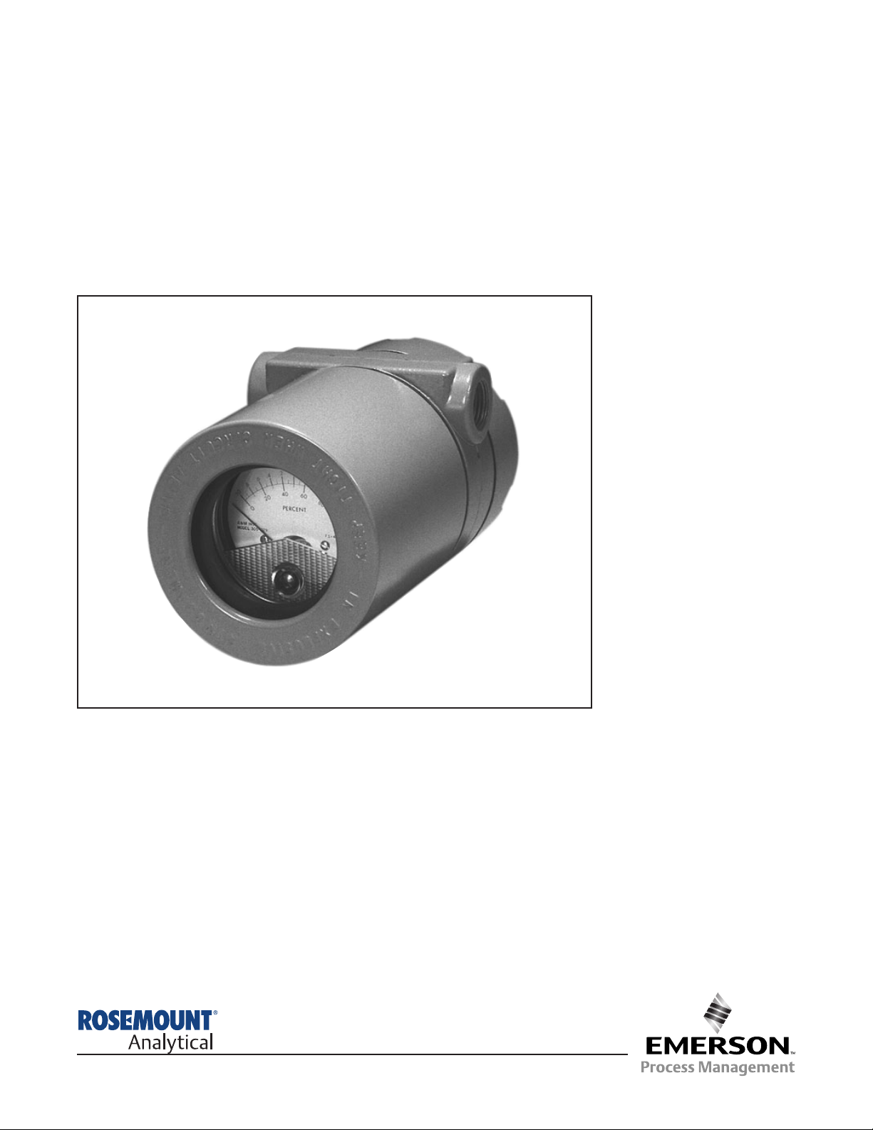
6-1 Model 1181 pH/ORP Two-Wire Transmitters .................................................... 38
6-2 Transducer PCB (Part No. 22797-00/01 ) ........................................................ 40
6-3 Power PCB (Part No. 22796-00) ...................................................................... 41
6-4 Transmitter PCB (Part No. 22795-00) .............................................................. 42
LIST OF TABLES
Table Title Page
3-1 Typical pH Range Switch Settings .................................................................... 18
3-2 Test Unit Output Voltage in pH Mode at Four Temperatures............................. 18
3-3 pH vs. Voltage Input .......................................................................................... 21
3-4 Resistance Value for Fixed T.C......................................................................... 22
3-5 Millivolt vs. Voltage Input................................................................................... 24
3-6 ORP of Saturated Quinhydrone Solution (Millivolts) ......................................... 24
3-7 Parameters for Application ............................................................................... 28
5-1 Quick Troubleshooting ...................................................................................... 33
6-1 Parts List for Figure 6-1..................................................................................... 39
iv

1
MODEL 1181pH/ORP SECTION 1.0
DESCRIPTION AND SPECIFICATIONS
SECTION 1.0
DESCRIPTION AND SPECIFICATIONS
•
TWO-WIRE FIELD MOUNTED TRANSMITTERS. Ideal for multiple loop installations
where central data processing and control are required. Field mounting near the sensor for
ease in routine calibration.
• NEMA 4X WEATHERPROOF, CORROSION-RESISTANT, DUAL COMPARTMENT HOUS-
ING provides maximum circuit protection for increased reliability in industrial environments.
• HAZARDOUS AREA INSTALLATION. Certified NEMA 7B explosion-proof and intrinsically
safe when used with an approved sensor and safety barrier.
• COMMONALITY OF PARTS reduces inventory required to support different field measure-
ments.
• SWITCH SELECTABLE RANGES further reduces inventory by permitting calibration of
one Model to virtually any Tag Number requiring the same measurement.
• EXTERNAL ZERO AND SPAN, 20-turn potentiometers provide for fine calibration of the
isolated 4-20 mA output signal.
1.1 FEATURES AND APPLICATIONS
The Rosemount Analytical Two-Wire field mounted
transmitters, with the appropriate sensors, are
designed to continuously measure the pH, ORP,
Conductivity, Dissolved Oxygen, or Free Residual
Chlorine in industrial processes.
The Model 1181 Transmitters include all the circuitry
necessary for the measurement and transmission of
an isolated 4-20 mA linear signal. Measurement range
selection is made through internal range switches that
are easily accessed by removing a housing cover. No
further disassembly is required. A matrix is provided
which conveniently indicates the proper switch position. Range selection can be made without the use of
the instruction manual. Fine calibration of the 4-20 mA
signal is accomplished with the 20-turn external Zero
and Span potentiometers.
The electronic printed circuits are protected from the
environment by the NEMA 4X weatherproof, corrosion
resistant enclosure. The printed circuit cards plug into a
moisture barrier which is isolated from the field wiring
and calibration terminals. Routine field calibration does
not require exposing the electronics to harsh industrial
environments. All PCBs are conformal coated for maximum protection. The PCBs are removed as a unit and
may be individually replaced. The transmitter housing
covers are sealed with large cross sectional O-rings and
need not be replaced each time the cover is removed.
The Model 1181 is available with or without an analog
or digital display. The digital display may be calibrated in engineering units and the analog display features multiple scales in engineering units.
The transmitters are certified explosion-proof, NEMA
7B, and intrinsically safe when installed with an
approved barrier and sensor. Hazardous area certificates are provided by BASEEFA to CENELEC regulations, FM, CSA, SAA, SEV, and TUV. CSA has
determined that the moisture barrier qualifies as
Factory Sealed which means Explosion Proof Y fittings
and sealing compound are not required for installation
when this approval is selected.
Accessory items are available for the two-wire transmitters. The Model 515 Isolated Power Supply provides
power for up to 20 transmitters. Two transmitters may
be wired directly to the power supply. For more than
two transmitters, junction boxes are available, each
accommodating wiring for a maximum of ten transmitters. Remote alarms are available with independently
adjustable set points and hysteresis. Contacts of the
Model 230A may be specified for high/low, high/high, or
low/low operation. The impedance of the Model 230A
Alarm Module is less than 100 ohms. For further information on the Models 515 and 230A, please refer to to
their respective product data sheet.
2
1.2 PERFORMANCE SPECIFICATIONS – GENERAL
Power Supply Requirements: (See Load/Supply Chart)
Lift Off Voltage: Blind & Analog: 10 VDC
Digital: 12.5 VDC
Maximum Operating Power: 40 milliwatts
Output: Blind & Analog: Isolated 4-20 mA into 700 ohms at 24 VDC
Digital: Isolated 4-20 mA into 575 ohms at 24 VDC
Input/Output Isolation: 600 Volts
Ambient Temperature: –30° to 55°C
Ambient Humidity: 0-99% RH
Digital Display Accuracy: 0.1% reading ±1.0 count
Analog Display Accuracy: ±2.0%
External Zero: ±7.5% full scale (25% for 1181T)
External Span: ±7.5% full scale (50% for 1181T)
Shock: 10G maximum for 10 milliseconds
Vibration: 0.025 inches double amplitude
5 to 50 Hz for 2 hours
EMI/RFI: EN61326
MODEL 1181pH/ORP SECTION 1.0
DESCRIPTION AND SPECIFICATIONS
FIGURE 1-1
BLIND & ANALOG DISPLAY
LOAD/POWER SUPPLY REQUIREMENTS
+45 VDC @ 800 OHMS MIN. 1750 OHMS MAX.
10 VDC 24 VDC 33 VDC @ ZERO LOAD 45 VDC
LIFT OFF NOMINAL MAXIMUM
POWER SUPPLY VOLTAGE
1750 OHMS
@ 45 VDC
600 OHMS
@ 45 VDC
LOAD
RESISTANCE
REQUIRED
1.8 –
1.7 –
1.6 –
1.5 –
1.4 –
1.3 –
1.2 –
1.1 –
1.0 –
0.9 –
0.8 –
0.7 –
0.6 –
0.5 –
0.4 –
0.3 –
0.2 –
0.1 –
0.0 –
OPERATING
REGION
FIGURE 1-2
DIGITAL DISPLAY
LOAD/POWER SUPPLY REQUIREMENTS
+45 VDC @ 800 OHMS MIN. 1750 OHMS MAX.
12.5 VDC 24 VDC 35.5 VDC @ ZERO LOAD 45 VDC
LIFT OFF NOMINAL MAXIMUM
POWER SUPPLY VOLTAGE
1750 OHMS
@ 45 VDC
600 OHMS
@ 45 VDC
LOAD
RESISTANCE
REQUIRED
1.8 –
1.7 –
1.6 –
1.5 –
1.4 –
1.3 –
1.2 –
1.1 –
1.0 –
0.9 –
0.8 –
0.7 –
0.6 –
0.5 –
0.4 –
0.3 –
0.2 –
0.1 –
0.0 –
OPERATING
REGION

3
MODEL 1181pH/ORP SECTION 1.0
DESCRIPTION AND SPECIFICATIONS
1.3 PHYSICAL SPECIFICATIONS - GENERAL
Enclosure: NEMA 4X, weatherproof and corrosion-resistant
NEMA 7B, explosion proof
Hazardous Area Classification:
Explosion Proof:
FM: Class I, Groups B, C, & D, Div. 1
Class II, Groups E, F, & G, Div. 1
Class III
60°C Maximum
CSA: Class I, Groups C, & D,
Class II, Groups E, F, & G
Class III, Encl 4
Class I, Groups A, B, C, & D, Div. 2
Encl 4, Factory Sealed
Intrinsic Safety:
FM: Class I, II, & III, Div. 1
Temperature Code T4
CSA: Class I, Groups A, B, C, & D, Encl 4
Temperature Code T4
CENELEC: Ex ia IIB T4 (Tamb = 55°C)
Display:
Analog: plug in, 90 degree, 2.5 inch diameter
1181pH: dual scale, 0-100% & 0-14pH
1181ORP: dual scale, 0 center, ±1.0 & 0-100%
1181C: single scale, 0-100%
1181T: single scale, 0-100%
1181DO: triple scale, 0-5, 0-10, 0-20 ppm
1181PB: triple scale, 0-5, 0-10, 0-20 ppb X10
1181SO: triple scale, 0-100, 0-200, 0-800 mm Hg
1181RC: triple scale, 0-5, 0-10, 0-20 ppm
Digital: 3.5 digit, LCD, adjustable range in engineering units
Recommended Cable: Transmitter to Power Supply
Two Wire, 18 AWG, shielded, Belden 8760
or equal (Rosemount Analytical P/N 9200001)
Weight/Shipping Weight:
1181pH, ORP, DO, PB, SO, RC, CL:
Blind: 1.44 kg/1.89 kg (3.18 lbs/4.18 lbs)
Analog/Digital: 2.15 kg/2.6 kg (4.74 lbs/5.75 lbs)
1181C, T:
Blind: 1.8 kg/2.25 kg (4.0 lbs/5.0 lbs)
Analog/Digital: 2.48 kg/2.93 kg (5.5 lbs/6.5 lbs)
1.4 MODEL 1181pH TRANSMITTER The Model 1181 pH Trans-
mitter measures over the full range of 0-14 pH. The 4-20 mA isolated output may be field calibrated to represent any 2 to 14 pH span. Two
digital displays are offered with the 1181pH. The Code 04 LCD display
receives its input from the pH preamplifier. The advantage of the Code
04 display is that it will continue to display the measured pH regardless
of the calibrated output. The Code 06 LCD display and the analog display receive their input from the 4-20 mA loop current and will display
pH to the calibrated output only.
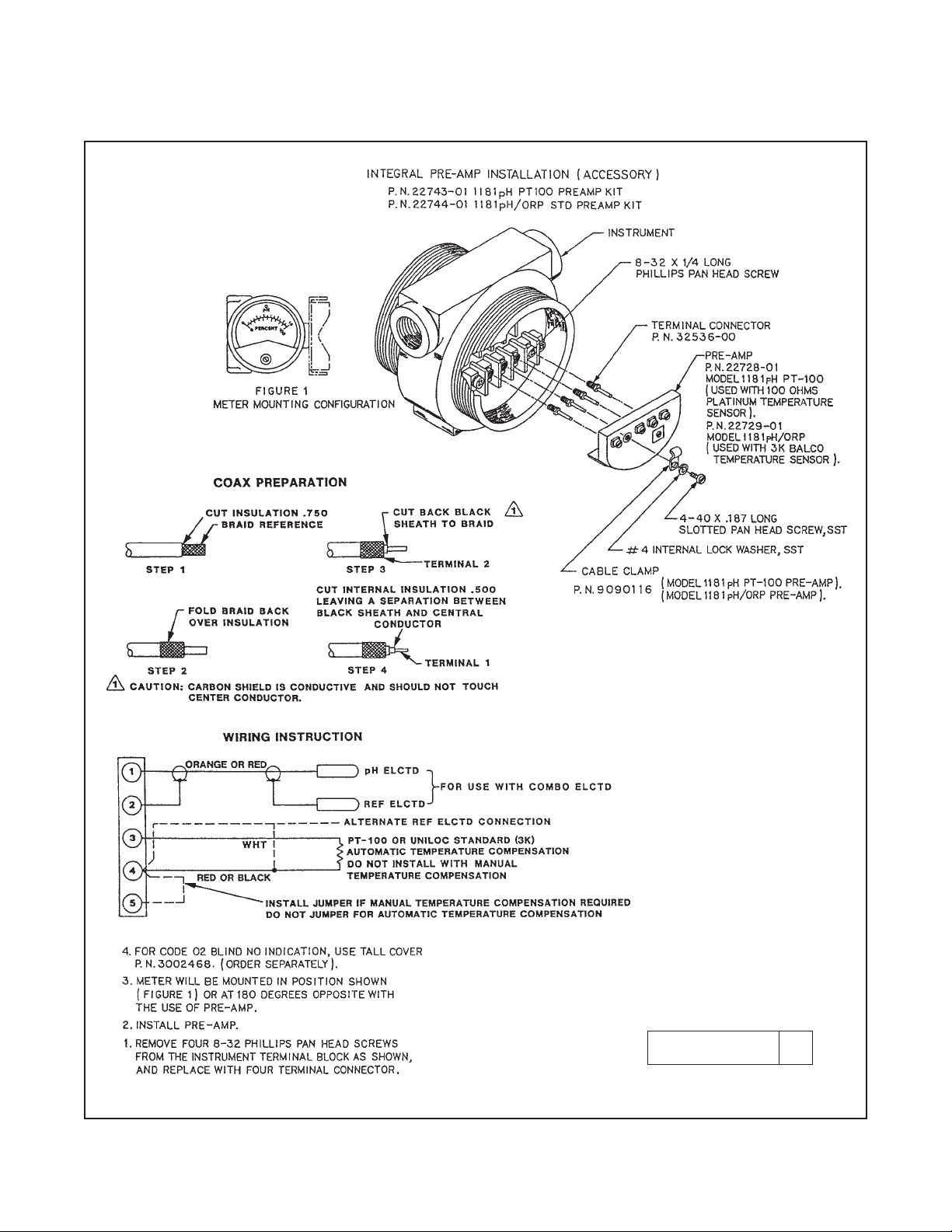
The 1181pH Transmitter is available with an integral preamp. The
Code 43 integral preamp is for use with sensors having a PT100 temperature compensator and the Code 44 internal preamp is for use with
the Rosemount Analytical standard 3K temperature compensator. An
integral preamp is not compatible with the Code 04 LCD display and
Code 02 Blind. These options require a Tall Housing Cover (P/N
3002468). The maximum recommended distance between the sensor
and integral preamp is 15 feet (4.5 meters).
PERFORMANCE SPECIFICATIONS @ 25°C
(Electronics only)
Measurement Range: 0-14 pH
Internal Range Select: Any 2 to 14 pH span in one pH steps
Accuracy: ±0.1% F.S.
Stability: ±0.1%/month
Repeatability: ±0.1 pH
Temperature Coefficient: +0.0028 pH/ÞC F.S.
Automatic Temperature Compensations: 0-100ÞC
RECOMMENDED SENSORS:
Model 300 Retractable pH Sensor
Model 320B Flow Through pH Sensor
Model 320HP High Purity pH Sensor
Model 328A Steam Sterilizable pH Sensor
Model 381 Insertion/Submersion/Flow pH Sensor
Model 385 Retractable pH Sensor
Model 389 Disposable ORP Sensor
Model 396 TUpH Disposable Sensor
Model 399 Disposable pH Sensor
1.5 MODEL 1181ORP TRANSMITTER The Model 1181
ORP Transmitter measures over the range of ±1200 mV. The 4-20
mA isolated output may be calibrated to represent any 200 to 2400
mV range.
PERFORMANCE SPECIFICATIONS @ 25°C
Measurement Ranges Span: 200 mV to 2400 mV in 200 mV steps
Zero: 0 to ± 1200 mV in 200 mV steps
Accuracy: ±0.1% full scale
±2.0 mV full scale
Stability: ±0.1% F.S./month
±2.0 mV/month non-cumulative
Repeatability: ±2.0 mV/month
±0.1% full scale
Temperature Coefficient: ±0.4 mV/°C F.S.
±200 ppm/°C full scale
Automatic Temperature Compensations: N/A
RECOMMENDED SENSORS:
Model 300 Retractable ORP Sensor
Model 330B Flow Through ORP Sensor
Model 381 Insertion/Submersion/Flow ORP Sensor
Model 385 Retractable ORP Sensor
Model 389 Disposable ORP Sensor
Model 399 Disposable ORP Sensor
4
MODEL 1181 pH/ORP SECTION 1.0
INTRODUCTION
MODEL
1181 TWO-WIRE TRANSMITTER
CODE INPUT (Required Selection)
pH pH measurement in an aqueous solution
ORP Oxidation Reduction Potential
CODE DISPLAY (Required Selection)
01 Analog display
02 Blind, without indication
03 Analog display
06 Digital display
CODE OPTIONS
07 Two-inch pipe/wall mounting bracket
11 Stainless steel nameplate (specify marking)
CODE AGENCY APPROVALS
67 FM Explosion proof and Intrinsically Safe
69 CSA Explosion proof and Intrinsically Safe
73 CENELEC Intrinsically Safe/CE (not available with Code 01)
1181 pH 01 07-11 67 EXAMPLE
1.6 ORDERING INFORMATION
Model 1181 Two Wire Transmitter is housed in a NEMA 7B explosion-proof, 4X weatherproof, corrosion-resistant enclosure and includes all
the circuitry necessary for measurement and transmission of an isolated 4-20 mA signal. The transmitter may be selected with or without an
analog or digital display.
5
MODEL 1181 pH/ORP SECTION 2.0
INSTALLATION
SECTION 2.0
INSTALLATION
2.1 GENERAL. The transmitter may be installed in
harsh environmental locations. The transmitter should,
however, be located to minimize the effects of temperature gradients and temperature fluctuations, and to
avoid vibration and shock.
CAUTION
AVOID GROUND LOOPS:(Sensor's shield
wire must not contact a grounded surface).
1. Use well insulated wire. Clean up all
metal burrs on conduit before pulling
cable.
2. Follow wiring instructions for the sensor. Shields aren't grounded on our
analyzers.
3. Seal the sensor conduit from liquids,
which can cause a short.
NOTE
Intrinsically safe units must be installed in
accordance with their designated drawing
numbers. See Section 2.5 for details.
Further non-certified components CANNOT be substituted with certified units.
This would void all certifications.
2.2 MECHANICAL INSTALLATION. Two threaded
mounting holes are located in the bottom of the transmitter housing (see Figure 2-1). These holes are provided for mounting to a flat surface or for attaching the
transmitter to the pipe mounting bracket (see Figure 21 ).
NOTE
If the transmitter is mounted in a vertical
position, the sensor leads should come into
the top of the housing and the power leads
should come into the bottom of the housing.
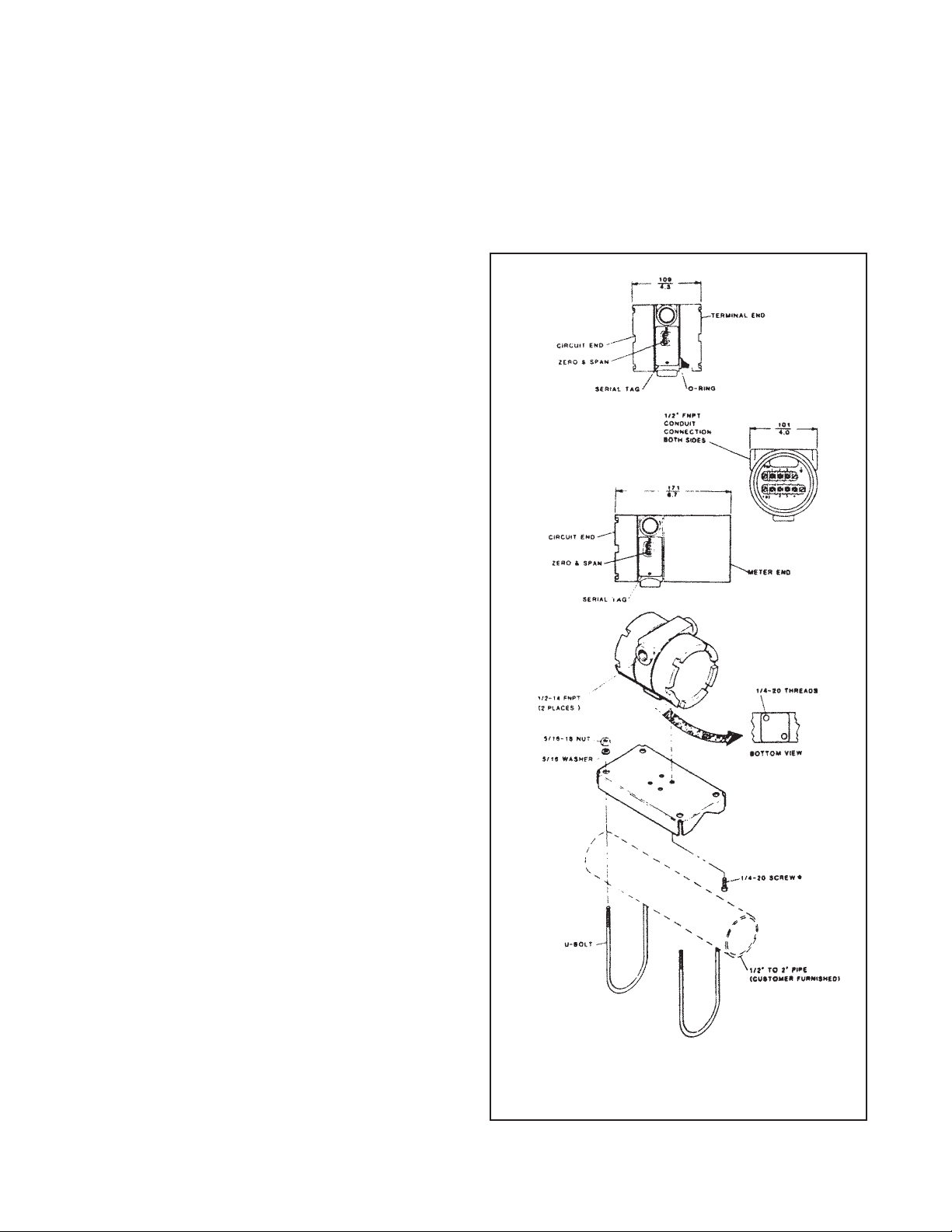
FIGURE 2-1. Transmitter Mounting Details
6
MODEL 1181 pH/ORP SECTION 2.0
INSTALLATION
2.3 ELECTRICAL INSTALLATION. The transmitter
has two ¼-inch conduit openings, one on each side of
the housing. One opening is for the power or signal
wiring, and the other is for the input wiring from the
sensor.
NOTE
On models with the meter, make sure the
meter wiring is securely connected after
the signal and input wiring have been
attached.
2.3.1 Sensor input wiring terminals are located on the
side of the housing designated TERM SIDE on the
serial label, and are the lower set of terminals (TB2).
Remove the end cap from the TERM SIDE of the housing to gain access to the terminals (see Figure 2-2).
If the Model1181pH/ORP transmitter has been supplied with an integral preamplifier (Code Preamp
Options 43 or 44), please refer to Figure 2-3 Integral
Preamp Installation, and Figure 2-4 Wiring Details
Integral Preamp for sensor input wiring instructions.
2.3.2 Power and signal wiring terminals are located
directly above the sensor input wiring terminals and
are designated TBl. For models with a meter, the terminals leads are also attached to TBl.
2.3.3. Conduit connection on the transmitter housing
should be sealed or plugged (using a sealing compound) to avoid accumulation of moisture in housing. If
the connections are not sealed, the transmitter should
be mounted with the electrical housing downward for
draining.
2.3.4. The transmitter case shall be grounded. Power
supply regulation is not critical. Even with the power
supply ripple, of one volt peak to peak, the ripple in the
output signal would be negligible.
NOTE
For best EMI/RFI protection, the power supply/signal cable must be shielded and placed
in an earth grounded, rigid metal conduit.
Connect the outer shield to the earth ground
terminal provided next to TB1.
The sensor cable should also be shielded.
Connect the sensor cable’s outer shield to the
transmitter’s earth ground via the ground terminal next to TB1. If the sensor cable’s outer
shield is braided an appropriate metal cable
gland fitting may be used to connect the braid
to earth ground via the instrument case.
A new addition to the suite of tests done to
ensure CE compliance is IEC 1000-4-5. This is
a surge immunity test that simulates overvoltages due to switching and lightning transients.
In order to meet the requirements of this test,
additional protection must be added to the
instrument in the form of a Transient Protector
such as the Rosemount Model 470D. This is a
3½-inch tube with ½-inch MNPT threads on
both ends. Inside the tube are gas discharge
and zener diode devices to limit surges to the
transmitter from the current loop. No additional
protection is needed on the sensor connections.
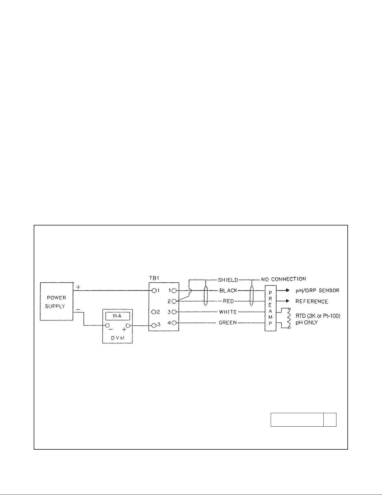
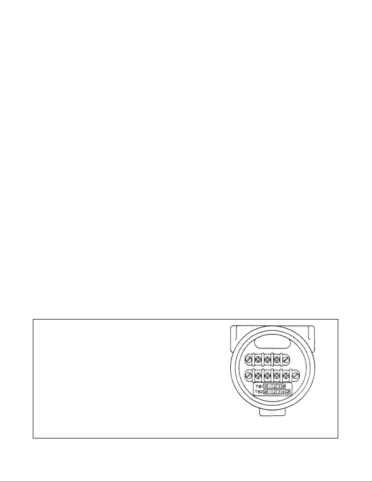
FIGURE 2-2. Transmitter Wiring Detail
TB1-1 Loop Signal (Power Supply + Vdc)
TB1-2 Meter (+) Red
TB1-3 Meter (–) Black & Loop Signal (4-20 mA Output)
TB2-1 pH/ORP Signal (Black)
TB2-2 Reference (Shield) & TC (Red)
TB2-3 Preamp (+5V, White)
TB2-4 Preamp (–5V, Green)

7
MODEL 1181 pH/ORP SECTION 2.0
INSTALLATION
2.4 HAZARDOUS LOCATIONS-EXPLOSION PROOF
INSTALLATIONS. In order to maintain the explosion
proof rating for installed transmitter, the following conditions must be met.
1. The transmitter enclosure covers must be on hand
tight and the threads must not be damaged.
NOTE
These covers seat on rings which serve to
provide a dust proof enclosure for Class II
and Class III installations.
2. Explosion proof "Y" fittings must be properly
installed and plugged with a sealing compound to
prevent explosive gases from entering the transmitter. CSA has determined that the transmitter
housing is "Factory Sealed". Installation of "Y" fittings and the use of sealing compound is not
required for CSA approved Explosion Proof installations.
NOTE
Do not install sealing compound until all
field wiring is completed.
CAUTION
Sealing compound must be installed prior
to applying power to the transmitter.
3. If one of the conduit connections on the housing is
not used, it must be closed with a threaded metal
plug with at least five threads engaged.
4. The serial tag cover on the external ZERO and
SPAN adjustments must be in place.
6. Explosion proof installation must be in accordance
with Drawing Number 1400155 (see Figure 2-12).
5. For sensors in hazardous area locations, explosion proof junction boxes can be provided to
house the preamplifier. This does not warrant the
pH or ORP sensor explosion-proof. Maximum
safety can be achieved by installing an intrinsically
safe system where Hazardous Area requirements
must be met.
2.5 HAZARD LOCATIONS - INTRINSICALLY SAFE
INSTALLATIONS. To secure and maintain intrinsically
safe installations for the appropriate approval agency,
the following conditions must be met:
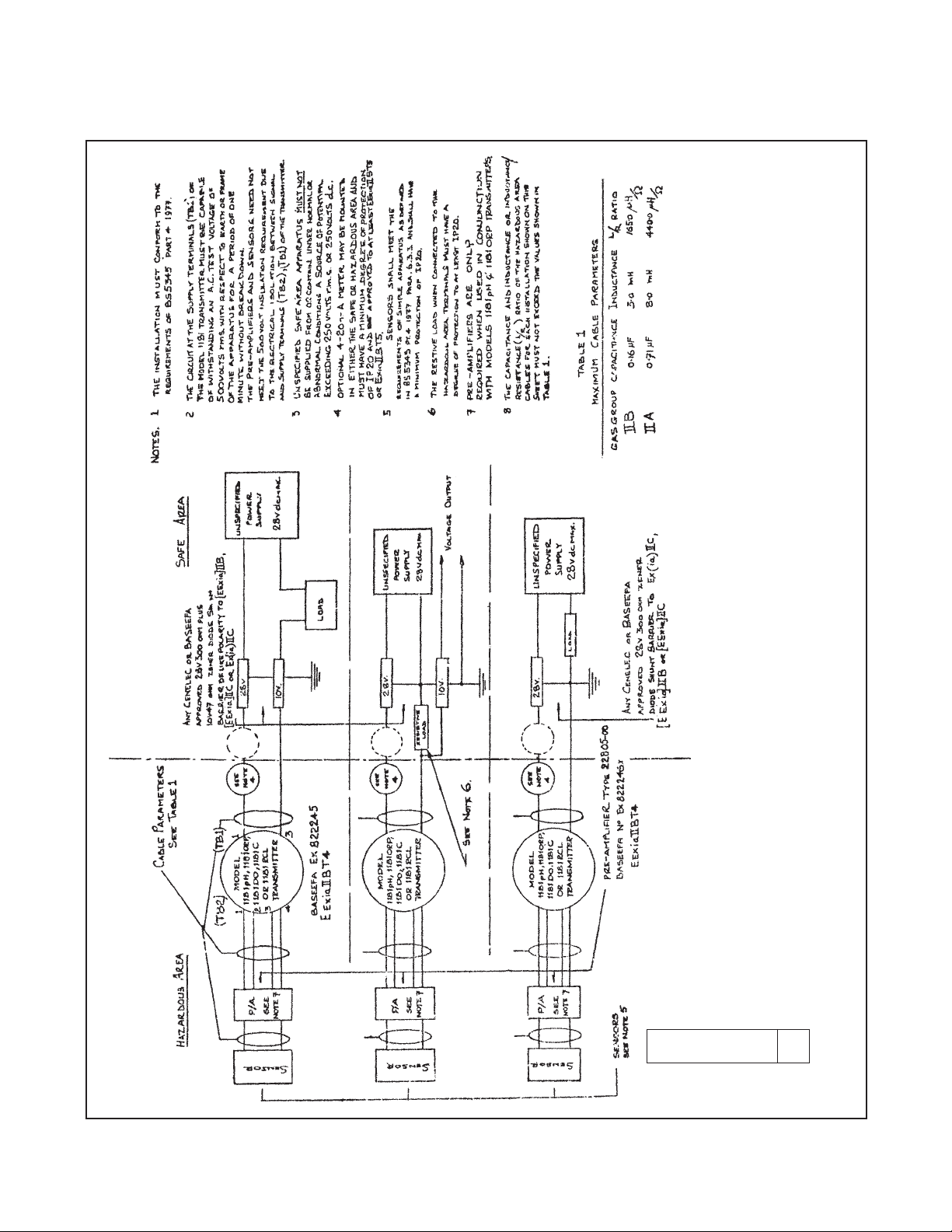
1. Code 73 must be specified when ordering CENELEC/BASEEFA units. Installation must be performed in accordance with Drawing Number
1400143 (see Figures 2-5, 6 & 7).
2. Code 69 must be specified when ordering C.S.A.
(Canadian Standards Association) units.
Installation must be in accordance with Drawing
Number 1400123 (see Figure 2-8).
3. Code 67 must be specified when ordering F.M.
(Factory Mutual) units. Approved “Entity” installation must be in accordance with Drawing Number
1400153 (see Figures 2-9, 2-10, and 2-11).
8
MODEL 1181 pH/ORP SECTION 2.0
INSTALLATION
FIGURE 2-3. Integral Preamp Installation
DWG. NO. REV.
40118154 C
9
MODEL 1181 pH/ORP SECTION 2.0
INSTALLATION
FIGURE 2-4. Wiring Details Integral Preamp
DWG. NO. REV.
40118119 C
10
MODEL 1181 pH/ORP SECTION 2.0
INSTALLATION
FIGURE 2-5. Installation of 1181 Series for Intrinsically Safe Operation (CENELEC) Page 1 of 3
DWG. NO. REV.
1400143 C
 Loading...