

Rosemount Manual: 1085B-C Conductivity Microprocessor Analyzer | Rosemount Manuals & Guides

Model 1054B C
Conductivity Microprocessor Analyzer
Instruction Manual
PN 51-1054BC/rev.B
April 2003

WARNING
ELECTRICAL SHOCK HAZARD
Making cable connections to and servicing this instrument require access to shock hazard level voltages
which can cause death or serious injury.
Relay contacts made to separate power sources
must be disconnected before servicing.
Electrical installation must be in accordance with
the National Electrical Code (ANSI/NFPA-70)
and/or any other applicable national or local
codes.
Unused cable conduit entries must be securely
sealed by non-flammable closures to provide
enclosure integrity in compliance with personal
safety and environmental protection requirements.
For safety and proper performance this instrument must be connected to a properly grounded
three-wire power source.
Proper relay use and configuration is the responsibility of the user.
Do not operate this instrument without front cover
secured. Refer installation, operation and servicing
to qualified personnel.
Be sure to disconnect all hazardous voltage before
opening the enclosure.
The unused conduit openings need to be sealed
with NEMA 4X or IP65 conduit plugs to maintain
the ingress protection rating (IP65).
No external connection to the instrument of more
than 43V peak allowed with the exception of power
and relay terminals. Any violation will impair the
safety protection provided.
ESSENTIAL INSTRUCTIONS
READ THIS PAGE BEFORE PRO-
CEEDING!
Rosemount Analytical designs, manufactures, and tests its
products to meet many national and international standards. Because these instruments are sophisticated technical products, you must properly install, use, and maintain
them to ensure they continue to operate within their normal
specifications. The following instructions must be adhered
to and integrated into your safety program when installing,
using, and maintaining Rosemount Analytical products.
Failure to follow the proper instructions may cause any one
of the following situations to occur: Loss of life; personal
injury; property damage; damage to this instrument; and
warranty invalidation.
• Read all instructions prior to installing, operating, and
servicing the product. If this Instruction Manual is not the
correct manual, telephone 1-949-757-8500 and the
requested manual will be provided. Save this Instruction
Manual for future reference.
• If you do not understand any of the instructions, contact
your Rosemount representative for clarification.
• Follow all warnings, cautions, and instructions marked
on and supplied with the product.
• Inform and educate your personnel in the proper installation, operation, and maintenance of the product.
• Install your equipment as specified in the Installation
Instructions of the appropriate Instruction Manual and
per applicable local and national codes. Connect all
products to the proper electrical and pressure sources.
• To ensure proper performance, use qualified personnel
to install, operate, update, program, and maintain the
product.
• When replacement parts are required, ensure that qualified people use replacement parts specified by
Rosemount. Unauthorized parts and procedures can
affect the product’s performance and place the safe
operation of your process at risk. Look alike substitutions may result in fire, electrical hazards, or improper
operation.
• Ensure that all equipment doors are closed and protective covers are in place, except when maintenance is
being performed by qualified persons, to prevent electrical shock and personal injury.
WARNING
This product is not intended for use in the light industrial,
residential or commercial environment, per the instrument’s
certification to EN50081-2.
Emerson Process Management
Rosemount Analytical Inc.
2400 Barranca Parkway
Irvine, CA 92606 USA
Tel: (949) 757-8500
Fax: (949) 474-7250
http://www.RAuniloc.com
© Rosemount Analytical Inc. 2001


MODEL 1054B C TABLE OF CONTENTS
MODEL 1054B CONDUCTIVITY MICROPROCESSOR ANALYZER
TABLE OF CONTENTS
Section Title Page
1.0 DESCRIPTION AND SPECIFICATIONS........................................................... 1
1.1 Features and Applications ................................................................................. 1
1.2 Specifications .................................................................................................... 2
1.3 Ordering Information.......................................................................................... 4
2.0 INSTALLATION.................................................................................................. 5
2.1 General.............................................................................................................. 5
2.2 Unpacking and Inspection ................................................................................. 5
2.3 Mechanical Installations .................................................................................... 5
2.4 Electrical Wiring................................................................................................. 6
3.0 DESCRIPTION OF CONTROLS ....................................................................... 14
3.1 Keyboard Functions........................................................................................... 14
3.2 Item Selection and Value Adjustment Keys....................................................... 15
4.0 CONFIGURATION............................................................................................. 19
4.1 General ............................................................................................................. 19
4.2 Alarm 1 and 2 ................................................................................................... 21
4.3 Interval Timer .................................................................................................... 22
4.4 Temperature ..................................................................................................... 23
4.5 Current Output .................................................................................................. 23
4.6 Defaults ............................................................................................................. 24
4.7 Alarm Setpoint ................................................................................................... 25
4.8 Output Scale Expansion .................................................................................... 26
4.9 Simulate Output................................................................................................. 27
5.0 START-UP AND CALIBRATION........................................................................ 28
5.1 General.............................................................................................................. 28
5.2 Entering Cell Constant....................................................................................... 28
5.3 Temperature Calibration .................................................................................... 28
5.4 Initial Loop Calibration ....................................................................................... 28
5.5 Routine Standardization .................................................................................... 30
5.6 Sensor Maintenance.......................................................................................... 30
6.0 KEYBOARD SECURITY ................................................................................... 31
6.1 General.............................................................................................................. 31
6.2 Access Code ..................................................................................................... 31
7.0 THEORY OF OPERATION................................................................................ 31
8.0 DIAGNOSTICS AND TROUBLESHOOTING .................................................... 32
8.1 Diagnostics ........................................................................................................ 32
8.2 Troubleshooting................................................................................................. 33
8.3 Instrument Maintenance .................................................................................... 35
9.0 RETURN OF MATERIAL................................................................................... 37
i

MODEL 1054B C TABLE OF CONTENTS
LIST OF FIGURES
Figure No. Title Page
2-1 Panel Mounting Cutout...................................................................................... 7
2-2 Panel Mounting Tab Installation......................................................................... 8
2-3 Wall Mounting J-Box Installation........................................................................ 9
2-4 Wall Mounting J-Box Wiring............................................................................... 10
2-5 Pipe Mounting Installation ................................................................................. 11
2-6 Electrical Wiring................................................................................................. 12
2-7 Wall Mount Enclosure (Option -20).................................................................... 13
3-1 Function Select on Keypad................................................................................ 14
3-2 Accessing Editing Function ............................................................................... 14
3-3 Accessing Configuration Menus........................................................................ 14
3-4 LCD Display....................................................................................................... 15
3-5 Set Menu Items ................................................................................................. 18
4-1 Alarm 1 and 2 Configuration.............................................................................. 21
4-2 Interval Timer Configuration .............................................................................. 22
4-3 Timer Diagram for One Cycle ............................................................................ 22
4-4 Temperature Configuration................................................................................ 23
4-5 Current Output Configuration ............................................................................ 23
4-6 Default Configuration......................................................................................... 24
4-7 Alarm Setpoint................................................................................................... 25
4-8 Output Scale Expansion.................................................................................... 26
4-9 Simulate Current Output.................................................................................... 27
8-1 Simulate Conductivity Input............................................................................... 36
LIST OF TABLES
Table No. Title Page
1-1 Conductivity Range ........................................................................................... 3
1-2 Replacement Parts............................................................................................ 4
1-3 Accessories ....................................................................................................... 4
3-1 Key Description ................................................................................................. 16
3-2 Information Mnemonics ..................................................................................... 17
3-3 Set Function Mnemonics................................................................................... 17
4-1 Configuration Work Sheet ................................................................................. 20
4-2 Relay States for Various Conditions and Alarm/Default Configurations ............ 24
8-1 Fault Mnemonics ............................................................................................... 32
8-2 RTD Resistance Values..................................................................................... 32
8-3 Troubleshooting Guide ...................................................................................... 34
ii

1
MODEL 1054B C SECTION 1.0
DESCRIPTION AND SPECIFICATIONS
SECTION 1.0
DESCRIPTION AND SPECIFICATIONS
1.1 FEATURES AND APPLICATIONS
The Model 1054B Microprocessor Analyzers, with the
appropriate sensors, are designed to continuously measure and control pH, ORP, conductivity, resistivity, ratio,
percent concentration, dissolved oxygen, ozone or total
free chlorine in industrial and municipal processes.
The Model 1054B Conductivity Analyzers are housed in
a NEMA 4X (IP65) weatherproof, corrosion-resistant,
flame retardant enclosure suitable for panel, pipe or wall
mounting. All functions are accessed through the front
panel membrane keyboard which features tactile feedback. Measurement data may be read at any time.
However, settings may be protected against accidental
or unauthorized changes by a user selectable security
code. The display indicates the measured value in engineering units as well as temperature, alarm status, hold
output and fault conditions.
The 1054B transmits a user selected isolated current
output which is continuously expandable over the measurement range for either direct or reverse action and can
be displayed in milliamps or percent. Output dampening
of 0-255 sec. is user selectable.
The output and relay default settings are user selectable
for hold or fault mode operation. The hold output function
allows manual control during routine sensor maintenance.
Continuous self diagnostics alert the operator to faults
due to analyzer electronics, integral RTD failures, open
wiring and process variable range problems. In the event
of a fault condition or hold mode diagnosed by the analyzer, the output will be set to a preset or last process
value and the relays will be set to their default settings.
Dual alarms are a standard feature on the Model 1054B
and are programmable for either high or low operation.
Alarm 2 may be programmed as a fault alarm. Both
alarms feature independent setpoints, adjustable hysteresis and time delay action. The time delay is convenient when an alarm is used for corrective action, such as
shutting down a demineralizer for regeneration. Time
delay will ignore a temporary breakthrough and prevent
shutting down a demineralizer unit prematurely. A dedicated interval timer with relay is also provided.
Automatic or manual temperature compensation is keyboard selectable. The process temperature is accurately
measured from an integral RTD in the sensor assembly
and is read on the display. For greater accuracy, the temperature indication may be standardized to the process
temperature. The temperature may be configured to read
in °C or °F.
Calibration is easily accomplished by simply immersing
the sensor in a known solution and entering the value.
With a two point calibration, the Model 1054B will automatically calculate the temperature slope of the solution.
Upon routine standardization a sensor cell factor value is
calculated, and a trend of this value can be used to track
sensor coating.
The Model 1054B Microprocessor Analyzer comes standard with an LCD display. An LED display is available as
an option.
• SELF DIAGNOSTICS with a user selectable fault alarm.
• KEYBOARD SECURITY is user selectable.
• NO BATTERY BACK-UP REQUIRED. Non-volatile EEPROM memory.
• DUAL ALARMS WITH PROGRAMMABLE LOGIC. A third relay is provided with timer functions.
• PROGRAMMABLE OUTPUT AND RELAY DEFAULTS for hold and fault modes.
• NEMA 4X (IP65) WEATHERPROOF CORROSION-RESISTANT ENCLOSURE.

2
Model 1054B C SECTION 1.0
DESCRIPTION AND SPECIFICATIONS
1.2 SPECIFICATIONS -
Enclosure: Black, ABS, NEMA 4X, IP65,
CSA Enclosure 4
144 X 144 X 192 mm
(5.7 X 5.7 X 7.6 in.)
Wall Mount Enclosure: NEMA 4X, Heavy duty
fiberglass, reinforced thermoplastic.
356.4 X 450.1 X 180.2 mm* (14 X 17.7 X 7.1 in.*)
Front Panel: Membrane keyboard with tactile feed-
back and user selectable security
Digital Display: LCD, black on grey
Optional, red LED
Character Height: 18 mm (0.7 in.)
Electrical Classification:
FM Class I, Div. 2, Group A thru D
28 Vdc relays - 5.0 amps resistive only
150 mA - Groups A & B; 400 mA - Group C ;
540 mA - Group D; Ci = 0; Li = 0
CSA Class I, Div. 2, Group A thru D.
28 Vdc, 110 Vac & 230 Vac relays
5.0 Amps resistive only
Wall Mount Enclosure: General Purpose
Power: 100 - 127 VAC, 50/60 Hz ± 6%, 4.0 W
200 - 253 VAC, 50/60 Hz ± 6%, 4.0 W
Current Output: Isolated, 0-20 mA or 4-20 mA into
600 ohms maximum load at 115/230 Vac or
550 ohms maximum load at 100/200 Vac,
Direct or Reverse
Output Dampening: 0-255 seconds
Code -20 Wall Mount Enclosure does not meet CE requirements
*Includes latches and mounting feet
EMI/RFI: EN61326
LVD: EN61010-1
Ambient Temperature: -20 to 65°C (-4 to 149
°
F)
Ambient Humidity: LED max 95% RH
(LCD max 85% RH @ 50°C)
Alarms: Dual, field selectable High/Low, High/High,
Low/Low
Alarm 2 configurable as a fault alarm
Time Delay 0 to 254 seconds
Dual Setpoints, continuously adjustable
Hysteresis is adjustable up to 25% full scale
for low side/High Alarm and high side/Low Alarm
Interval Timer: Interval: 10 min. to 2999 days
On Counts: 1 to 60
On Duration: 1 to 299.9 seconds
Off Duration: 1 to 299.9 seconds
Wait Duration: 1 to 299.9 seconds
Controls dedicated relay
Relay Contacts: Epoxy Sealed Form A contacts,
SPST, Normally Open.
Resistive
Inductive
28 VDC 5.0 Amps 3.0 Amps
115 VAC 5.0 Amps 3.0 Amps
230 VAC 5.0 Amps 1.5 Amps
Weight/Shipping Weight: 1.1 kg/1.6 kg (2.5 lb/3.5 lb)

3
Model 1054B C SECTION 1.0
DESCRIPTION AND SPECIFICATIONS
The Model 1054B Conductivity Analyzer measures over the range of 0-2 µS/cm to 0-1,000 mS/cm.
Temperature slope may be adjusted anywhere between 0 and 5% to provide greater accuracy in chemical concentration control. The temperature slope is factory set at 2% as a representative value, but each conductive
solution has its own set of temperature vs. concentration curves. The Model 1054B C will automatically calculate the temperature slope for any given solution, or permit manual adjustment of the temperature slope if
already known. On calibration the analyzer will also automatically correct for cell constant variations for better
measurement accuracy.
ANALYZER SPECIFICATIONS @ 25°C
Measurement Range: (See Table 1)
Output Scale: Zero suppression: up to 90% full scale.
Span: from 10% to 100% full scale
Accuracy: ±0.5% of reading
Repeatability: ±0.25% of reading
Stability: ±0.25% month, non-cumulative
Temperature Effect: 0.02% of reading/°C
Temperature Compensation: -20 to 200°C
(-4 to 392°F) (automatic or manual)
Temperature Slope Adjustment: 0-5%/
°
C
RECOMMENDED SENSORS:
Model 140 Retractable Conductivity
Model 150 Insertion/Submersion Conductivity
Model 400 Screw-in Conductivity
Model 401-14 Screw-in Conductivity
Model 402 Retractable Conductivity
Model 403 Sanitary Flange Conductivity
Model 404 Low Flow Conductivity
FULL SCALE MICROSIEMENS/cm
TABLE 1-1. CONDUCTIVITY RANGE
Conductivity Sensor 150 140
Model Number 400 140 150 150
402/403 400/402/403
404
Cell Constant 0.1 0.2 0.5 1.0
Min. Range 2 4 100 200
Max. Range* 2,000 4,000 10,000 20,000
* Values shown are absolute conductivi-
ty. Maximum range will be reduced for
compensated conductivity at elevated
process temperatures.
4
MODEL 1054B C SECTION 1.0
DESCRIPTION AND SPECIFICATIONS
1.3 ORDERING INFORMATION
The Model 1054B Microprocessor Analyzer: Housed in a corrosion resistant, weatherproof enclosure and oper-
ates on either 115 or 230 VAC, 50/60 Hz power. Standard features include digital display, isolated current output,
dual alarms, and automatic and manual temperature compensation.
MODEL
1054B MICROPROCESSOR ANALYZER (3.5 lbs/1.5 kg)
Code Measurement
C Contacting Conductivity
T Toroidal Conductivity
P/N DESCRIPTION
22966-00 PCB, LCD Digital Display
23025-01 Panel Mounting Kit
23739-00 PCB, Power Supply
23664-01 PCB, CPU, Conductivity
23245-01 PCB, LED Digital Display
23740-00 PCB, Motherboard
23695-04 Keyboard Overlay, LCD Version
23695-05 Keyboard Overlay, LED Version
33469-00 Enclosure, Body
33470-00 Enclosure, Rear Cover
32938-00 Gasket, Rear Cover
9100157 Fuse, 0.1A, 3AB, 250V, Slo-Blow
9100160 Fuse, .250A, 125V
9100189 Fuse, .750A, 125V
TABLE 1-2. Replacement Parts
CODE STANDARD ENCLOSURE OPTIONS
01 LCD Display
02 LED Display
CODE OPTIONS
20 Wall Mount Enclosure
1054BC 01 20 EXAMPLE
TABLE 1-3. Accessories
P/N DESCRIPTION
2001492 Tag, Stainless Steel, Specify
Marking
23053-00 Mounting Bracket, 2-inch Pipe
23054-01 Mounting Bracket, Wall, with
Junction Box
23268-01 Heater, 115 VAC, 50/60 Hz,
1054B (Code 20 Only)
23268-02 Heater, 230 VAC, 50/60 Hz,
1054B (Code 20 Only)

5
MODEL 1054B C SECTION 2.0
INSTALLATION
SECTION 2.0
INSTALLATION
2.1 GENERAL. Installation must be performed by a
trained technician. This analyzer's enclosure is suitable for outdoor use. However, it should be located in
an area where temperature extremes and vibrations
are minimized or absent. Installation must be performed by a trained technician.
2.2 UNPACKING AND INSPECTION. Inspect the
analyzer for shipping damage. If damaged, notify the
carrier immediately. Confirm that all items shown on
the packing list are present. Notify Rosemount
Analytical if items are missing.
2.3 MECHANICAL INSTALLATION. Select an instal-
lation site that is at least one foot from any high voltage conduit, has easy access for operating personnel,
and is not in direct sunlight. Mount the analyzer as follows:
1. Remove the four screws that secure the rear
cover of the enclosure.
2. Remove the four screws holding the front panel
assembly of the enclosure and carefully pull the
front panel and connected printed circuit boards
straight out.
3. Follow the procedure for the appropriate mounting
configuration: Section 2.3.1 for panel mounting,
Section 2.3.2 for wall mounting, Section 2.3.3 for
pipe mounting.
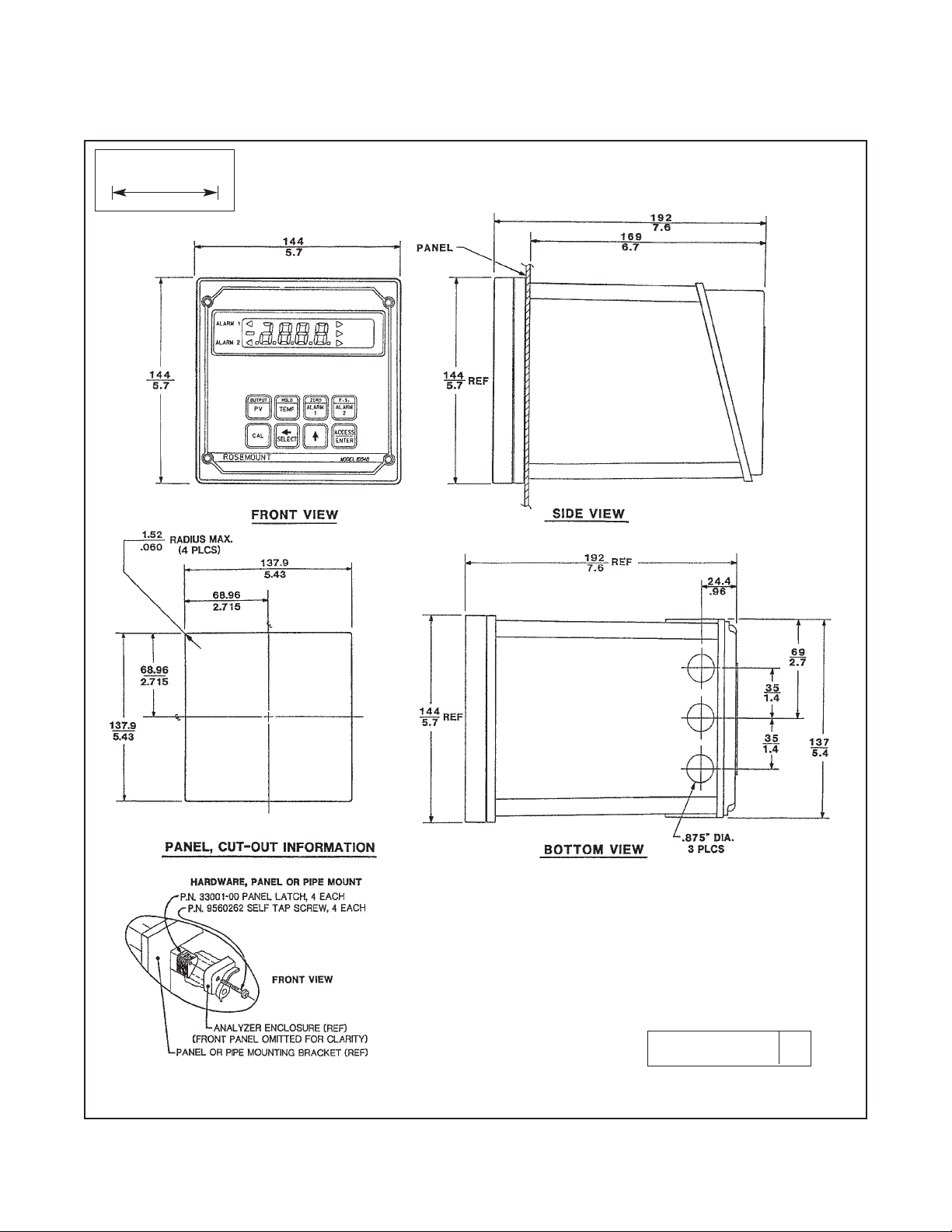
2.3.1 Panel Mounting (Standard). The Model 1054B
is designed to fit into a DIN standard 137.9 mm x
137.9 mm (5.43 in. x 5.43 in.) panel cutout (Refer to
Figure 2-1 and Figure 2-2).
1. Prepare the analyzer as described in Section 2.3.
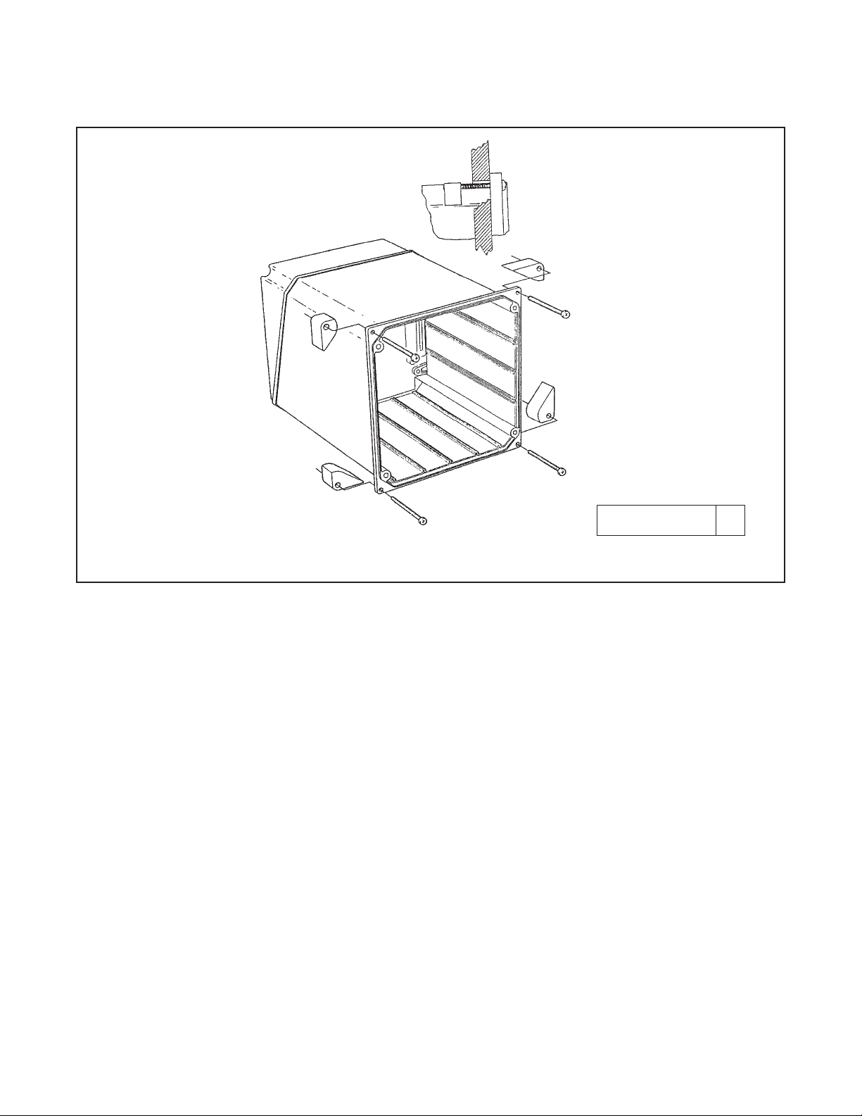
2. Install the mounting latches as described in Figure
2-2 (latches are shown oversize for clarity). If the
latches are not installed exactly as shown, they
will not work correctly. The screws provided are
self-tapping. Tap the screw the full depth of the
mounting latch (refer to side view) leaving a gap
greater than the thickness of the cutout panel.
3. Align the latches as shown and insert the analyzer enclosure through the front of the panel cutout.
Tighten the screws for a firm fit. To avoid damaging the mounting latches, do not use excessive
force.
4. Replace the front panel assembly. Circuit boards
must align with the slots on the inside of the
enclosure. Assure that the continuity wire is connected to the rear cover and the interface board’s
closest mounting screw. Replace the door and
four front panel screws.
2.3.2 Wall Mounting Plate with Junction Box
(P/N 23054-01). Refer to Figure 2-3 and Figure 2-4.
1. Prepare the analyzer as described in Section 2.3.
2. Mount the junction box and bracket to the analyzer with the hardware provided. All wiring can be
brought to the terminal strip prior to mounting the
analyzer.
3. Place the metal stiffener on the inside of the analyzer and mount the two 1/2-inch conduit fittings
using two each weather seals as shown. Mount
NEMA 4X conduit plug (included) into center conduit hole.
4. Mount the analyzer to the junction box using the
1/2-inch conduit fittings.
5. Complete wiring from the analyzer to the junction
box (Refer to Figure 2-4).
NOTE
Run sensor wiring out of the left opening
(From front view) to J-Box. All others out
right opening to J-Box.
2.3.3 Pipe Mounting (P/N 23053-00). The 2-inch pipe
mounting bracket includes a metal plate with a cutout
for the analyzer (Refer to Section 2.3 for mounting the
analyzer into the plate). Mounting details are shown in
Figure 2-5.
2.3.4 Wall Mount Enclosure (option -20). See
Figure 2-7 for installation details.

6
MODEL 1054B C SECTION 2.0
INSTALLATION
2.4 ELECTRICAL WIRING. The Model 1054B has
three conduit openings in the bottom rear of the analyzer housing which will accommodate 1/2-inch conduit fittings. From the front view, the conduit opening
on the left is for sensor wiring; the center is for signal
output and the opening on the right is for timer, alarm,
and AC connections. Sensor wiring should always be
run in a separate conduit from power wiring. AC
power wiring should be 14 gauge or greater.
NOTE
For maximum EMI/RFI protection the
output cable should be shielded and
enclosed in an earth grounded, rigid
metal conduit. When wiring directly to
the instrument connect the output
cable’s outer shield to the transmitter’s
earth ground via terminal 8 on TB3.
When wiring to the wall mounting junction box connect the output cable’s outer
shield to the earth ground terminal on
TB-A.
The sensor cable should also be shielded. When wiring directly to the instrument connect the sensor cable’s outer
shield to the transmitter’s earth ground
via terminal 8 of TB-2. If the sensor
cable’s outer shield is braided an appropriate metal cable gland fitting may be
used to connect to braid to earth ground
via the instrument case. When wiring to
the wall mounting junction box connect
the sensor cable’s outer shield to the
earth ground terminal on TB-A.
The user must provide a means to disconnect the main power supply in the
form of circuit breaker or switch. The circuit breaker or the switch must be located in close proximity to the instrument
and identified as the disconnecting
device for the instrument.
2.4.1 Power Input Wiring. The Model 1054B can be
configured for either 115 VAC or 230 VAC power.
Connect AC power to TB1-8 and -9 (115 VAC) or TB17 and -8 (230 VAC) ground to the ground terminal at
TB3-8 (refer to Figure 2-6).
CAUTION
The sensitivity and stability of the analyzer
will be impaired if the input wiring is not
grounded. DO NOT apply power to the
analyzer until all electrical connections are
verified and secure. The following precautions are a guide using UL 508 as a safeguard for personnel and property.
1. AC connections and grounding must be in compliance with UL 508 and/or local electrical codes.
2. The metal stiffener is required to provide support
and proper electrical continuity between conduit
fittings.
3. This type 4/4X enclosure requires a conduit hub
or equivalent that provides watertight connect,
REF UL 508-26.10.
4. Watertight fittings/hubs that comply with the
requirements of UL 514B are to be used.
5. Conduit hubs are to be connected to the conduit
before the hub is connected to the enclosure, REF
UL 508-26.10.
6. If the metal support plate is not used, plastic fittings must be used to prevent structural damage
to the enclosure. Also, appropriate grounding lug
and awg conductor must be used with the plastic
fittings.
2.4.2 Output Wiring. The signal output and alarm
connections are made to terminals 1 through 6 of TB1
and TB3-1 and 2. (Refer to Figure 2-6).
7
MODEL 1054B C SECTION 2.0
INSTALLATION
FIGURE 2-1. Panel Mounting Cutout
WHEN INCH AND METRIC DIMS
ARE GIVEN
MILLIMETER
INCH
DWG. NO. REV.
41054B01 B
8
MODEL 1054B C SECTION 2.0
INSTALLATION
FIGURE 2-2. Panel Mounting Tab Installation
DWG. NO. REV.
41054A26 A
 Loading...