

Rosemount Manual: 1055-pH-C pH / Conductivity Analyzer Abridged | Rosemount Manuals & Guides

Model 1055 SOLU COMP®II
Dual Input pH/Conductivity Analyzer
Model Option 1055-22-30
Instruction Sheet
PN 51A-1055pHC/rev.I
January 2006
ESSENTIAL INSTRUCTIONS
READ THIS PAGE BEFORE PROCEEDING!
Your purchase from Rosemount Analytical, Inc. has
resulted in one of the finest instruments available for
your particular application. These instruments have
been designed, and tested to meet many national
and international standards. Experience indicates
that its performance is directly related to the quality of
the installation and knowledge of the user in operating and maintaining the instrument. To ensure their
continued operation to the design specifications, personnel should read this manual thoroughly before
proceeding with installation, commissioning, operation, and maintenance of this instrument. If this
equipment is used in a manner not specified by the
manufacturer, the protection provided by it against
hazards may be impaired.
•Failure to follow the proper instructions may cause
any one of the following situations to occur: Loss of
life; personal injury; property damage; damage to this
instrument; and warranty invalidation.
•Ensure that you have received the correct model and
options from your purchase order. Verify that this manual covers your model and options. If not, call 1-800854-8257 or 949-757-8500 to request correct manual.
•For clarification of instructions, contact your
Rosemount representative.
•Follow all warnings, cautions, and instructions
marked on and supplied with the product.
•Use only qualified personnel to install, operate,
update, program and maintain the product.
•Educate your personnel in the proper installation,
operation, and maintenance of the product.
•Install equipment as specified in the Installation
section of this manual. Follow appropriate local and
national codes. Only connect the product to electrical
and pressure sources specified in this manual.
•Use only factory documented components for repair.
Tampering or unauthorized substitution of parts and
procedures can affect the performance and cause
unsafe operation of your process.
•All equipment doors must be closed and protective
covers must be in place unless qualified personnel
are performing maintenance.
•If this equipment is used in a manner not specified by
the manufacturer, the protection provided by it
against hazards may be impaired.
WARNINGS
RISK OF ELECTRICAL SHOCK
Equipment protected throughout by double insulation.
• Installation of cable connections and servicing of this product
require access to shock hazard voltage levels.
• Main power and relay contacts wired to separate power
source must be disconnected before servicing.
• Do not operate or energize instrument with case open!
• Signal wiring connected in this box must be rated at least 240 V.
• Non-metallic cable strain reliefs do not provide grounding
between conduit connections! Use grounding type bushings and
jumper wires.
• Unused cable conduit entries must be securely sealed by nonflammable closures to provide enclosure integrity in compliance
with personal safety and environmental protection requirements.
Unused conduit openings must be sealed with NEMA 4X or
IP65 conduit plugs to maintain the ingress protection rating
(NEMA 4X).
• Electrical installation must be in accordance with the National
Electrical Code (ANSI/NFPA-70) and/or any other applicable
national or local codes.
• Operate only with front and rear panels fastened and in place
over terminal area.
• Safety and performance require that this instrument be connected and properly grounded through a three-wire power source.
• Proper relay use and configuration is the responsibility of the user.
CAUTION
This product generates, uses, and can radiate radio frequency
energy and thus can cause radio communication interference.
Improper installation, or operation, may increase such interference. As temporarily permitted by regulation, this unit has not
been tested for compliance within the limits of Class A computing devices, pursuant to Subpart J of Part 15, of FCC Rules,
which are designed to provide reasonable protection against
such interference. Operation of this equipment in a residential
area may cause interference, in which case the user at his
own expense, will be required to take whatever measures may
be required to correct the interference.
WARNING
This product is not intended for use in the light industrial,
residential or commercial environments per the instrument’s
certification to EN50081-2.
For additional information, please refer to the Instruction Manuals CD shipped with this
product, or visit our website at www.emersonprocess.com/raihome/liquid/.
2
MODEL SOLU COMP II SPECIFICATIONS
SPECIFICATIONS - General
Case: Polycarbonate (pipe- and surface-mount),
ABS (panel-mount). All versions are NEMA
4X/CSA 4 (IP65).
Dimensions
Panel (code -10): 6.10 x 6.10 x 3.72 in. (155 x
155 x 94.5 mm)
Surface/Pipe (code -11): 6.23 x 6.23 x 3.23 in.
(158 x 158 x 82 mm); see page 5 for dimensions
of pipe mounting bracket.
Conduit openings: Accepts PG13.5 or 1/2 in. con-
duit fittings
Display: Two line, 16-character, back-lit display.
Character height: 4.8 mm. Display can be customized to meet individual requirements.
Depending on number of sensors, as many as 14
display screens are available.
Ambient temperature and humidity: 0 to 50°C, (32
to 122°F) RH 5 to 95% (non-condensing)
Note: The analyzer is operable from -20 to 60°C
(-4 to 140°F) with some degradation in display
performance.
Power:
Code -01:
115/230 Vac ±15%, 50/60 Hz ±6%, 8.0W
Code -02*:
24 Vdc ±15%, 6.0W
Installation Category II
*
For +24Vdc Power Supply use only devices meeting
NEC Class II or UL recognized (UL 1950).
Equipment protected throughout by double insulation.
Hazardous Location:
Class I, Division 2,
Groups A, B, C, & D
POLLUTION DEGREE 4: Extended Environment
Outdoor use where conductive contamination
such as rain, snow, or dust may be present.
(Hazardous Location only)
RFI/EMI: EN-61326
LVD: EN-61010-1
Input: Choice of single or dual sensor input with
measurement choices of pH/ORP, conductivity/
resistivity, toroidal conductivity, flow, chlorine, dissolved oxygen, and dissolved ozone. Field-commissioned units allow user to change measurements on either or both inputs. See combination
guide for valid combinations. For contacting conductivity measurements, temperature element
must be a Pt 1000 RTD. For other measurements, use either a Pt100 RTD, Pt1000 RTD, or
22k NTC (D.O. only).
Outputs: Two 4-20 mA or 0-20 mA isolated outputs.
Continuously adjustable. Linear or logarithmic.
Maximum load 500 ohms. Output dampening with
time constant of 5 sec is user-selectable.
Alarms: Three alarm relays for process measure-
ment(s) or temperature. Alarm 3 can be
configured as a fault alarm, instead of a
process alarm. Each relay can be configured
independently. Alarm logic (high or low activation
or USP*) and deadband are user-programmable.
The USP* alarm can be programmed to activate
when the conductivity is within a user-selectable
percentage of the limit.
*conductivity/resistivity measurement only
Relays: Form C, single pole double throw, epoxy sealed
Terminal Connections Rating: 26-14 AWG wire size
Weight/Shipping weight (rounded up to nearest lb or
nearest 0.5 kg): 3 lb (1.5 kg)/4 lb (2.0 kg)
Resistive Inductive
28 Vdc 5.0 A 3.0 A
115 Vac 5.0 A 3.0 A
230 Vac 5.0 A 1.5 A
Ordinary Location: (-68 only)
POLLUTION DEGREE 2: Normally only non-conductive pollution occurs. Occasionally, however, a
temporary conductivity caused by condensation
must be expected.
12RN

QUICK START GUIDE
FOR MODEL SOLU COMP II pH/CONDUCTIVITY ANALYZER
(Model Option 1055-22-30)
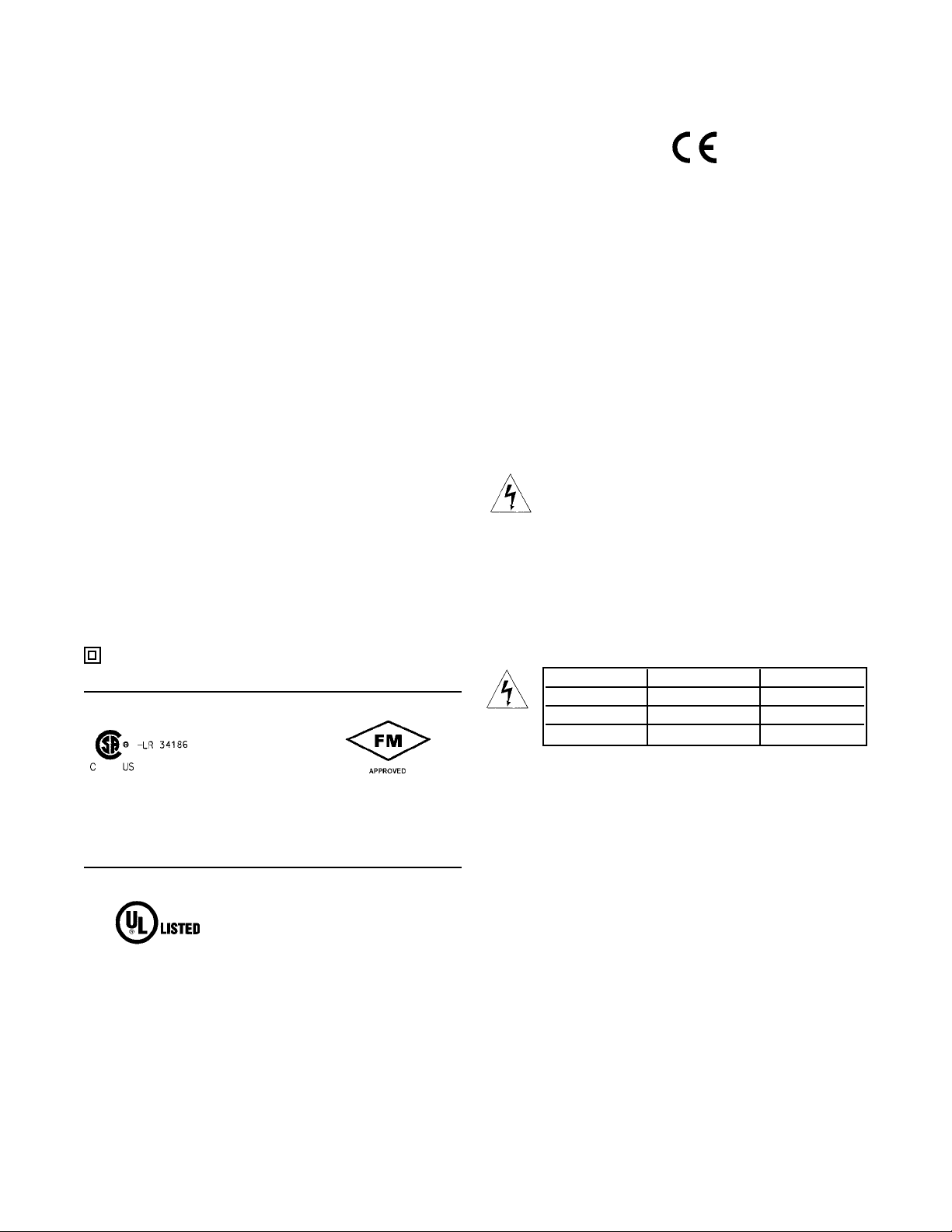
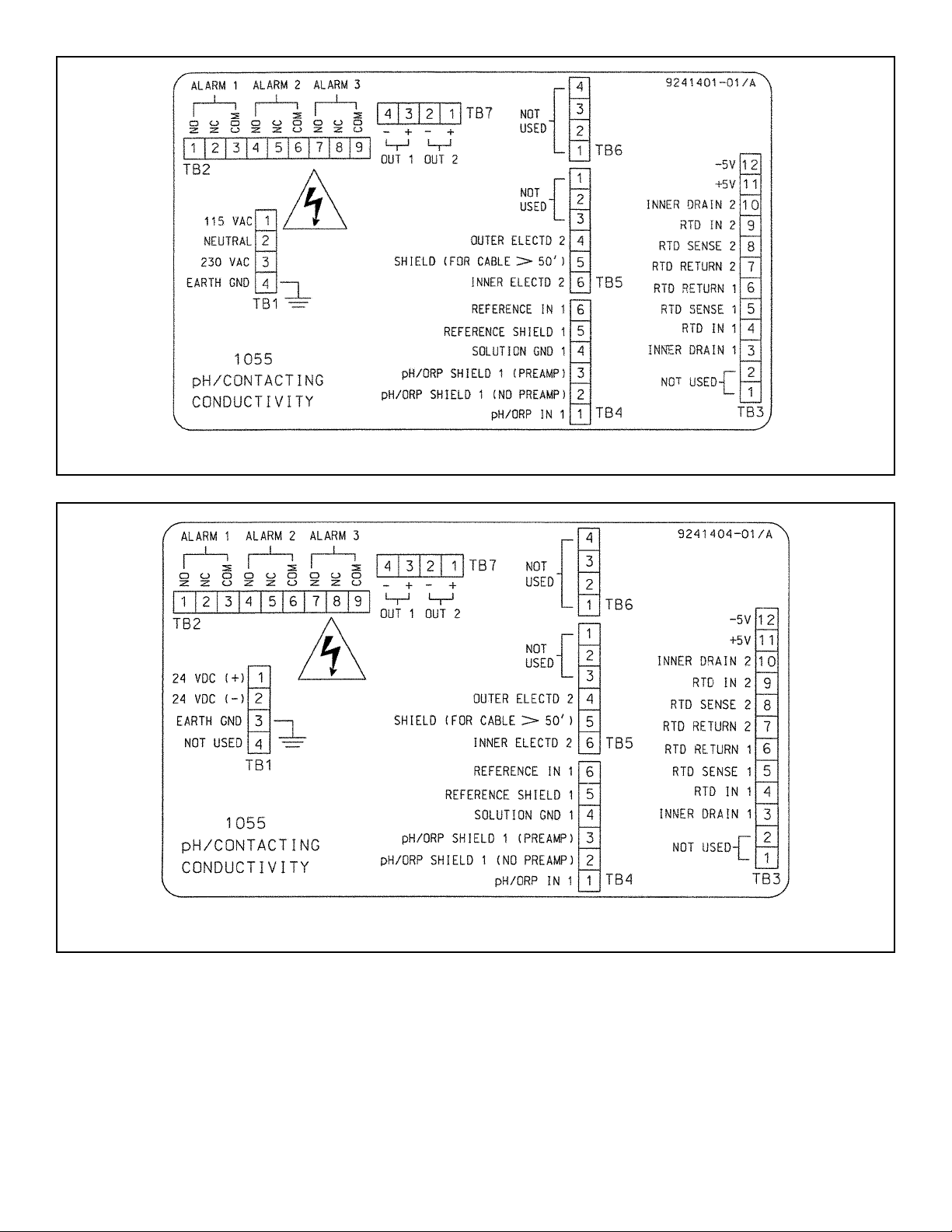
1. Wire sensor(s) to the analyzer. See the drawings below. Refer to the sensor instruction sheet for details. Make
alarm, output, and power connections as shown below.
NOTE
For sensors without solution ground, please use the RC kit included with the instrument.
CONTINUED ON THE FOLLOWING PAGE
Wiring Connections for Solu Comp II Model 1055-01-10 (Panel Mount with 115/230 Vac Power)
Wiring Connections for Solu Comp II Model 1055-02-10 (Panel Mount with 24 Vdc Power)
3
4
CONTINUED ON THE FOLLOWING PAGE
2. Once connections are secured and verified, apply power to the analyzer.
Wiring Connections for Solu Comp II Model 1055-01-11 (Surface/Pipe Mounting with 115/230 Vac Power)
Wiring Connections for Solu Comp II Model 1055-02-11 (Surface/Pipe Mounting with 24 Vdc Power)

4. Choose the desired language. Select >> to show more choices.
5. Choose the number of sensors wired to the analyzer. Press ENTER.
NOTE
If One sensor is chosen, only
S1 (pH/ORP) will be available.
S2 (conductivity) cannot be chosen for single measurement.
6. Select the measurement for sensor 1. Press ENTER.
7. Select the measurement for sensor 2. Press ENTER. This screen will not
appear if one sensor is selected.
8. Enter the cell constant. See label attached to sensor
9. Choose temperature units. Press ENTER.
10. The main display appears. The outputs and alarms are assigned to default values.
11. To change outputs, alarms, and temperature-related settings, go to the Main
Menu and select Program. Follow the prompts. For a guide to the Program
menu, see the menu tree on the following page.
12. To return the analyzer to the default settings, choose Initialize in the Program
menu.
# of sensors?
One
TTwwoo
Temperature in?
*
CC
*
F
S1 Measure?
ppHH
Redox ORP
S2 Measure?
CCoonndd
TDS Resistivity
3. When the analyzer is powered up for the first time, Quick Start screens appear. Using Quick Start is easy.
a. A blinking field shows the position of the cursor.
b. Use the or key to move the cursor left or right. Use the or key to move the cursor up or down or to
increase or decrease the value of a digit. Use the or key to move the decimal point.
c. Press ENTER to store a setting. Press EXIT to leave without storing changes. Pressing EXIT also returns the
display to the previous screen.
EEnngglliisshh
Fran ais
Espa ol >>
&
If there is no cell constant on the label, calculate it
from the equation:
cell const = K
500 + cal const
1000
e
j
Cell Constant?
S1:
11
.0000/cm
5
 Loading...