


Model 1054B pH/ORP
Microprocessor pH/ORP Analyzer
Instruction Manual
PN 51-1054BpH/rev.B
April 2003

WARNING
ELECTRICAL SHOCK HAZARD
Making cable connections to and servicing
this instrument require access to shock
hazard level voltages which can cause
death or serious injury.
Relay contacts made to separate power
sources must be disconnected before
servicing.
Electrical installation must be in accordance with the National Electrical Code
(ANSI/NFPA-70) and/or any other applicable national or local codes.
Unused cable conduit entries must be
securely sealed by non-flammable closures to provide enclosure integrity in
compliance with personal safety and
environmental protection requirements.
For safety and proper performance this
instrument must be connected to a
properly grounded three-wire power
source.
Proper relay use and configuration is
the responsibility of the user.
Do not operate this instrument without
front cover secured. Refer installation,
operation and servicing to qualified personnel.
ESSENTIAL INSTRUCTIONS
READ THIS PAGE BEFORE PROCEED-
ING!
Rosemount Analytical designs, manufactures, and tests its
products to meet many national and international standards.
Because these instruments are sophisticated technical products, you must properly install, use, and maintain them to
ensure they continue to operate within their normal specifications. The following instructions must be adhered to and integrated into your safety program when installing, using, and
maintaining Rosemount Analytical products. Failure to follow
the proper instructions may cause any one of the following situations to occur: Loss of life; personal injury; property damage; damage to this instrument; and warranty invalidation.
• Read all instructions prior to installing, operating, and servicing the product. If this Instruction Manual is not the correct
manual, telephone 1-949-757-8500 and the requested
manual will be provided. Save this Instruction Manual for
future reference.
• If you do not understand any of the instructions, contact
your Rosemount representative for clarification.
• Follow all warnings, cautions, and instructions marked on
and supplied with the product.
• Inform and educate your personnel in the proper installation, operation, and maintenance of the product.
• Install your equipment as specified in the Installation
Instructions of the appropriate Instruction Manual and per
applicable local and national codes. Connect all products to
the proper electrical and pressure sources.
• To ensure proper performance, use qualified personnel to
install, operate, update, program, and maintain the product.
• When replacement parts are required, ensure that qualified
people use replacement parts specified by Rosemount.
Unauthorized parts and procedures can affect the product’s
performance and place the safe operation of your process
at risk. Look alike substitutions may result in fire, electrical
hazards, or improper operation.
• Ensure that all equipment doors are closed and protective
covers are in place, except when maintenance is being performed by qualified persons, to prevent electrical shock and
personal injury.
WARNING
This product is not intended for use in the light industrial, residential or commercial environment, per the instrument’s certification to EN50081-2. Be sure to disconnect all hazardous voltage before opening.
The unused conduit openings need to be sealed with NEMA 4X or IP65 conduit plugs to maintain the ingress protection rating (IP65). No external connection to the instrument of more than 60VDC or 43V peak allowed with the exception of power
and relay terminals. Any violation will impair the safety protection provided.
Emerson Process Management
Rosemount Analytical Inc.
2400 Barranca Parkway
Irvine, CA 92606 USA
Tel: (949) 757-8500
Fax: (949) 474-7250
http://www.RAuniloc.com
© Rosemount Analytical Inc. 2001


MODEL 1054B pH/ORP TABLE OF CONTENTS
MODEL 1054B pH/ORP
MICROPROCESSOR ANALYZER
TABLE OF CONTENTS
Section Title Page
1.0 DESCRIPTION AND SPECIFICATIONS ................................................................ 1
1.1 Features and Applications ....................................................................................... 1
1.2 Physical Specifications-General .............................................................................. 2
1.3 Instrument Specifications......................................................................................... 2
2.0 INSTALLATION....................................................................................................... 3
2.1 General.................................................................................................................... 3
2.2 Unpacking and Inspection ....................................................................................... 3
2.3 Mechanical Installation ............................................................................................ 3
2.4 Electrical Wiring....................................................................................................... 4
3.0 DESCRIPTION OF CONTROLS............................................................................. 14
3.1 Keyboard Functions................................................................................................. 14
4.0 CONFIGURATION................................................................................................... 18
4.1 Configuration ........................................................................................................... 18
4.2 Alarm 1 and 2 ......................................................................................................... 23
4.3 Interval Timer .......................................................................................................... 24
4.4 Temperature ............................................................................................................ 25
4.5 Current Output ........................................................................................................ 25
4.6 pH Electrode Diagnostics ........................................................................................ 26
4.7 Solution Temperature Compensation and Isopotential Point................................... 27
4.8 Defaults.................................................................................................................... 28
4.9 Automatic Buffer Mode ............................................................................................ 29
4.10 Alarm Setpoint ......................................................................................................... 30
4.11 Output Scale Expansion .......................................................................................... 31
4.12 Simulate Current Output .......................................................................................... 32
5.0 START- UP AND CALIBRATION ........................................................................... 33
5.1 Start- Up and Calibration ......................................................................................... 33
5.2 Temperature Calibration .......................................................................................... 33
5.3 Buffer Calibration..................................................................................................... 33
5.4 pH Standardization .................................................................................................. 34
5.5 pH Glass Slope........................................................................................................ 34
5.6 Sensor Maintenance................................................................................................ 34
5.7 Standard ORP Solution ........................................................................................... 35
5.8 ORP Standardization............................................................................................... 36
5.9 Sensor Maintenance................................................................................................ 36
6.0 KEYBOARD SECURITY......................................................................................... 37
6.1 Keyboard Security ................................................................................................... 37
7.0 THEORY OF OPERATION...................................................................................... 38
7.1 Theory of Operation (pH)......................................................................................... 38
7.2 Theory of Operation (ORP)...................................................................................... 38
i

MODEL 1054B pH/ORP TABLE OF CONTENTS
TABLE OF CONTENTS CONT’D.
Section Title Page
8.0 DIAGNOSTICS AND TROUBLESHOOTING ...................................... 39
8.1 Diagnostics ........................................................................................... 39
8.2 Troubleshooting.................................................................................... 42
8.3 Instrument Maintenance ....................................................................... 42
9.0 RETURN OF MATERIALS................................................................... 44
9.1 General................................................................................................. 44
9.2 Warranty Repair.................................................................................... 44
9.3 Non Warranty Repair............................................................................ 44
LIST OF FIGURES
Figure No. Title Page
2-1 Panel Mounting Cutout ......................................................................... 5
2-2 Panel Mounting Tab Installation............................................................ 6
2-3 Wall Mounting J-Box Installation........................................................... 7
2-4 Wall Mounting J-Box Wiring.................................................................. 8
2-5 Pipe Mounting Installation .................................................................... 9
2-6 Electrical Wiring .................................................................................... 10
2-7 Integral Preamp Wiring ......................................................................... 11
2-8 Wall Mount Enclosure (Option -20)....................................................... 12
2-9 Integral Preamp Wiring for Group II Wall Mount Enclosure.................. 13
3-1 LCD Display.......................................................................................... 15
4-1 Menu Items (pH) ................................................................................... 19
4-2 Set Function Menu (ORP) .................................................................... 21
4-3 Interval Timer Example......................................................................... 24
4-4 Alarm Setpoint ...................................................................................... 30
4-5 Output Scale Expansion ....................................................................... 31
4-6 Simulate Current Output ....................................................................... 32
LIST OF TABLES
Table No. Title Page
3-1 Key Description .................................................................................... 16
3-2 Information Mnemonics ........................................................................ 17
3-3 Set Function Mnemonics ...................................................................... 17
4-1 Configuration Work Sheet (pH) ............................................................ 20
4-2 Configuration Worksheet (ORP) ........................................................... 22
4-3 Relay States For Various Analyzer Conditions & Alarm/Default Config. 28
4-4 Buffer Standards................................................................................... 29
5-1 ORP of Saturated Quinhydrone Solution.............................................. 35
8-1 Fault Mnemonics .................................................................................. 39
8-2 RTD Resistance Values........................................................................ 39
8-3 Troubleshooting Guide (pH) ................................................................. 40
8-4 Troubleshooting Guide (ORP) .............................................................. 41
8-5 Sensor Input to Analyzer vs. pH at Four Temperatures........................ 42
8-6 Replacement Parts ............................................................................... 43
8-7 Accessories .......................................................................................... 43
8-8 Ordering Information............................................................................. 43
ii

1
MODEL 1054B pH/ORP SECTION 1.0
DESCRIPTION AND SPECIFICATIONS
SECTION 1.0
DESCRIPTION AND SPECIFICATIONS
• pH ELECTRODE DIAGNOSTICS warn user of the need for calibration or electrode replace-
ment.
• AUTOMATIC BUFFER RECOGNITION with stored buffer-temperature curves
(1054B pH only).
• NEMA 4X (IP65) WEATHERPROOF CORROSION-RESISTANT ENCLOSURE.
• NO BATTERY BACK-UP REQUIRED. Non-volatile EEPROM memory.
• SPECIFIC PROCESS TEMPERATURE COMPENSATION for pH changes due to tempera-
ture (1054B pH only).
1.1 FEATURES AND APPLICATIONS
The Model 1054B Microprocessor Analyzers, with the
appropriate sensor, are designed to continuously measure and control pH, ORP, conductivity, percent concentration, ratio, resistivity, ozone, dissolved oxygen and total
free chlorine in industrial and municipal processes.
The Model 1054B is housed in a NEMA 4X (IP65)
weatherproof corrosion-resistant, flame retardant
enclosure suitable for panel, pipe or wall mounting. All
functions are accessed through the front panel membrane keyboard which features tactile feedback.
Measurement data may be read at any time; however,
settings may be protected against accidental or unauthorized changes by a user selectable security code.
The display indicates the measured value in engineering units as well as temperature, alarm status, hold
output and fault conditions.
The analyzer transmits an isolated current output which
is continuously expandable over the measurement
range for either direct or reverse action. A hold output
function is available for allowing manual control during
routine sensor maintenance. During hold mode the output will be at a preset or last process value.
In the event of one of the following conditions, the
analyzer will drive the output to a preset value in addition to displaying a fault code. The Model 1054B pH’s
continuous self diagnostics alert the user to the following:
With automatic buffer recognition, the analyzer recognizes the buffers, then calculates the electrode slope
using stored pH-temperature curves for ten common
buffers.
Dual alarms are a standard feature on the Model
1054B and are programmable for either high or low
operation. Alarm 2 may be programmed to activate in
event of a failure detected by the continuous diagnostics. Both alarms feature independent setpoints,
adjustable hysteresis and time delay action. A dedicated interval timer with relay is also provided for chemical
or ultrasonic cleaning.
The 1054B pH automatically compensates the pH
reading for process temperature changes. Automatic
or manual temperature compensation is keyboard
selectable. Additional process temperature compensation is available.
The Analyzer includes a 0.7 inch digital display available in LCD or LED format.
The Model 1054B can display the process temperature in °F or °C.
• Broken or cracked electrode
• Worn out or non-immersed
electrode
• Calibration or coated electrode warning
• Faulty slope value (off-line
only)
• Open wiring
• Analyzer electronics failure
• Faulty temperature element or
temperature value

2
MODEL 1054B pH/ORP SECTION 1.0
DESCRIPTION AND SPECIFICATIONS
1.2 PHYSICAL SPECIFICATIONS
Enclosure: Black, ABS, NEMA 4X, IP65,
CSA Enclosure 4
144 X 144 X 192 mm (5.7 X 5.7 X 7.6 in.)
Wall Mount Enclosure: NEMA 4X, Heavy duty
fiberglass, reinforced thermoplastic.
356.4 X 450.1 X 180.2 mm* (14 X 17.7 X 7.1 in.*)
Front Panel: Membrane keyboard with tactile
feedback and user selectable security
Digital Display: LCD, black on grey
Optional, red LED Character Height: 18 mm (0.7 in.)
Electrical Classification:
FM Class I, Div. 2, Group A thru D
28 Vdc relays - 5.0 amps resistive only
150 mA - Groups A & B; 400 mA - Group C ; 540
mA - Group D; Ci = 0; Li = 0
CSA Class I, Div. 2, Group A thru D.
28 Vdc, 110 Vac & 230 Vac relays
5.0 Amps resistive only
Wall Mount Enclosure: General Purpose
Power: 100 - 127 VAC, 50/60 Hz ± 6%, 4.0 W
200 - 253 VAC, 50/60 Hz ± 6%, 4.0 W
Current Output: Isolated, 0-20 mA or 4-20 mA into
600 ohms maximum load at 115/230 Vac
or 550
ohms maximum load at 100/200 Vac, Direct or
Reverse Output Dampening: 0-255 seconds.
Code -20 Wall Mount Enclosure does not meet CE requirements
*Includes latches and mounting feet
The Model 1054B pH Analyzer requires a preamplifier to con-
vert the high impedance pH glass electrode signal to a low
impedance signal. The preamplifier may be located in one of
three areas; in the pH sensor for best performance, in a remote
junction box when process temperatures exceed 80°C (176°F)
in submersion applications, or in the analyzer when the distance
between the pH sensor and the analyzer is 4.5 meters (15 ft) or
less. The result is that the pH signal may then be reliably transmitted from the sensor to the analyzer using standard shielded
4-wire instrument cable.
The Model 1054B pH measures over the full range of 0-14 pH.
The current output may be calibrated to represent any 1 to 14
pH span.
A two-point calibration is made by immersing the sensor in two
different buffer solutions and entering the pH values. When two
buffers are used, the microprocessor automatically calculates
the electrode slope which is used for self-diagnostics. This electrode slope can be read on the display and manually adjusted.
A one point process standardization is also easily accomplished by entering the pH value of a grab sample.
INSTRUMENT SPECIFICATIONS @ 25°C
Measurement Range: 0 to 14 pH
Output Scale Expansion: Zero suppression: up to 13
pH units
Span: Any pH from 1 to 14
Accuracy: ±0.01 pH
Repeatability: ±0.01 pH
Stability: ±0.01 pH/month, non-cumulative
Temperature Coefficient: Input: ±0.003 pH/°C
Output: ±0.006 pH/°C
Temperature Compensation: Pt100 RTD, Automatic
or Manual -15 to 100°C (5 to 212°F)
EMI/RFI: EN61326
LVD: EN61010-1
Ambient Humidity: LED max 95% RH
(LCD max 85% RH @ 50°C)
Ambient Temperature: -10 to 65°C (14 to 149°F)
Alarms: Dual, field selectable High/Low, High/High,
Low/Low Alarm 2 configurable as a fault alarm
Time Delay 0 to 255 seconds
Dual Setpoints, continuously adjustable
Hysteresis is adjustable up to 2 pH units or 25%
full scale for low side/High Alarm and high
side/Low Alarm
Interval Timer: Interval: Minimum 10 minutes
On Counts: 1 to 60
On Duration: 1 to 299 seconds
Off Duration: 1 to 299 seconds
Wait Duration: 1 to 299 seconds
Controls dedicated relay
Relay Contacts: Epoxy Sealed Form A contacts,
SPST, Normally Open.
Resistive Inductive
28 Vdc 5.0 Amps 3.0 Amps
115 Vac 5.0 Amps 3.0 Amps
230 Vac 5.0 Amps 1.5 Amps
Weight/Shipping Weight: 1.1 kg/1.6 kg (2.5 lb/3.5 lb)
The Model 1054B ORP Analyzer measures over the
full range of -1500 mV to +1500 mV full scale user
selectable in either the American convention
(Oxidation Reduction Potential), or the European
convention (Reduction Oxidation-Redox). Although
temperature compensation is not required for ORP
measurements, the process temperature is measured and displayed. Temperature measurement is
made by a Pt 100 RTD located in the sensor assembly.
INSTRUMENT SPECIFICATIONS @ 25°C
Measurement Range: -1500 to +1500 mV
Output Scale Expansion:
Zero suppression: up to ±1500 mV
Span: ±1500 mV
Accuracy: ±1.0 mV
Repeatability: ±1.0 mV
Stability: ±1.0 mV/month, non-cumulative
Temperature Coefficient: Input: ±0.2 mV/°C
Output: ±0.4 mV/°C
Temperature Measurement: -15 to 100°C
(5 to 212°F)
*Model 1054B pH includes programmable temperature correction required
for the presence of ammonia when used in treating high purity water.
1.3 INSTRUMENT SPECIFICATIONS

3
MODEL 1054B pH/ORP SECTION 2.0
INSTALLATION
SECTION 2.0
INSTALLATION
2.1 GENERAL. This analyzer's enclosure is suitable
for outdoor use. However it should be located in an
area where temperature extremes and vibrations are
minimized or absent. Installation must be performed
by a trained technician.
2.2 UNPACKING AND INSPECTION. Inspect the
analyzer for shipping damage. If damaged, notify the
carrier immediately. Confirm that all items shown on
the packing list are present. Notify Rosemount
Analytical if items are missing.
2.3 MECHANICAL INSTALLATION. Select an installation site that is at least one foot from any high voltage conduit, has easy access for operating personnel,
and is not in direct sunlight. Mount the Model 1054B
as follows:
1. Remove the four screws that secure the rear
cover of the enclosure (not required for wall
mounting, options 20 or 21). The latching hardware for panel and pipe mounting is located
inside the rear cover.
2. For standard panel and pipe mounting, remove
the four screws holding the front panel assembly
of the enclosure and carefully pull the front panel
and connected printed circuit boards straight out.
3. Follow the procedure for the appropriate mounting configuration: Section 2.3.1 for panel mounting, Section 2.3.2 for wall mounting, or Section
2.3.3 for pipe mounting.
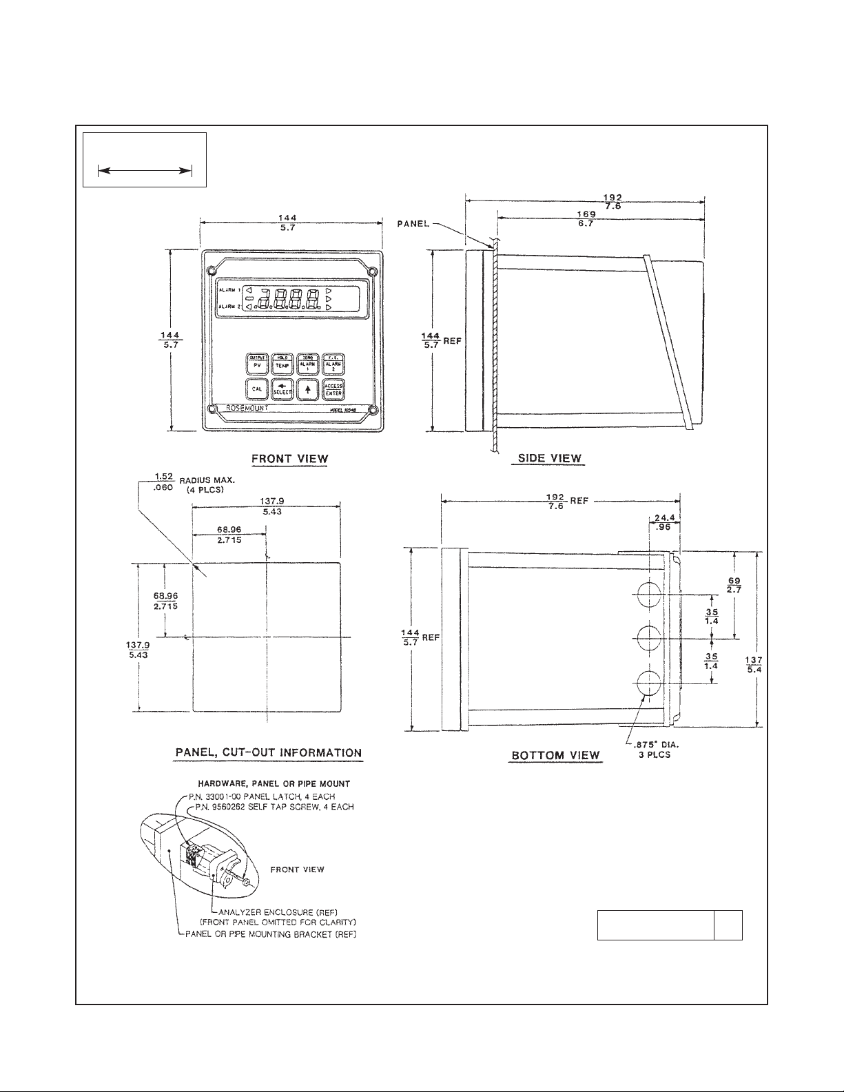
2.3.1 Panel Mounting (Standard). The Model 1054B
is designed to fit into a DIN standard 137.9 mm X
137.9 mm (5.43 in. X 5.43 in.) panel cutout (refer to
Figures 2-1 and 2-2).
1. Prepare the analyzer as described in Section 2.3.
2. Install the mounting latches as shown in Figure 22 (latches are shown oversize for clarity). If the
latches are not installed exactly as shown, they
will not work correctly. The screws provided are
self-tapping. Tap the screw the full depth of the
mounting latch (refer to side view) leaving a gap
greater than the thickness of the cutout panel.
3. Align the latches as shown and insert the analyzer enclosure through the front of the panel cutout.
Tighten the screws for a firm fit. To avoid damaging the mounting latches, do not use excessive
force.
4. Replace the front panel assembly. Circuit boards
must align with the slots on the inside of the enclosure. Replace the door and four front panel screws.
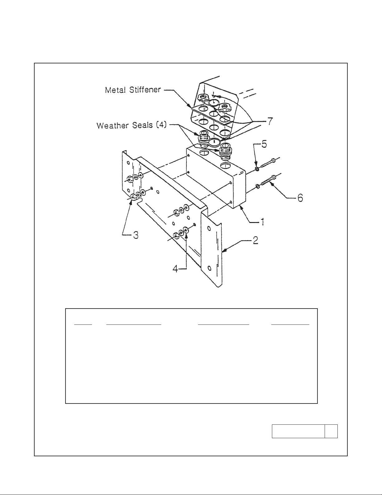
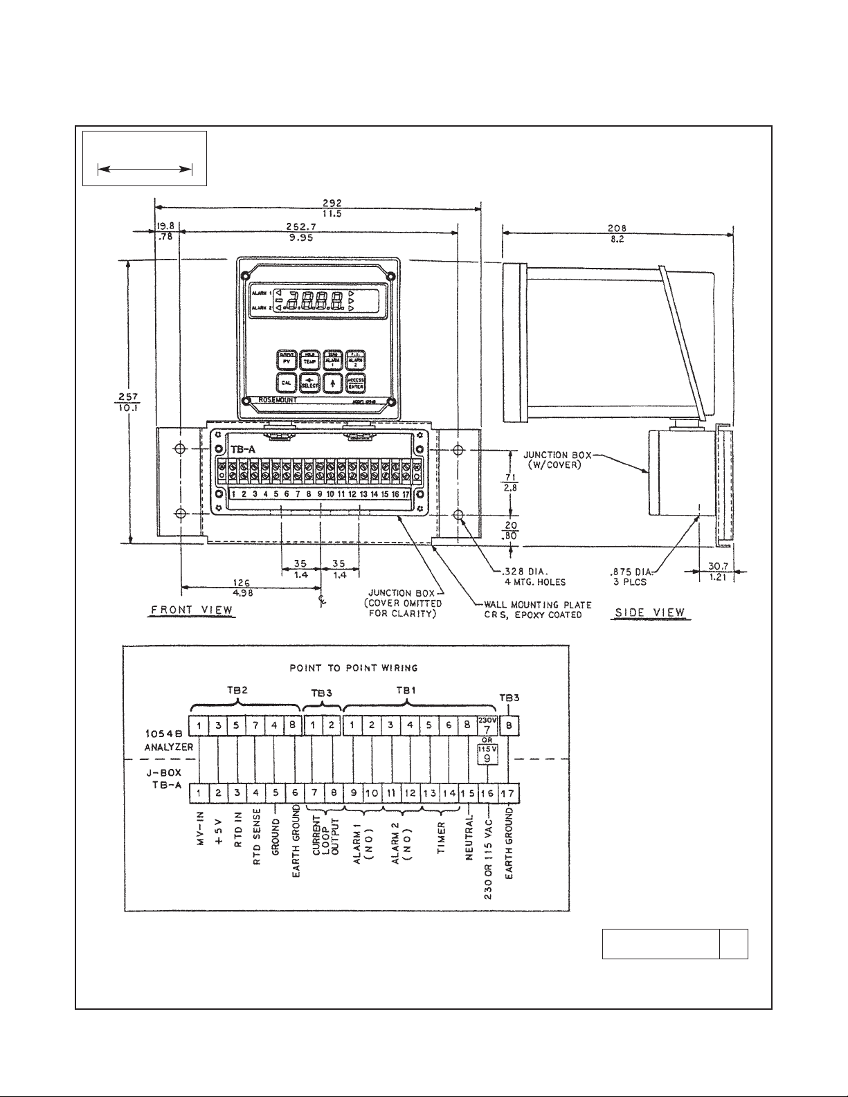
2.3.2 Wall Mounting (P/N 23054-01). Refer to
Figures 2-3 and 2-4. The integral preamp (P/N
23363-00) should not be used with this option.
1. Prepare the analyzer as described in Section 2.3.
2. Mount the junction box and bracket to the analyzer with the hardware provided. All wiring can be
brought to the terminal strip prior to mounting the
analyzer.
3. Place the metal stiffener on the inside of the analyzer and mount the two ¼-inch conduit fittings
using two each weather seals as shown. Mount
NEMA 4X conduit plug (included) into center conduit hole.
4. Mount the analyzer to the junction box using the
1/2-inch conduit fittings.
5. Complete wiring from the 1054B to the junction
box (Figure 2-4).
2.3.3 Pipe Mounting (P/N 23053-00). The 2-inch pipe
mounting bracket includes a metal plate with a cutout
for the 1054B refer to Section 2.3 for mounting the
analyzer into the plate. Mounting details are shown in
Figure 2-5.
2.3.4 Wall Mounting Enclosure (Option -20). Refer
to Figure 2-8. In this configuration, the analyzer is
housed in NEMA 4X heavy duty enclosure and may
be mounted on a wall or handrail. Sufficient clearance
should be provided in front of the enclosure to permit
opening the door, which is hinged on the left side.

NOTE
The user must provide a means to disconnect the main power supply in the form of
circuit breaker or switch. The circuit breaker or the switch must be located in close
proximity to the instrument and identified
as the disconnecting device for the instrument.
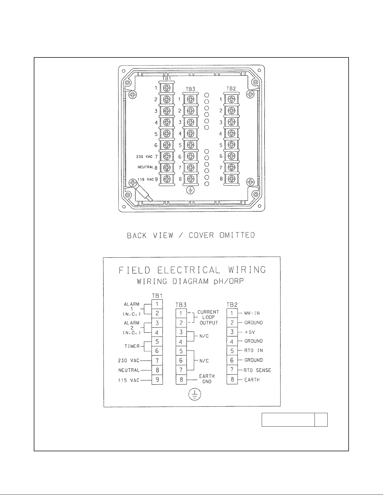
2.4.1 Power Input Wiring. The Model 1054B can be
configured for either 115 VAC or 230 VAC power.
Connect AC power to TB1-7 and -8 (230V), or TB1-8
and -9 (115 VAC) ground to the TB3-8 (refer to
Figure 2-6).
1. AC connections and grounding must be in compliance with UL 508 and/or local electrical codes.
2. The metal stiffener is required to provide support
and proper electrical continuity between conduit
fittings.
3. This type 4/4X enclosure requires a conduit hub
or equivalent that provides watertight connect,
REF UL 508-26.10.
4. Watertight fittings/hubs that comply with the
requirements of UL 514B are to be used.
5. Conduit hubs are to be connected to the conduit
before the hub is connected to the enclosure, REF
UL 508-26.10.
6. If the metal support plate is not used, plastic fittings must be used to prevent structural damage
to the enclosure. Also, appropriate grounding lug
and awg conductor must be used with the plastic
fittings.
2.4.2 Output Wiring. The signal output and alarm
connections are made to terminals 1 through 6 of TB1
and terminals 1 and 2 of TB3 (refer to Figure 2-6).
CAUTION
The sensitivity and stability of the analyzer
will be impaired if the input wiring is not
grounded. DO NOT apply power to the
analyzer until all electrical connections are
verified and secure. The following precautions are a guide using UL 508 as a safeguard for personnel and property.
4
MODEL 1054B pH/ORP SECTION 2.0
INSTALLATION
2.4 ELECTRICAL WIRING. The Model 1054B has
three conduit openings in the bottom rear of the
analyzer housing which will accommodate
1/2-inch
conduit fittings. From a back view, the conduit opening on the left is for timer, alarm, and AC connections; the center is for signal output and the opening
on the right is for sensor wiring. AC power wiring
should be 14 gauge or greater.
The wall mount enclosure has three 3/4-inch conduit
openings, two with 3/4-inch fittings and one with a
NEMA 4X conduit plug. From the front view the
conduit opening on the left is for sensor wiring; the
center is for signal output, and the right is for timer,
alarm and AC power supply connections. Sensor
wiring should always be run in a separate conduit
from power wiring.
NOTE
Wall mount: use opening on the left for sensor
wiring (refer to Figure 2-4 for wiring).
NOTE
PN 23363-00 (integral preamplifier). Refer to
Figure 2-7 for installation and wiring. PN 2350800 (integral preamp is for wall mount enclosure). Refer to Figure 2-9.
NOTE
For maximum EMI/RFI protection the output
cable should be shielded and enclosed in an
earth grounded, rigid metal conduit. When
wiring directly to the instrument connect the
output cable‘s outer shield to the transmitter’s
earth ground via terminal 8 on TB3, Fig. 2-6.
When wiring to the wall mounting junction box
connect the output cable’s outer shield to earth
ground via terminal 6 of TB-A, Fig. 2-4.
The sensor cable should also be shielded.
When wiring directly to the instrument connect
the sensor cable’s outer shield to the transmitter’s earth ground via terminal 8 of TB2, Fig. 2-
6. If the sensor cable’s outer shield is braid an
appropriate metal cable gland fitting may be
used to connect the braid to earth ground via
the instrument case. When wiring to the wall
mounting junction box connect the cable’s
outer shield to earth ground via terminal 6 of
TB-A, Fig. 2-4.
5
FIGURE 2-1. Panel Mounting Cutout
MODEL 1054B pH/ORP SECTION 2.0
INSTALLATION
WHEN INCH AND METRIC DIMS
ARE GIVEN
MILLIMETER
INCH
DWG. NO. REV.
41054B01 B

6
MODEL 1054B pH/ORP SECTION 2.0
INSTALLATION
FIGURE 2-2. Panel Mounting Tab Installation
DWG. NO. REV.
41054A26 A
7
MODEL 1054B pH/ORP SECTION 2.0
INSTALLATION
FIGURE 2-3. Wall Mounting J-Box Installation
DWG. NO. REV.
41054A27 A
ITEM PART NUMBER DESCRIPTION QUANTITY
1 23058-01 S Assy, J-Box 1
2 33030-00 Bracket, wall mtg 1
3 9900600 Nut, 6-32 Hex 4
4 9910600 Washer, Flat #6 4
5 9910610 Washer, Lock Int. #6 8
6 9600612 Screw, 6-32 X .75 4
7 9510048 Seal, Weathertight 1
MODEL 1054B pH/ORP SECTION 2.0
INSTALLATION
8
FIGURE 2-4. Wall Mounting J-Box Wiring
DWG. NO. REV.
41054B13 B
WHEN INCH AND METRIC DIMS
ARE GIVEN
MILLIMETER
INCH

MODEL 1054B pH/ORP SECTION 2.0
INSTALLATION
9
FIGURE 2-5. Pipe Mounting Installation
WHEN INCH AND METRIC DIMS
ARE GIVEN
MILLIMETER
INCH
DWG. NO. REV.
41054B02 C
10
MODEL 1054B pH/ORP SECTION 2.0
INSTALLATION
FIGURE 2-6. Electrical Wiring
DWG. NO. REV.
41054B03 C
 Loading...