

Legacy Manual: 975MR Multi-Spectrum Infrared Flame Detector | Rosemount
Table of contents
 Loading...
Rosemount Legacy Manual: 975MR Multi-Spectrum Infrared Flame Detector | Rosemount Manuals & Guides

Rosemount™ 975MR
Legacy
Multi-Spectrum Infrared Flame Detector
Reference Manual
00809-0100-4975, Rev DD
November 2021

Legal notice
Legacy
The device described in this document is the property of Emerson.
No part of the hardware, software, or documentation may be reproduced, transmitted, transcribed, stored in a retrieval system,
or translated into any language or computer language, in any form or by any means, without prior written permission from
Emerson.
While great efforts have been made to ensure the accuracy and clarity of this document, Emerson assumes no liability resulting
from any omissions in this document or from misuse of the information obtained herein. The information in this document has
been carefully checked and is believed to be entirely reliable with all of the necessary information included. Emerson reserves the
right to make changes to any products described herein to improve reliability, function, or design and reserves the right to revise
this document and make changes from time to time in content hereof with no obligation to notify any persons of revisions or
changes. Emerson does not assume any liability arising out of the application or any use of any product or circuit described herein;
neither does it convey license under its patent rights or the rights of others.
WARNING
All individuals who have or will have responsibility for using, maintaining, or servicing this product must read this document
carefully.
WARNING
Physical access
Unauthorized personnel may potentially cause significant damage to and/or misconfiguration of end users’ equipment. This could
be intentional or unintentional and needs to be protected against.
Physical security is an important part of any security program and fundamental to protecting your system. Restrict physical access
by unauthorized personnel to protect end users’ assets. This is true for all systems used within the facility.
CAUTION
Equipment damage
This device is not field repairable due to the meticulous alignment and calibration of the sensors and the respective circuits.
Modifying or repairing the internal circuits may impair the system's performance and void the Emerson product warranty.
Do not attempt to modify or repair the internal circuits or change their settings.
Warranty
1. Limited Warranty . Subject to the limitations contained in Section 2 (Limitation of Remedy and Liability) herein, Seller
warrants that (a) the licensed firmware embodied in the Goods will execute the programming instructions provided by
Seller; (b) that the Goods manufactured by Seller will be free from defects in materials or workmanship under normal use
and care; and (c) Services will be performed by trained personnel using proper equipment and instrumentation for the
particular Service provided. The foregoing warranties will apply until the expiration of the applicable warranty period.
Products purchased by Seller from a third party for resale to Buyer (Resale Products) shall carry only the warranty
extended by the original manufacturer. Buyer agrees that Seller has no liability for Resale Products beyond making a
reasonable commercial effort to arrange for procurement and shipping of the Resale Products. If Buyer discovers any
warranty defects and notifies Seller thereof in writing during the applicable warranty period, Seller shall, at its option, (i)
correct any errors that are found by Seller in the firmware or Services; (ii) repair or replace FOB point of manufacture that
portion of the Goods found by Seller to be defective; or (iii) refund the purchase price of the defective portion of the
Goods/Services. All replacements or repairs necessitated by inadequate maintenance; normal wear and usage; unsuitable
power sources or environmental conditions; accident; misuse; improper installation; modification; repair; use of
unauthorized replacement parts; storage or handling; or any other cause not the fault of Seller, are not covered by this
limited warranty and shall be replaced or repaired at Buyer's sole expense, and Seller shall not be obligated to pay any
costs or charges incurred by Buyer or any other party except as may be agreed upon in writing in advance by Seller. All
costs of dismantling, reinstallation, freight, and the time and expenses of Seller's personnel and representatives for site
travel and diagnosis under this limited warranty clause shall be borne by Buyer unless accepted in writing by Seller. Goods
repaired and parts replaced by Seller during the warranty period shall be in warranty for the remainder of the original
warranty period or 90 days, whichever is longer. This limited warranty is the only warranty made by Seller and can be
amended only in a writing signed by an authorized representative of Seller. The limited warranty herein ceases to be
effective if Buyer fails to operate and use the Goods sold hereunder in a safe and reasonable manner and in accordance
2

with any written instructions from the manufacturers. THE WARRANTIES AND REMEDIES SET FORTH ABOVE ARE
Legacy
EXCLUSIVE. THERE ARE NO REPRESENTATIONS OR WARRANTIES OF ANY KIND, EXPRESSED OR IMPLIED, AS TO
MERCHANTABILITY, FITNESS FOR PARTICULAR PURPOSE, OR ANY OTHER MATTER WITH RESPECT TO ANY OF THE GOODS
OR SERVICES.
2. Limitation of Remedy and Liability SELLER SHALL NOT BE LIABLE FOR DAMAGES CAUSED BY DELAY IN PERFORMANCE. THE
REMEDIES OF BUYER SET FORTH IN THE AGREEMENT ARE EXCLUSIVE. IN NO EVENT, REGARDLESS OF THE FORM OF THE
CLAIM OR CAUSE OF ACTION (WHETHER BASED IN CONTRACT INFRINGEMENT, NEGLIGENCE, STRICT LIABILITY, OTHER
TORT, OR OTHERWISE), SHALL SELLER'S LIABILITY TO BUYER AND/OR BUYER'S CUSTOMERS EXCEED THE PRICE TO BUYER
OF THE SPECIFIC GOODS MANUFACTURED OR SERVICES PROVIDED BY SELLER GIVING RISE TO THE CLAIM OR CAUSE OF
ACTION. BUYER AGREES THAT IN NO EVENT SHALL SELLER'S LIABILITY TO BUYER AND/OR BUYER'S CUSTOMERS EXTEND
TO INCLUDE INCIDENTAL, CONSEQUENTIAL, OR PUNITIVE DAMAGES. THE TERM "CONSEQUENTIAL DAMAGES" SHALL
INCLUDE, BUT NOT BE LIMITED TO, LOSS OF ANTICIPATED PROFITS, REVENUE OR USE AND COSTS INCURRED INCLUDING
WITHOUT LIMITATION FOR CAPITAL, FUEL AND POWER, AND CLAIMS OF BUYER'S CUSTOMERS.
Technical support
To get technical support for this product, contact your local Rosemount representative or the Rosemount Technical Support
department at +1 866 347 3427 or safety.csc@emerson.com
Return of material
To expedite the repair and return of this product, proper communication between the customer and the factory is important.
Before returning a product for repair, call +1 866 347 3427 or email safety.csc@emerson.com for a return material authorization
(RMA) number.
On the return of equipment, provide the following information:
1. RMA number provided to you by Emerson
2. Company name and contact information
3. Purchase order from your company authorizing repairs of request for quote
Ship all equipment prepaid to:
Emerson Automation Solutions
Measurement Solutions
6021 Innovation Blvd
Shakopee, MN 55379
Mark all packages with "Return for Repair" and include the RMA number.
Pack items to protect them from damage and use anti-static bags or aluminum-backed cardboard as protection from electrostatic
damage.
Ship all equipment prepaid. Emerson will not accept collect shipments.
Abbreviations and acronyms
Abbreviation or acronym Definition
ATEX Atmospheric explosives
AWG American wire gauge
BIT Built-in test
EMC Electromagnetic compatibility
EOL End of line
FOV Field of view
®
HART
IAD Immune at any distance
IECEx International Electrotechnical Commission Explosion
IPA Isopropyl alcohol
Highway addressable remote transducer - communication protocol
3

Abbreviation or acronym Definition
Legacy
IR Infrared
JP5 Type of jet fuel
Latching Refers to relays remaining in the ON state even after the ON condition has been
LED Light emitting diode
LPG Liquified petroleum gas
mA Milliamps (0.001 amps)
®
Modbus
N.C. Normally closed
N.O. Normally open
N/A Not applicable
NFPA National Fire Protection Association
NPT National pipe thread
RS485 Communication protocol allowing bi-directional communication
PN Part number
SIL Safety integrity level
UNC Unified coarse thread
Vac Volts alternating current
Vdc Volts direct current
removed.
Master-slave messaging structure
4

Reference Manual Contents
Legacy
00809-0100-4975
November 2021
Contents
Chapter 1 Introduction.............................................................................................................. 7
1.1 Overview..................................................................................................................................... 7
1.2 Ordering information...................................................................................................................8
1.3 Features and benefits.................................................................................................................11
1.4 Principles of operation............................................................................................................... 12
1.5 Performance considerations...................................................................................................... 15
1.6 Internal detector tests............................................................................................................... 23
Chapter 2 Installing the detector..............................................................................................27
2.1 General guidelines.....................................................................................................................27
2.2 Unpack...................................................................................................................................... 28
2.3 Required tools........................................................................................................................... 28
2.4 Certification instructions........................................................................................................... 29
2.5 Installing cables......................................................................................................................... 30
2.6 Installing the tilt mount (PN 00975-9000-0001)........................................................................ 30
2.7 Connect the detector.................................................................................................................34
2.8 Configure the detector.............................................................................................................. 37
Chapter 3 Operating the detector............................................................................................ 41
3.1 Power up................................................................................................................................... 41
3.2 Safety precautions.....................................................................................................................41
3.3 Testing procedures....................................................................................................................42
Chapter 4 Maintenance and troubleshooting........................................................................... 45
4.1 Maintenance..............................................................................................................................45
4.2 Troubleshooting........................................................................................................................46
Appendix A Specifications and reference data.............................................................................49
Appendix B Wiring instructions.................................................................................................. 55
Appendix C RS-485 communication network.............................................................................. 63
Appendix D Accessories.............................................................................................................. 65
A.1 Technical specifications.............................................................................................................49
A.2 Electrical specifications..............................................................................................................49
A.3 Outputs.....................................................................................................................................50
A.4 Mechanical specifications..........................................................................................................52
A.5 Environmental specifications.....................................................................................................52
B.1 General instructions for electrical wiring....................................................................................55
B.2 Typical wiring configurations.....................................................................................................57
D.1 Flame simulator........................................................................................................................ 65
Rosemount 975MR 5

Contents Reference Manual
Legacy
November 2021 00809-0100-4975
D.2 Tilt mount: PN 00975-9000-0001..............................................................................................70
D.3 Duct mount...............................................................................................................................70
D.4 Weather cover: PN 00975-9000-0003.......................................................................................71
D.5 Air shield: PN 00975-9000-0005................................................................................................72
Appendix E SIL-2 features........................................................................................................... 73
E.1 Safety relevant parameters........................................................................................................ 73
E.2 Guidelines for configuring, installing, operating, and service..................................................... 73
Appendix F End of line resistor....................................................................................................77
6 Emerson.com/Rosemount

Reference Manual Introduction
Legacy
00809-0100-4975 November 2021
1 Introduction
1.1 Overview
The Rosemount Rosemount 975MR Multi-spectrum Flame Detector uses improved multispectrum infrared technology to provide state-of-the-art fire protection. The detector
uses patented digital signal processing to analyze the spectral and dynamic characteristics
of the measured infrared radiation to identify fire events with exceptional sensitivity and
extreme immunity to fire alarms.
All Rosemount 975 series detectors include a heated optical window for improved
performance in icing, snow, and condensation conditions.
The operator can easily adapt detection performance to all environments, applications,
and requirements by changing the detector's configuration parameters. Adjusting these
parameters, as well as performing other maintenance and monitoring tasks, is possible by
means of RS-485 based Modbus® communication or HART® communication (in models
with 0-20 mA output).
The detector enclosure is ATEX certified Exd flameproof with an integral, segregated, rear,
Exe terminal compartment (avoiding exposure of the sensors and electronics to
surrounding environment). Hence the combined approval:
Ex II 2G D
Ex db eb op is IIC T4 G
Ex tb op is IIIC T96 °C Db
(-55 °C ≤ Ta ≤ +75 °C)
or
Ex II 2G D
Ex db eb op is IIC T4 Gb
Ex tb op is IIIC T106 °C Db
(-55 °C ≤ Ta ≤ +85 °C)
The flame detector is designed to operate as a stand-alone unit directly connected to an
alarm system or an automatic fire extinguishing system. The detector can also be part of a
more complex system where many detectors and other devices are integrated through a
common control unit.
Rosemount 975MR 7
Introduction Reference Manual
Legacy
November 2021 00809-0100-4975
1.2 Ordering information
The Rosemount 975MR is provided in various configurations depending on:
• Output configurations
• Temperature
• Housing style
• Product certifications
The configuration detail is included in the product part
number on the product label and takes the form:
Rosemount 975MR-XXXXXXX, where XXXXXXX defines the
model according to the above requirements.
To modify the default or pre-ordered configuration and
perform maintenance tasks, please refer to the following
manuals: Rosemount 975 Flame Detector HART
Communication Manual (00809-0200-4975) or WinHost
Configuration and Diagnostic Software for Rosemount 975
Flame Detectors (00809-0300-4975).
CONFIGURE > VIEW PRODUCT >
Typical model number: 975MR1A6A1A1
The starred offerings (★) represent the most common
options and should be selected for best delivery. The nonstarred offerings are subject to additional delivery lead
time.
1.2.1 Product description
Code Description
975 975 flame detector ★
1.2.2 Technology
Code Description
MR Multi-spectrum infrared ★
HR Multi-spectrum infrared hydrogen ★
UF Ultra fast ultraviolet infrared ★
UR Ultraviolet infrared ★
8 Emerson.com/Rosemount

Reference Manual Introduction
Legacy
00809-0100-4975 November 2021
1.2.3 Output configuration
Code Outputs Fault relay Alarm relay Auxiliary relay Current type
1A Analog/HART®/
RS-485/relays
(fault, alarm)
2A Analog/HART/
RS-485/relays
(fault, alarm)
3A Analog/HART/
RS-485/relays
(fault, alarm)
1R RS-485/relays
(fault, alarm,
auxiliary)
2R RS-485/relays
(fault, alarm,
auxiliary)
Normally closed Normally open N/A Sink ★
Normally closed Normally open,
normally closed
Normally open Normally open,
normally closed
Normally closed Normally open Normally open N/A ★
Normally open Normally open Normally open N/A ★
N/A Source ★
N/A Source ★
1.2.4 Housing style
Code Material Conduit entry
(1)
6A
8A
Aluminum ¾-in. national pipe thread (NPT) ★
(1)
Aluminum M25 ★
6S Stainless steel ¾-in. NPT ★
8S Stainless steel M25 ★
(1) Aluminum housing is not available in FM/CSA product certification.
1.2.5 Temperature
Code Description
1 167 °F (75 °C) ★
2 185 °F (85 °C) ★
1.2.6 Product certifications
Code Description
A1 ATEX and IECEx flameproof ★
A2 FM and CSA flameproof ★
E2 InMetro flameproof ★
EM Technical Regulations Customs Union (EAC) flameproof ★
Rosemount 975MR 9

Introduction Reference Manual
Legacy
November 2021 00809-0100-4975
1.2.7 Spare parts and accessories
Part number Description
00975-9000-0001 Tilt mount ★
00975-9000-0002 Duct mount ★
00975-9000-0003 Weather cover (plastic) ★
00975-9000-0004 Weather cover (stainless steel) ★
00975-9000-0005 Air shield ★
00975-9000-0007 2-in. (50.8 mm) pipe mount ★
00975-9000-0008 3-in. (76.2 mm) pipe mount ★
00975-9000-0009 Flame simulator kit (for Rosemount 975MR) ★
00975-9000-0011 USB RS-485 harness kit ★
00975-9000-0012 Spare battery pack for use with flame simulator ★
00975-9000-0014 4-in. (101.6 mm) pipe mount ★
00975-9000-0015 Spare battery charger for use with flame simulator ★
1.2.8 Output configurations
Output
configuration
1A Power Manual built-
2A Power Manual built-
3A Power Manual built-
1R Power Manual built-
2R Power Manual built-
Connections provided
in test
in test
in test
in test
in test
Fault relay
N.C.
Fault relay
N.C.
Fault relay
N.O.
Fault relay
N.C.
Fault relay
N.O.
Alarm relay
N.O.
Alarm relay,
N.O., N.C.
Alarm relay
N.O., N.C.
Alarm relay
N.O.
Alarm relay
N.O.
NOTICE
Output configuration 1A is default. You can change the mA sink output to source type,
with a link between terminals 1 and 8. You cannot change any other output configurations
on site.
0-20 mA sink RS-485 HART
0-20 mA
source
0-20 mA
source
Auxiliary
N.O.
Auxiliary
N.O.
RS-485 HART
RS-485 HART
RS-485 N/A
RS-485 N/A
®
For example, product number Rosemount 975MR3A8S2A1 has the following options:
• Output configuration: 3A (analog/HART/RS-485/relays, fault N.O., alarm N.O./N.C.,
source)
• Housing style: 8S (stainless steel - M25 conduit entry)
10 Emerson.com/Rosemount

Reference Manual Introduction
Legacy
00809-0100-4975 November 2021
• Temperature: 2 (185 °F [85 °C])
• Approvals: A1 (ATEX and IECEx flameproof)
NOTICE
Check your specific part numbers against the information in Checking the product type.
1.3 Features and benefits
The flame detector has the following features and benefits.
• Detection range: Up to 215 ft. (65 m) for a 1 ft.2 (0.1 m2) n-heptane fire.
• Ultra high immunity to false alarms. See Table 1-3.
• Advanced digital processing of the dynamic characteristics of fire: flickering, threshold,
correlation, and ratio.
• Multi infrared channels: between two and five microns.
• Field programmable sensitivity: four ranges to avoid zone crossover.
• Built-in-test (BIT): manual and automatic (see Built-in test (BIT)).
• Heated window: prevents effects of icing, snow, and condensation.
• Electrical interface:
— Dry contact relays
— Communication network RS-485
— 0-20 mA output
• HART® protocol: communication protocol (see HART® protocol).
• Exde: integral junction box for easy wiring.
• SIL-2: TÜV approved.
• Hazardous area certification: ATEX, IECEx, FM, and CSA.
• Functionality approval:
— EN54-10 approved by VdS
— FM approved per FM3260
• Accessories are approved as part of ATEX and IECEx approval.
Rosemount 975MR 11

Introduction Reference Manual
Legacy
November 2021 00809-0100-4975
1.4 Principles of operation
1.4.1 Hydrocarbon fire detection
The Rosemount 975MR uses four infrared sensors, each sensitive to its own wavelength
range. Two of the sensors are sensitive to wavelengths within the emission peak of hot
CO2. The other two sensors are sensitive to wavelengths above and below this peak.
In the event of fire, the signal measured in the first sensor is significantly higher than those
measured in the other two sensors. In order to issue a fire alarm, the detector requires that
this occurs, as well as other conditions (for example, radiation is flickering in frequencies
typical of flames). If exposed to non-fire radiation sources, the specific conditions required
do not occur, and the detector does not react.
1.4.2 Heated optics
The flame detector uses heated optics. The heater increases the temperature of the
optical surface by 5 to 8 °F (3 to 5 °C) above the ambient temperature to improve
performance in icing, condensation, and snow conditions.
The heated optics can be set to one of the following:
• Off, not operating.
• On continuously.
• Automatic, per temperature change (default): the operator can define the start
temperature below which the window is heated. The default is 41 °F (5 °C). The
operator can define this temperature between 32 °F (0 °C) and 122 °F (50 °C). The
heating stops when the temperature is 27 °F (15 °C) above the start temperature.
For more information, see Configure the detector.
1.4.3 HART® protocol
The flame detector uses the HART protocol.
HART communication is a bi-directional industrial field communication protocol used to
communicate between intelligent field instruments and host systems. HART is the global
standard for smart process instrumentation, and the majority of smart field devices
installed in plants worldwide are HART-enabled. HART is available in output configurations
1A, 2A, and 3A (see Output configuration).
Through the HART connection, you can do the following:
• Detector setup
• Detector troubleshooting
• Detector health and status
For more details, refer to Rosemount 975 HART Communication Manual
(00809-0200-4975).
12 Emerson.com/Rosemount

Reference Manual Introduction
Legacy
00809-0100-4975 November 2021
1.4.4 RS-485 Modbus
For more advanced communications, the flame detector has an RS-485 Modbuscompatible output that provides data communication from a network (up to 247
detectors) to a host computer or universal controller for central monitoring. This feature
allows for reduced installation costs, easy maintenance, and local or remote diagnostic
tools.
®
1.4.5 Product certifications
The flame detector has the following certifications:
• ATEX, IECEx
• FM, CSA
• SIL-2 (TÜV)
• EN54-10
• InMetro (UL)
• TR CU/EAC
ATEX, IECEx
The flame detector is certified to:
ATEX per SIRA 15ATEX1364X and IECEx per IECEx SIR 15.0138X.
Ex II 2G D
Ex db eb op is IIC T4 Gb
Ex tb op is IIIC T96 °C Db
(-55 °C ≤ Ta ≤ +75 °C)
or
Ex II 2G D
Ex db eb op is IIC T4 Gb
Ex tb op is IIIC T106 °C Db
(-55 °C ≤ Ta ≤ +85 °C)
The accessories: tilt mount (PN 00975-9000-0001), weather cover (PN 00975-9000-0003
[plastic] and PN 00975-9000-0004 [stainless steel]), duct mount (PN 00975-9000-0002),
and air shield (PN 00975-9000-0005), are included in the approval.
This product is available to use in hazardous zones 1 and 2 with IIC gas group vapors
present and zones 21 and 22 with IIIC dust type present.
FM, CSA
The flame detector is certified to FM and CSA explosion proof and functionality per
FM3260.
• Class I, Division 1, Groups B, C, and D, T5 Ta = 85 °C.
Rosemount 975MR 13

Introduction Reference Manual
Legacy
November 2021 00809-0100-4975
• Dust ignition proof - Class II/III Division 1, Groups E, F, and G.
• Ingress protection - IP67, IP66, NEMA 250 Type 6P
• Fuel test response including: gasoline, n-heptane, diesel, JP5, kerosene, ethyl, alcohol
95 percent, IPA, methanol, methane, LPG, polypropylene, and paper.
• For more details, see FM Report Project ID3029553 and CSA Report No. 2451134.
SIL-2 (TÜV)
The flame detector is certified to SIL-2 requirement per IEC 61508A, Chapter 3.5.12.
The alert condition according to SIL-2 can be implemented by:
• Alert signal via 0-20 mA current loop
or
• Alert signal via alarm relay and fault relay
For more details and guidelines for configuring, installing, operating, and service, see SIL-2
features and TUV Report No. 968/FSP 1223.
EN54-10
The flame detector is approved per EN54-10 and CPD.
• The detector is listed as Class 1 for sensitivity settings 15, 30, 45, and 60.
• The detector has been tested and approved per EN54-10 Vds.
• This test includes functional test, environmental test, EMI/EMC test, and software
check.
• For more details, see Vds Report Number BMA 150190-AU01+BZA02-PB01.
InMetro (UL)
The flame detector is in compliance with the following standards as of May 18, 2010:
• ABNT NBR IEC 60079-0
• ABNT NBRIEC 60079-1
• ABNT NBR IEC 60079-7
• ABNT NBR IEC 60079-18
• ABNT NBR IEC 60079-31
• INMETRO decree No. 179
For further details, see the Certificate of Compliance No. UL-BR 16.065XX.
TR CU/EAC
The flame detector is in compliance with the standard TR CU 012/2011 per:
1Ex db eb op is IIC T4 Gb X
Ex tb op is IIIC T96 °C Db X
14 Emerson.com/Rosemount

Reference Manual Introduction
Legacy
00809-0100-4975 November 2021
-55 °C ≤ Ta ≤ +75 °C
or
1Ex db eb op is IIC T4 Gb X
Ex tb op is IIIC T106 °C Db X
-55 °C ≤ Ta ≤ +85 °C
For more details, see TR CU certificate No. TC RU C-US MЮ 62.B05535.
1.5 Performance considerations
1.5.1 Detection sensitivity
Detection sensitivity is the maximum distance at which the detector reliably detects a
specific size of fire and typical type of fuel (standard fire).
Standard fire
Defined as 1 ft.2 (0.1 m2) n-heptane pan fire with maximum wind speed of 6.5 ft./sec
(2 m/sec).
Sensitivity ranges
The detector has four user-selectable sensitivity ranges. For each range, there are two
response levels:
• Warning (Pre-alarm)
• Alarm
The detection distance for the Warning level is approximately 10 percent higher than the
Alarm distance.
Alarm response times for a standard fire at a specified range are shown in Table 1-1.
Table 1-1: Sensitivity Range Levels
Level Response time (sec) Sensitivity range - ft. (m) (for
1 3 50 (15)
2 default 5 100 (30)
3 8 150 (45)
4 10 215 (65)
1 ft.2 (0.1 m2) n-heptane pan
fire)
For some typical ambient conditions, the Zeta parameter as defined in NFPA 72 for the
detector is 0.005 (1/meter).
Note
Zeta parameters may vary significantly with changes in temperature, air pressure,
humidity, visibility conditions, etc.
Rosemount 975MR 15

Introduction Reference Manual
Legacy
November 2021 00809-0100-4975
Other fuels
The detector reacts to other types of fire as follows:
• The baseline fire refers to n-heptane 1 ft.2 (0.1 m2) and is defined as 100 percent
sensitivity.
• For fuel fire: standard pan fire size: 1 ft.2 (0.1 m2)
• For gas flame: 30 in. (0.75 m) high, 10 in. (0.25 m) wide plume fire
• Maximum response time: 10 sec.
Table 1-2: Fuel Sensitivity Ranges
Type of fuel Percent of max. distance at each sensitivity range Max. distance
(ft. / m)
Gasoline 100% 215 / 65
n-Heptane 100% 215 / 65
JP5 70% 150 / 45
Kerosene 70% 150 / 45
Diesel fuel 70% 150 / 45
Ethanol 95% 60% 135 / 40
IPA 60% 135 / 40
Methanol 55% 115 / 35
(1)
(1)
70% 150 / 45
70% 150 / 45
Methane
LPG
Paper 38% 82 / 25
Polypropylene 55% 115 / 35
(1) 30 in. (0.75 m) high, 10 in. (0.25 m) wide plume fire
16 Emerson.com/Rosemount
Reference Manual Introduction
Legacy
00809-0100-4975 November 2021
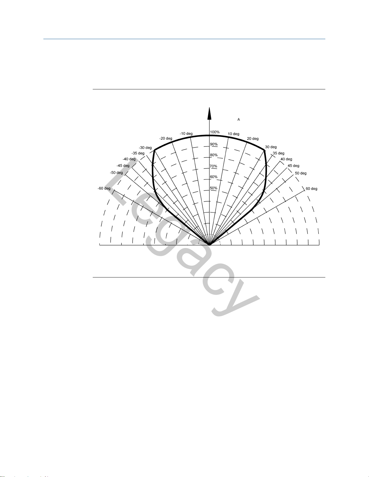
1.5.2 Field of view
For Rosemount 975MR, 975UF, and 975UR
Figure 1-1: Horizontal Field of View
A. Relative range
Horizontal: 100 °
Rosemount 975MR 17
Introduction Reference Manual
Legacy
November 2021 00809-0100-4975
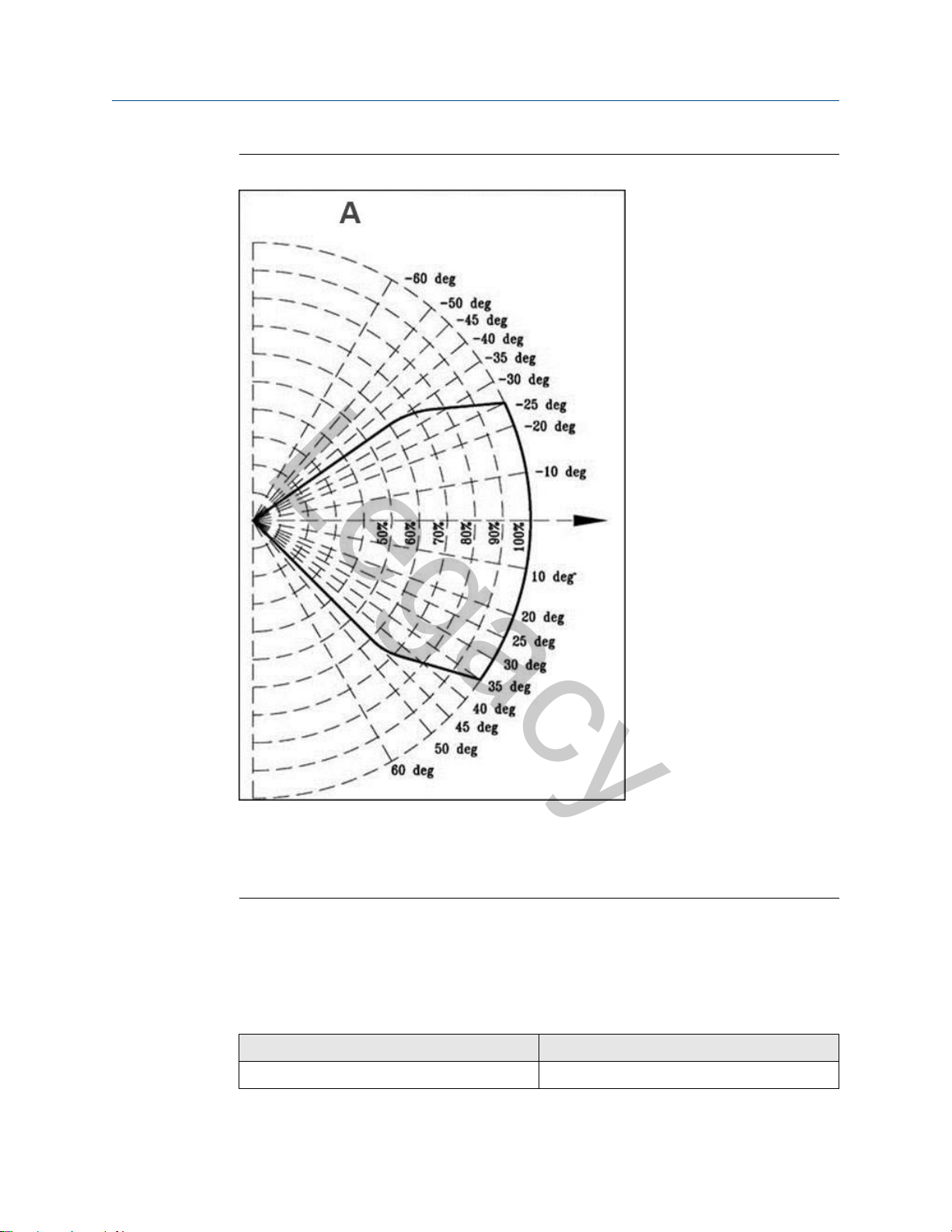
Figure 1-2: Vertical Field of View for Rosemount 975MR
A. Relative range
1.5.3 False alarms prevention
18 Emerson.com/Rosemount
• +50 ° (down)
• -45 ° (up)
To prevent false alarms, the detector will not alarm or react to the radiation sources
specified in the table below.
Table 1-3: Immunity to False Alarm Sources
Radiation source Immunity distance ft. (m)
Indirect or reflected sunlight IAD

Reference Manual Introduction
Legacy
00809-0100-4975 November 2021
Table 1-3: Immunity to False Alarm Sources (continued)
Radiation source Immunity distance ft. (m)
Vehicle headlights (low beam) conforming to
MS53023-1
Incandescent frosted glass light, 300 W IAD
Fluorescent light with white enamel reflector,
standard office or shop, 70 W (or two 35 W)
Electric arc (15/32 in. [12 mm] gap at 4,000 Vac,
60 Hz)
Arc welding (5/16 in. [6 mm] rod; 210 A) See Table 1-4
Ambient light extremes (darkness to bright light
with snow, water, rain, desert glare, and fog)
Bright colored clothing, including red and safety
orange
Electronic flash (180 W-seconds minimum
output)
Movie light, 625 W quartz DWY lamp (Sylvania
S.G. - 55 or equivalent)
Blue-green dome light conforming to
M251073-1
Flashlight (MX 99 I/U) IAD
Radiation heater, 3,000 W > 3 (1)
IAD
IAD
IAD
IAD
IAD
IAD
> 6.5 (2)
IAD
Radiation heater, 1,000 W with fan IAD
Quartz lamp (1,000 W) > 3 (1)
Mercury vapor lamp IAD
Grinding metal IAD
Lit cigar > 1 (0.3)
Lit cigarette > 1 (0.3)
Match, wood, stick, including flare up > 13 (4)
1. IAD: Immune at any distance.
2. All sources are chopped from 0 to 20 Hz.
Table 1-4: Welding Immunity Distance
Sensitivity setting Detection range Immunity distance
1 50 ft. (15 m) > 6 ft. (2 m)
2 100 ft. (30 m) > 12 ft. (4 m)
3 150 ft. (45 m) > 17 ft. (6 m)
4 215 ft. (65 m) >25 ft. (7.5 m)
Rosemount 975MR 19
Introduction Reference Manual
Legacy
November 2021 00809-0100-4975
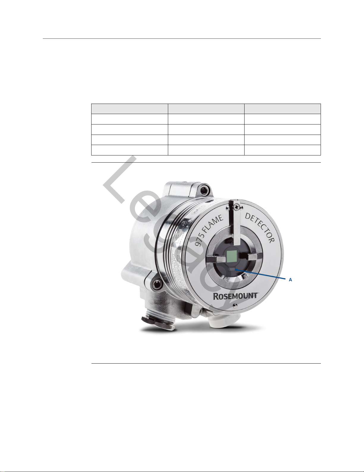
1.5.4 Visual indicators
One three-color LED indicator is located inside the detector window, as shown in Figure
1-3. The detector statuses are listed in Table 1-5.
Table 1-5: LED Indications
Detector status LED color LED mode
Fault, BIT Fault Yellow 4 Hz - flashing
Normal Green 1 Hz - flashing
Warning Red 2 Hz -flashing
Alarm Red Steady
Figure 1-3: Indication LED
A. Indicator LED
1.5.5 Output signals
Outputs are available according to the default configuration or the wiring options selected
for the detector.
Determine the outputs of your model according to Table 1-6.
The detector incorporates several types of output suitable to different control systems.
20 Emerson.com/Rosemount

Reference Manual Introduction
Legacy
00809-0100-4975 November 2021
• 0-20 mA (stepped) with HART
• Relays (alarm, fault, auxiliary)
• RS-485 Modbus
Table 1-6: Available Output Types
Output type Version Detector status
Alarm relay 975MR- output configurations
Auxiliary relay 975MR - output configurations
Fault relay 975MR - output configurations
0-20 mA current output 975MR - output configuration
®
®
1AXXXXX, 1RXXXXX, and
2RXXXXX
975MR - output configurations
2AXXXXX and 3AXXXXX
1AXXXXX, 2AXXXXX, and
1RXXXXX
1AXXXXX, 2AXXXXX, and
1RXXXXX
975MR - output configurations
3AXXXXX and 2RXXXXX
1AXXXXX
The relay is N.O.
The relay is N.O. and N.C.
The relay is N.O.
The relay is N.C. energized.
The relay is N.O. energized.
Sink with the HART protocol
(can be changed to Source - see
Figure B-3, Figure B-4, and
Figure B-5).
975MR - output configurations
2AXXXXX and 3AXXXXX
RS-485 All versions Modbus protocol
1.5.6 Detector status
The possible detector function statuses are listed in the table below. Use HART® or
Modbus® to see a more detailed fault analysis.
Table 1-7: Detector Statuses
Status Description
Normal Normal operation.
BIT Built-in test being performed.
Warning Fire detected - changed to Warning (pre-alarm state).
Alarm Fire detected - changed to Fire Alarm state.
Latched alarm (optional) The alarm outputs remain latched on following detection of a fire
that has already been extinguished.
BIT fault A fault is detected during built-in test sequence or other electric
failure. The detector will continue to detect for fire.
Source with the HART protocol
Rosemount 975MR 21

Introduction Reference Manual
Legacy
November 2021
Table 1-7: Detector Statuses (continued)
Status Description
Fault A fault is detected when the power supply is too low or due to a
software fault or electrical failure. The detector will not detect fire
in this condition.
In each state, the detector activates different outputs, as specified in Table 1-8.
Table 1-8: Output Signals vs. Detector State
Detector state LED indicator LED mode Alarm relay Auxiliary relay Fault relay mA output
Normal Green 1 Hz Off Off On 4 mA
On
(1)
(1)
(1)
On 16 mA
On 20 mA
Off 16 mA
Warning Red 2 Hz Off On
(2)
Alarm
(3)
Latch
BIT Fault
Warning at BIT
Fault
(4)
Red Constant On On On 20 mA
Red Constant On Off On 20 mA
Yellow 4 Hz Off Off Off 2 mA
Red 2 Hz Off On
00809-0100-4975
Alarm at BIT
Fault
Fault Yellow 4 Hz Off Off Off 0 mA
(1) The auxiliary relay can be activated at the Warning level or Alarm level, depending on programmed function.
(2) The alarm outputs are activated while alarm conditions exist and will stop approximately five seconds after a fire is no
longer detected.
(3) The Alarm state can be optionally latched via programmed function. (Default is non-latching).
(4) The detector will remain in BIT Fault state until it has passed a successful built-in test.
Red Constant On On Off 20 mA
Note
The outputs depend on the output configurations.
Optional latching
Alarms are set as non-latching by default. However, the detector includes a latched alarm
output capability, which operates according to the programmed function.
If selected, upon detection of a fire, the detection signal is latched until the operator
manually resets the detector (disconnecting the power supply or performing a manual
built-in test [see Manual built-in test]).
Latching affects the alarm relay, 0-20 mA output, and the alarm LED. The auxiliary relay is
latched only when the programmable function Auxiliary Relay is set to Yes.
22 Emerson.com/Rosemount

Reference Manual Introduction
Legacy
00809-0100-4975 November 2021
NOTICE
The auxiliary relay is available only in models with output configurations - 1RXXXXX and
2RXXXXX.
The 0-20 mA is available only in models with output configurations - 1AXXXXX, 2AXXXXX,
and 3AXXXXX.
1.6 Internal detector tests
The detector performs two types of self-tests:
• Continuous feature test
• Built-in test (BIT)
1.6.1 Continuous feature test
The detector is supplied with default settings, including a continuous feature test.
During normal operation, the detector tests itself continuously and indicates a fault if a
failure is found.
The detector continuously tests:
• Input voltage level
• All internal regulator voltage level
• Voltage level status of sensor and sensor circuitry for noise or disconnection in the
electronic circuitry
• 0-20 mA level output
• Relays and heater operation
• Processor watch dog
• Software
• Memory
• Oscillator frequency
Response to a fault indication
If a failure is found, the detector indicates it by:
• Fault relay:
— Opens in output configurations 1A, 2A, and 1R
— Closes in output configurations 3A and 2R
• 0-20 mA: indicates fault (0 mA or 2 mA) in output configurations 1A, 2A, and 3A
• LED - yellow flashes (4 Hz)
• Correcting the fault
Rosemount 975MR 23

Introduction Reference Manual
Legacy
November 2021 00809-0100-4975
The fault indications remain until the detector's power is removed. The fault indications
return if the fault is still found when power is restored.
1.6.2 Built-in test (BIT)
The detector's built-in test (BIT) also checks the following:
• Electronics circuitry
• Sensors
• Window cleanliness
The detector can be set to perform the built-in test in the following modes:
• Automatically and manually
• Manually only
NOTICE
In a manual built-in test, the outputs may also be tested; apply control system inhibit if
this could initiate other systems.
How the built-in test operates
• The detector's status remains unchanged if the result of a built-in test is the same as
the current status (Normal or BIT Fault).
• The detector's status is changed (from Normal to BIT Fault or vice versa) if the built-in
test differs from the current status.
NOTICE
In BIT Fault status, the detector can continue to detect a fire.
Automatic built-in test
The detector automatically performs a built-in test every fifteen minutes. A successful
built-in test sequence does not activate any indicator.
All outputs of built-in test results function as described in Table 1-9 and Table 1-10, and
the built-in test is automatically executed every one minute.
This continues until a successful built-in test occurs, when the detector resumes normal
operation.
Table 1-9: Results of a Successful Built-in Test
Output Result
Fault relay • Output configurations 1A, 2A, and 1R:
remain CLOSED
• Output configurations 3A and 2R: remain
OPEN
24 Emerson.com/Rosemount
Loading...